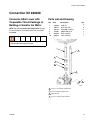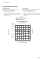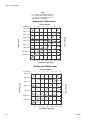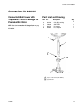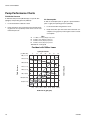
1
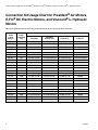
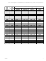
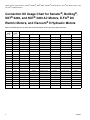
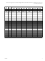
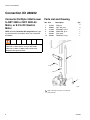
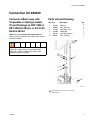
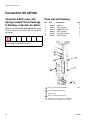
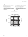
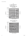
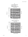
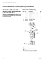
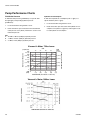
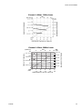
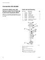
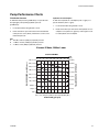
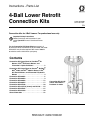
Instructions - Parts List
4-Ball Lower Retrofit
Connection Kits
311876F
EN
Connection kits for 4-Ball Lowers. For professional use only.
Important Safety Instructions
Read all warnings and instructions in your
pump Operation manual. Save these instructions.
See the Connection Kit Usage Charts on pages 2-5
to select the correct connection kit for your lower and motor.
A Shield Kit may also be required. See manual 406876
to order the correct shield kit for your pump.
Contents
Connection Kit Usage Chart for President® Air
Motors, E-Flo® DC Electric Motors, and
Viscount® I+ Hydraulic Motors . . . . . . . . . . . . 2
Connection Kit Usage Chart for Senator®, Bulldog®,
NXT® 2200, and NXT® 3400 Air Motors, E-Flo®
DC Electric Motors, and Viscount® II Hydraulic
Motors . . . . . . . . . . . . . . . . . . . . . . . . . . . . . . . . 4
Connection Kit 288202 . . . . . . . . . . . . . . . . . . . . . . 6
Connection Kit 288209 . . . . . . . . . . . . . . . . . . . . . . 9
Connection Kit 288208 . . . . . . . . . . . . . . . . . . . . . 13
Connection Kit 288504 . . . . . . . . . . . . . . . . . . . . . 17
Connection Kit 24F308 . . . . . . . . . . . . . . . . . . . . . 20
Connection Kits 24J185 (shown) and 24J186 . . . 24
Connection Kit 24F065 . . . . . . . . . . . . . . . . . . . . . 27
Connection Kit 24J390 . . . . . . . . . . . . . . . . . . . . . 30
Graco Information . . . . . . . . . . . . . . . . . . . . . . . . . 32
Connection Kit 24J185
shown mounted on a
President air motor
TI16810a
Connection Kit Usage Chart for President® Air Motors, E-Flo® DC Electric Motors, and Viscount® I+ Hydraulic Motors
Connection Kit Usage Chart for President® Air Motors,
E-Flo® DC Electric Motors, and Viscount® I+ Hydraulic
Motors
Refer to the following chart to select the correct Connection Kit for your pump lower and motor.
*
2
Connection Kit Part No. (see page numbers)
Pump
Lower
Part No.
Pump
Lower Size
(cc)
President
President
(stubby size)
Viscount I+
E-Flo DC
24F413
750
24J185 (24-26)
24J186 (24-26)
24F065 (27-29)
288209
24F414
750
24J185 (24-26)
24J186 (24-26)
24F065 (27-29)
288209
24F415
750
24J185 (24-26)
24J186 (24-26)
24F065 (27-29)
288209
24F416
750
24J185 (24-26)
24J186 (24-26)
24F065 (27-29)
288209
24F420
750
24J185 (24-26)
24J186 (24-26)
24F065 (27-29)
288209
24F421*
750
24J185 (24-26)
not recommended
not recommended
not recommended
24F422*
750
24J185 (24-26)
not recommended
not recommended
not recommended
24F423*
750
24J185 (24-26)
not recommended
not recommended
not recommended
24F424
1000
24J185 (24-26)
24J186 (24-26)
24F065 (27-29)
288209
24F425
1000
24J185 (24-26)
24J186 (24-26)
24F065 (27-29)
288209
24F426
1000
24J185 (24-26)
24J186 (24-26)
24F065 (27-29)
288209
24F427
1000
24J185 (24-26)
24J186 (24-26)
24F065 (27-29)
288209
24F431
1000
24J185 (24-26)
24J186 (24-26)
24F065 (27-29)
288209
24F432
1500
24J185 (24-26)
24J186 (24-26)
24F065 (27-29)
288209
24F433
1500
24J185 (24-26)
24J186 (24-26)
24F065 (27-29)
288209
24F434
1500
24J185 (24-26)
24J186 (24-26)
24F065 (27-29)
288209
24F435
1500
24J185 (24-26)
24J186 (24-26)
24F065 (27-29)
288209
24F439
1500
24J185 (24-26)
24J186 (24-26)
24F065 (27-29)
288209
24F440
2000
not recommended
not recommended
24F065 (27-29)
288209
24F441
2000
not recommended
not recommended
24F065 (27-29)
288209
24F442
2000
not recommended
not recommended
24F065 (27-29)
288209
24F443
2000
not recommended
not recommended
24F065 (27-29)
288209
24F447
2000
not recommended
not recommended
24F065 (27-29)
288209
Drum mounted pump lower with open wet-cup and spring loaded packings.
311876F
Connection Kit Usage Chart for President® Air Motors, E-Flo® DC Electric Motors, and Viscount® I+ Hydraulic Motors
Connection Kit Part No. (see page numbers)
Pump
Lower
Part No.
Pump
Lower Size
(cc)
President
President
(stubby size)
Viscount I+
E-Flo DC
253033
1000
288504 (17-19)
24J186 (24-26)
24F065 (27-29)
288209
253034
1500
288504 (17-19)
24J186 (24-26)
24F065 (27-29)
288209
253035
2000
288504 (17-19)
24J186 (24-26)
24F065 (27-29)
288209
253061
1000
288504 (17-19)
24J186 (24-26)
24F065 (27-29)
288209
253062
1500
288504 (17-19)
24J186 (24-26)
24F065 (27-29)
288209
253063
2000
288504 (17-19)
24J186 (24-26)
24F065 (27-29)
288209
253085
1500
288504 (17-19)
24J186 (24-26)
24F065 (27-29)
288209
253086
2000
288504 (17-19)
24J186 (24-26)
24F065 (27-29)
288209
253396
2000
288504 (17-19)
24J186 (24-26)
24F065 (27-29)
288209
253397
1500
288504 (17-19)
24J186 (24-26)
24F065 (27-29)
288209
253398
1000
288504 (17-19)
24J186 (24-26)
24F065 (27-29)
288209
253423
1000
288504 (17-19)
24J186 (24-26)
24F065 (27-29)
288209
253520
1000
288504 (17-19)
24J186 (24-26)
24F065 (27-29)
288209
253521
1500
288504 (17-19)
24J186 (24-26)
24F065 (27-29)
288209
253522
2000
288504 (17-19)
24J186 (24-26)
24F065 (27-29)
288209
253523
1000
288504 (17-19)
24J186 (24-26)
24F065 (27-29)
288209
253524
1500
288504 (17-19)
24J186 (24-26)
24F065 (27-29)
288209
253525
2000
288504 (17-19)
24J186 (24-26)
24F065 (27-29)
288209
253568
1000
288504 (17-19)
24J186 (24-26)
24F065 (27-29)
288209
253569
1500
288504 (17-19)
24J186 (24-26)
24F065 (27-29)
288209
253570
2000
288504 (17-19)
24J186 (24-26)
24F065 (27-29)
288209
24E664†
1000
24J185 (24-26)
24J186 (24-26)
24F065 (27-29)
288209
24F062†
1000
24J185 (24-26)
24J186 (24-26)
24F065 (27-29)
288209
24H346†
1500
24J185 (24-26)
24J186 (24-26)
24F065 (27-29)
288209
24H347†
1500
24J185 (24-26)
24J186 (24-26)
24F065 (27-29)
288209
24H348†
2000
24J185 (24-26)
24J186 (24-26)
24F065 (27-29)
288209
24H349†
2000
24J185 (24-26)
24J186 (24-26)
24F065 (27-29)
288209
† Retrofitted lowers.
311876F
3
Connection Kit Usage Chart for Senator®, Bulldog®, NXT® 2200, and NXT® 3400 Air Motors, E-Flo® DC Electric Motors, and
Viscount® II Hydraulic Motors
Connection Kit Usage Chart for Senator®, Bulldog®,
NXT® 2200, and NXT® 3400 Air Motors, E-Flo® DC
Electric Motors, and Viscount® II Hydraulic Motors
Refer to the following chart to select the correct Connection Kit for your pump lower and motor.
4
Connection Kit Part No. (see page numbers)
Pump
Lower
Part No.
Pump
Lower
Size (cc)
Senator
NXT 2200
Bulldog
NXT 3400
Viscount II
E-Flo DC
15D787
1500
not applicable
288202 (6-8)
not applicable
288202 (6-8)
not recommended
288202 (6-8)
239834
1000
not applicable
288202 (6-8)
not applicable
not recommended
not recommended
288202 (6-8)
239835
1500
not applicable
288202 (6-8)
not applicable
288202 (6-8)
not recommended
288202 (6-8)
239837
1000
not applicable
288202 (6-8)
not applicable
not recommended
not recommended
288202 (6-8)
239838
1500
not applicable
288202 (6-8)
not applicable
288202 (6-8)
not recommended
288202 (6-8)
24F424
1000
24F308 (20-23)
288209
not recommended
not recommended
not recommended
288209
24F425
1000
24F308 (20-23)
288209
not recommended not recommended
not recommended
288209
24F426
1000
24F308 (20-23)
288209
not recommended
not recommended
not recommended
288209
24F427
1000
24F308 (20-23)
288209
not recommended not recommended
not recommended
288209
24F431
1000
24F308 (20-23)
288209
not recommended
not recommended
not recommended
288209
24F432
1500
24F308 (20-23)
288209
24F308 (20-23)
not recommended
not recommended
288209
24F433
1500
24F308 (20-23)
288209
24F308 (20-23)
not recommended
not recommended
288209
24F434
1500
24F308 (20-23)
288209
24F308 (20-23)
not recommended
not recommended
288209
24F435
1500
24F308 (20-23)
288209
24F308 (20-23)
not recommended
not recommended
288209
24F439
1500
24F308 (20-23)
288209
24F308 (20-23)
not recommended
not recommended
288209
24F440
2000
24F308 (20-23)
288209
24F308 (20-23)
288209
24J390 (30-31)
288209
24F441
2000
24F308 (20-23)
288209
24F308 (20-23)
288209
24J390 (30-31)
288209
24F442
2000
24F308 (20-23)
288209
24F308 (20-23)
288209
24J390 (30-31)
288209
24F443
2000
24F308 (20-23)
288209
24F308 (20-23)
288209
24J390 (30-31)
288209
24F447
2000
24F308 (20-23)
288209
24F308 (20-23)
288209
24J390 (30-31)
288209
240606
1500
not applicable
288202 (6-8)
not applicable
288202 (6-8)
not recommended
288202 (6-8)
240607
1500
not applicable
288202 (6-8)
not applicable
288202 (6-8)
not recommended
288202 (6-8)
240608
1000
not applicable
288202 (6-8)
not applicable
not recommended
not recommended
288202 (6-8)
240609
1000
not applicable
288202 (6-8)
not applicable
not recommended
not recommended
288202 (6-8)
311876F
Connection Kit Usage Chart for Senator®, Bulldog®, NXT® 2200, and NXT® 3400 Air Motors, E-Flo® DC Electric Motors, and
Viscount® II Hydraulic Motors
Connection Kit Part No. (see page numbers)
Pump
Lower
Part No.
Pump
Lower
Size (cc)
Senator
NXT 2200
253033
1000
288208 (17-19)
288209
Bulldog
NXT 3400
not recommended not recommended
Viscount II
E-Flo DC
not recommended
288209
253034
1500
288208 (17-19)
288209
288208 (17-19)
288209
not recommended
288209
253035
2000
288208 (17-19)
288209
288208 (17-19)
288209
not recommended
288209
253061
1000
288208 (17-19)
288209
not recommended
not recommended
not recommended
288209
253062
1500
288208 (17-19)
288209
288208 (17-19)
288209
not recommended
288209
253063
2000
288208 (17-19)
288209
288208 (17-19)
288209
not recommended
288209
253085
1500
288208 (17-19)
288209
288208 (17-19)
288209
not recommended
288209
253086
2000
288208 (17-19)
288209
288208 (17-19)
288209
not recommended
288209
253396
2000
288208 (17-19)
288209
288208 (17-19)
288209
not recommended
288209
288208 (17-19)
288209
253397
1500
288208 (17-19)
288209
253398
1000
288208 (17-19)
288209
not recommended not recommended
not recommended
288209
not recommended
288209
253423
1000
288208 (17-19)
288209
not recommended
not recommended
not recommended
288209
253520
1000
288208 (17-19)
288209
not recommended not recommended
not recommended
288209
253521
1500
288208 (17-19)
288209
288208 (17-19)
288209
not recommended
288209
253522
2000
288208 (17-19)
288209
288208 (17-19)
288209
not recommended
288209
253523
1000
288208 (17-19)
288209
not recommended
not recommended
not recommended
288209
253524
1500
288208 (17-19)
288209
288208 (17-19)
288209
not recommended
288209
288208 (17-19)
288209
253525
2000
288208 (17-19)
288209
253568
1000
288208 (17-19)
288209
not recommended not recommended
253569
1500
288208 (17-19)
288209
24E664†
1000
24F308 (20-23)
288209
not recommended not recommended
288208 (17-19)
288209
not recommended
288209
not recommended
288209
not recommended
288209
not recommended
288209
24F062†
1000
24F308 (20-23)
288209
not recommended
not recommended
not recommended
288209
24H346†
1500
24F308 (20-23)
288209
24F308 (20-23)
288209
not recommended
288209
24H347†
1500
24F308 (20-23)
288209
24F308 (20-23)
288209
not recommended
288209
24H348†
2000
24F308 (20-23)
288209
24F308 (20-23)
288209
24J390 (30-31)
288209
24H349†
2000
24F308 (20-23)
288209
24F308 (20-23)
288209
24J390 (30-31)
288209
†
Retrofitted lowers.
311876F
5
Connection Kit 288202
Connection Kit 288202
Connects Old Style 4-Ball Lower
to NXT 2200 or NXT 3400 Air
Motor, or E-Flo DC Electric
Motor
NOTE: See the Connection Kit Usage Chart on page
4 to find the lowers and motors which use Connection
Kit 288202.
Parts List and Drawing
Ref. Part.
1
2
3
5
7
14
Description
15G924
108683
111368
15H980
100103
108284
Qty
3
3
1
1
1
1
ROD, tie
NUT, lock, hex
SEALANT; 0.5 cc
ADAPTER, lg mr
PIN, cotter
PACKING, o-ring
Using an NXT 2200 motor or an E-Flo DC 2 HP
motor with a 750cc lower or using an NXT 3400
motor with a 750cc or 1000cc lower could cause
dangerous overpressurization.
1
5
1
7
14
2
TI8984a
1
6
Apply sealant (3) and torque to 145-155 ft-lb
(196 -210 N•m)
311876F
Connection Kit 288202
Pump Performance Charts
NOTE: See pages 10-12 for E-Flo DC Performance
Charts.
Air Consumption
To find air consumption (l/min. or gpm) at a specific fluid flow
(l/min. or gpm) and operating pressure (A/B/C):
Fluid Outlet Pressure
To find fluid outlet pressure (MPa/bar/psi) at a specific flow
(lpm/gpm) and operating pressure (A/B/C):
1.
Locate desired flow at bottom of chart.
2.
Follow vertical line up to intersection with selected operating pressure curve (solid line). Follow left to scale to read
fluid outlet pressure.
1.
Locate desired flow along bottom of chart.
2.
Read vertical line up to intersection with selected air consumption curve (gray line). Follow right to scale to read air
consumption.
Key
A
0.7 MPa, 7 bar (100 psi) air pressure
B
0.5 MPa, 4.9 bar (70 psi) air pressure
C
0.3 MPa, 2.8 bar (40 psi) air pressure
Test Fluid: No. 10 Weight Oil
NXT 2200 with 1000cc Lower
cycles per minute
7
psi (MPa, bar)
450 (3.1, 31)
400 (2.7, 27)
14
21
28
35
42
49
70
A
A
60
B
300 (2.0, 20)
B
40
250 (1.7, 17)
200 (1.3, 13)
150 (1.0, 10)
50
C
30
C
Air Flow (scfm)
Fluid Pressure
350 (2.4, 24)
20
100 (0.68, 6.8)
10
50 (0.34, 3.4)
0
2.0
(7.5)
6.0
8.0
4.0
(15.1) (22.7) (30.2)
12.0
10.0
(37.8) (45.4)
14.0
(53.0)
Fluid Flow in gpm (lpm)
311876F
7
Connection Kit 288202
Key
A
0.7 MPa, 7 bar (100 psi) air pressure
B
0.5 MPa, 4.9 bar (70 psi) air pressure
C
0.3 MPa, 2.8 bar (40 psi) air pressure
Test Fluid: No. 10 Weight Oil
NXT 2200 with 1500cc Lower
cycles per minute
psi (MPa, bar)
5
10
15
21
26
31
36
300 (2.0, 20)
50
A
A
45
40
35
B
200 (1.3, 13)
B
30
25
150 (1.0, 10)
20
C
100 (0.68, 6.8)
Air Flow (scfm)
Fluid Pressure
250 (1.7, 17)
15
C
10
50 (0.34, 3.4)
5
0
2.0
(7.5)
12.0
6.0
8.0
10.0
4.0
(15.1) (22.7) (30.2) (37.8) (45.4)
14.0
(53.0)
Fluid Flow in gpm (lpm)
NXT 3400 with 1500cc Lower
cycles per minute
psi (MPa, bar)
5
10
15
21
26
31
36
500 (3.8, 38
450 (3.4, 34)
80
A
A
70
400 (3.1, 31)
60
B
B
300 (2.4, 24)
250 (2.0, 20)
200 (1.7, 17)
50
40
C
30
C
Air Flow (scfm)
Fluid Pressure
350 (2.7, 27)
150 (1.3, 13)
20
100 (0.68, 6.8)
10
50 (0.34, 3.4)
0
2.0
(7.5)
12.0
6.0
8.0
10.0
4.0
(15.1) (22.7) (30.2) (37.8) (45.4)
14.0
(53.0)
Fluid Flow in gpm (lpm)
8
311876F
Connection Kit 288209
Connection Kit 288209
Connects 4-Ball Lower with
Torqueable or Spring Loaded
Throat Packings to NXT 2200 or
NXT 3400 Air Motor, or E-Flo DC
Electric Motor
NOTE: See the Connection Kit Usage Charts on
pages 2-5 to find the lowers and motors which use Connection Kit 288209.
Parts List and Drawing
Ref. Part.
1
2
3
5
7
8
Description
15G924
108683
111368
15H369
184128
184059
Qty
3
3
1
1
2
1
ROD, tie
NUT, lock, hex
SEALANT; 0.5 cc
ADAPTER
COLLAR, coupling
NUT, coupling
Using an NXT 2200 motor or an E-Flo DC 2 HP
motor with a 750cc lower or using an NXT 3400
motor with a 750cc or 1000cc lower could cause
dangerous overpressurization.
1
5
1
7
8
2
TI21556a
1
311876F
Apply sealant (3) and torque to 145-155 ft-lb
(196 -210 N•m)
9
Connection Kit 288209
Pump Performance Charts
NOTE: See pages 7-8 for NXT 2200 and NXT 3400 Performance Charts.
Fluid Outlet Pressure
To find fluid outlet pressure (psi/MPa/bar) at a specific flow
(gpm/lpm) and percentage of maximum force (A/B/C):
1.
Locate desired flow at bottom of chart.
2.
Follow vertical line up to intersection with selected percentage of maximum force (see the Key below).
3.
Follow left to vertical scale to read fluid outlet pressure.
Key to E-Flo DC Performance Charts
NOTE: The charts show the motor operating at 100%, 70%,
and 40% of maximum force. These values are approximately
equivalent to an air motor operating at 100, 70, and 40 psi..
A
100% of maximum force
B
70% of maximum force
C
40% of maximum force
Test Fluid: No. 10 Weight Oil
1 HP Motor (1400 lb maximum force) with 750cc Lower
cycles per minute
psi (MPa, bar)
Fluid Pressure
A
B
C
Fluid Flow in gpm (lpm)
10
311876F
Connection Kit 288209
1 HP Motor (1400 lb maximum force) with 1000cc Lower
cycles per minute
Fluid Pressure
psi (MPa, bar)
A
B
C
Fluid Flow in gpm (lpm)
2 HP Motor (2800 lb maximum force) with 1000cc Lower
cycles per minute
psi (MPa, bar)
Fluid Pressure
A
B
C
Fluid Flow in gpm (lpm)
311876F
11
Connection Kit 288209
2 HP Motor (2800 lb maximum force) with 1500cc Lower
cycles per minute
psi (MPa, bar)
Fluid Pressure
A
B
C
Fluid Flow in gpm (lpm)
2 HP Motor (2800 lb maximum force) with 2000cc Lower
cycles per minute
Fluid Pressure
psi (MPa, bar)
A
B
C
Fluid Flow in gpm (lpm)
12
311876F
Connection Kit 288208
Connection Kit 288208
Connects 4-Ball Lower with
Torqueable Throat Packings to
Bulldog or Senator Air Motor
NOTE: See the Connection Kit Usage Chart on page
5 to find the lowers and motors which use Connection
Kit 288208.
Parts List and Drawing
Ref.
1
2
3
5
8
10
Part.
Description
183089
108527
184128
15H981
184059
183079
Qty
3
3
2
1
1
1
ROD, tie
NUT, lock, hex
COLLAR, coupling
ADAPTER, lg mr
NUT, coupling
NUT, coupling
Using a Bulldog air motor with a 1000cc lower could
cause dangerous overpressurization.
5
1
2
10
4
3
1
3
8
3
2
2
TI8985a
311876F
1
Torque to 145-150 ft-lb (196-203 N•m).
2
Torque to 50-60 ft-lb (68-91 N•m).
3
Apply lubricant.
4
Torque to 75-80 ft-lb (102-109 N•m).
13
Connection Kit 288208
Pump Performance Charts
Fluid Outlet Pressure
Air Consumption
To find fluid outlet pressure (MPa/bar/psi) at a specific flow
(lpm/gpm) and operating pressure (A/B/C):
To find air consumption (l/min. or gpm) at a specific fluid flow
(l/min. or gpm) and operating pressure (A/B/C):
1.
Locate desired flow at bottom of chart.
1.
Locate desired flow along bottom of chart.
2.
Follow vertical line up to intersection with selected operating pressure curve (solid line). Follow left to scale to read
fluid outlet pressure.
2.
Read vertical line up to intersection with selected air consumption curve (gray line). Follow right to scale to read air
consumption.
Key
A 0.7 MPa, 7 bar (100 psi) air pressure
B 0.5 MPa, 4.9 bar (70 psi) air pressure
C 0.3 MPa, 2.8 bar (40 psi) air pressure
Test Fluid: No. 10 Weight Oil
Senator with 1000cc Lower
cycles per minute
psi (MPa, bar)
350 (2.4, 24)
7
14
21
28
35
42
49
60
A
A
300 (2.0, 20)
50
Fluid Pressure
B
200 (1.3, 13)
40
B
30
C
150 (1.0, 10
100 (0.69, 6.9)
Air Flow (scfm)
250 (1.7, 17)
20
C
10
50 (0.34, 3.4)
0
2.0
(7.5)
12.0
6.0
8.0
10.0
4.0
(15.1) (22.7) (30.2) (37.8) (45.4)
14.0
(53.0)
Fluid Flow in gpm (lpm)
14
311876F
Connection Kit 288208
Key
A
0.7 MPa, 7 bar (100 psi) air pressure
B
0.5 MPa, 4.9 bar (70 psi) air pressure
C
0.3 MPa, 2.8 bar (40 psi) air pressure
Test Fluid: No. 10 Weight Oil
Senator with 1500cc Lower
cycles per minute
psi (MPa, bar)
300 (2.0, 20)
250 (1.7, 17)
5
10
15
21
26
31
36
45
A
A
40
35
Fluid Pressure
B
B
30
25
150 (1.0, 10
20
C
100 (0.69, 6.9)
C
Air Flow (scfm)
200 (1.3, 13)
15
10
50 (0.34, 3.4)
5
0
2.0
(7.5)
6.0
8.0
4.0
(15.1) (22.7) (30.2)
12.0
10.0
(37.8) (45.4)
14.0
(53.0)
Fluid Flow in gpm (lpm)
Senator with 2000cc Lower
cycles per minute
psi (MPa, bar)
4
7
11
15
19
200 (1.3, 13)
180 (1.2, 12)
23
A
A
25
160 (1.1, 11)
B
B
20
120 (0.82, 8.2)
15
100 (0.69, 6.9)
80 (0.55, 5.5)
C
C
60 (0.41, 4.1)
40 (0.27, 2.7)
Air Flow (scfm)
140 (0.9, 9.6
Fluid Pressure
26
30
10
5
20 (0.13, 1.3
0
2.0
(7.5)
6.0
8.0
4.0
(15.1) (22.7) (30.2)
12.0
10.0
(37.8) (45.4)
14.0
(53.0)
Fluid Flow in gpm (lpm)
311876F
15
Connection Kit 288208
Key
A
0.7 MPa, 7 bar (100 psi) air pressure
B
0.5 MPa, 4.9 bar (70 psi) air pressure
C
0.3 MPa, 2.8 bar (40 psi) air pressure
Test Fluid: No. 10 Weight Oil
Bulldog with 1500cc Lower
cycles per minute
5
psi (MPa, bar)
10
15
21
26
31
36
70
450 (3.1, 31)
A
400 (2.7, 27)
A
60
350 (2.4, 24)
Fluid Pressure
B
B
40
250 (1.7, 17)
200 (1.3, 13)
C
C
150 (1.0, 10
30
Air Flow (scfm)
50
300 (2.0, 20)
20
100 (0.69, 6.9)
10
50 (0.34, 3.4)
0
2.0
(7.5)
12.0
6.0
8.0
10.0
4.0
(15.1) (22.7) (30.2) (37.8) (45.4)
14.0
(53.0)
Fluid Flow in gpm (lpm)
Bulldog with 2000cc Lower
cycles per minute
4
psi (MPa, bar)
350 (2.4, 24)
300 (2.0, 20)
7
11
15
19
23
26
50
A
A
45
40
B
200 (1.3, 13)
B
35
30
25
150 (1.0, 10
C
C
20
Air Flow (scfm)
Fluid Pressure
250 (1.7, 17)
15
100 (0.69, 6.9)
10
50 (0.34, 3.4)
5
0
2.0
(7.5)
6.0
8.0
4.0
(15.1) (22.7) (30.2)
12.0
10.0
(37.8) (45.4)
14.0
(53.0)
Fluid Flow in gpm (lpm)
16
311876F
Connection Kit 288504
Connection Kit 288504
Connects 4-Ball Lower with
Torqueable Throat Packings to
President Air Motor
NOTE: See the Connection Kit Usage Chart on page
3 to find the lowers and motors which use Connection
Kit 288504.
Parts List and Drawing
Ref. Part.
3
5
7
8
184128
15J948
100579
184059
Description
Qty
2
1
1
1
COLLAR, coupling
ADAPTER
PIN, cotter
NUT, coupling
7
5
2
3
8
1
TI8986a
311876F
1
Torque to 145-150 ft-lb (197-203 N•m).
2
Apply lubricant.
17
Connection Kit 288504
Pump Performance Charts
Fluid Outlet Pressure
To find fluid outlet pressure (MPa/bar/psi) at a specific flow
(lpm/gpm) and operating pressure (A/B/C/D):
Air Consumption
To find air consumption (l/min. or gpm) at a specific fluid flow
(l/min. or gpm) and operating pressure (A/B/C/D):
1.
Locate desired flow at bottom of chart.
2.
Follow vertical line up to intersection with selected operating pressure curve (solid line). Follow left to scale to read
fluid outlet pressure.
1.
Locate desired flow along bottom of chart.
2.
Read vertical line up to intersection with selected air consumption curve (gray line). Follow right to scale to read air
consumption.
Key
A
1.17 MPa, 11.7 bar (170 psi) air pressure
B
0.7 MPa, 7 bar (100 psi) air pressure
C
0.5 MPa, 4.9 bar (70 psi) air pressure
D
0.3 MPa, 2.8 bar (40 psi) air pressure
Test Fluid: No. 10 Weight Oil
President with 1000cc Lower
cycles per minute
psi (MPa, bar)
400 (2.7, 27)
350 (2.4, 24)
8
17
25
33
42
51
59
60
A
A
50
40
250 (1.7, 17)
200 (1.3, 13)
B
B
30
C
150 (1.0, 10)
C
20
100 (0.69, 6.9)
Air Flow (scfm)
Fluid Pressure
300 (2.0, 20)
D
D
10
50 (0.34, 3.4)
0
2.0
(7.5)
6.0
8.0
4.0
(15.1) (22.7) (30.2)
12.0
10.0
(37.8) (45.4)
14.0
(53.0)
Fluid Flow in gpm (lpm)
18
311876F
Connection Kit 288504
Key
A
1.17 MPa, 11.7 bar (170 psi) air pressure
B
0.7 MPa, 7 bar (100 psi) air pressure
C
0.5 MPa, 4.9 bar (70 psi) air pressure
D
0.3 MPa, 2.8 bar (40 psi) air pressure
Test Fluid: No. 10 Weight Oil
President with 1500cc Lower
cycles per minute
psi (MPa, bar)
300 (2.0, 20)
6
12
18
25
30
37
43
A
A
45
40
250 (1.7, 17)
35
Fluid Pressure
150 (1.0, 10)
B 25
B
20
100 (0.69, 6.9)
C
C
Air Flow (scfm)
30
200 (1.3, 13)
15
D
10
D
50 (0.34, 3.4)
5
0
2.0
(7.5)
6.0
8.0
4.0
(15.1) (22.7) (30.2)
12.0
10.0
(37.8) (45.4)
14.0
(53.0)
Fluid Flow in gpm (lpm)
President with 2000cc Lower
cycles per minute
psi (MPa, bar)
200 (1.37, 13.7)
4
9
13
18
22
27
A
31
35
A
180 (1.24, 12.4)
30
160 (1.1, 11.0)
25
B
120 (0.82, 8.2)
B
20
100 (0.68, 6.8)
80 (0.55, 5.5)
15
C
C
60 (0.41, 4.1)
40 (0.27, 2.7)
10
D
D
20 (0.13, 1.3)
0
Air Flow (scfm)
Fluid Pressure
140 (0.96, 9.6)
2.0
(7.5)
12.0
6.0
8.0
10.0
4.0
(15.1) (22.7) (30.2) (37.8) (45.4)
5
14.0
(53.0)
Fluid Flow in gpm (lpm)
311876F
19
Connection Kit 24F308
Connection Kit 24F308
Connects 4-Ball Lower with
Spring Loaded Throat Packings
to Bulldog or Senator Air Motor
NOTE: See the Connection Kit Usage Chart on pages
4-5 to find the lowers and motors which use Connection
Kit 24F308.
Parts List and Drawing
Ref.
1
2
3
4
5
6
Part.
Description
183089
108527
16F214
184059
184128
183079
Qty
3
3
1
1
2
1
ROD, tie
NUT, lock, hex
ADAPTER, lg mr
NUT, coupling
COLLAR, coupling
NUT, coupling
Using a Bulldog air motor with a 1000cc lower could
cause dangerous overpressurization.
3
4
6
3
5
1
4
1
2
3
5
2
2
20
1
Torque to 145-150 ft-lb (196-203 N•m).
2
Torque to 50-60 ft-lb (68-91 N•m).
3
Apply lubricant.
4
Torque to 75-80 ft-lb (102-109 N•m).
5
Shield Kit is not included. See manual 406876
to order the correct shield kit for your pump.
TI8985b
311876F
Connection Kit 24F308
Pump Performance Charts
Fluid Outlet Pressure
Air Consumption
To find fluid outlet pressure (MPa/bar/psi) at a specific flow
(lpm/gpm) and operating pressure (A/B/C):
To find air consumption (l/min. or gpm) at a specific fluid flow
(l/min. or gpm) and operating pressure (A/B/C):
1.
Locate desired flow at bottom of chart.
1.
Locate desired flow along bottom of chart.
2.
Follow vertical line up to intersection with selected operating pressure curve (solid line). Follow left to scale to read
fluid outlet pressure.
2.
Read vertical line up to intersection with selected air consumption curve (gray line). Follow right to scale to read air
consumption.
Key
A 0.7 MPa, 7 bar (100 psi) air pressure
B 0.5 MPa, 4.9 bar (70 psi) air pressure
C 0.3 MPa, 2.8 bar (40 psi) air pressure
Test Fluid: No. 10 Weight Oil
Senator with 1000cc Lower
cycles per minute
psi (MPa, bar)
350 (2.4, 24)
7
14
21
28
35
42
49
60
A
A
300 (2.0, 20)
50
Fluid Pressure
B
200 (1.3, 13)
40
B
30
C
150 (1.0, 10
100 (0.69, 6.9)
Air Flow (scfm)
250 (1.7, 17)
20
C
10
50 (0.34, 3.4)
0
2.0
(7.5)
12.0
6.0
8.0
10.0
4.0
(15.1) (22.7) (30.2) (37.8) (45.4)
14.0
(53.0)
Fluid Flow in gpm (lpm)
311876F
21
Connection Kit 24F308
Key
A
0.7 MPa, 7 bar (100 psi) air pressure
B
0.5 MPa, 4.9 bar (70 psi) air pressure
C
0.3 MPa, 2.8 bar (40 psi) air pressure
Test Fluid: No. 10 Weight Oil
Senator with 1500cc Lower
cycles per minute
psi (MPa, bar)
300 (2.0, 20)
250 (1.7, 17)
5
10
15
21
26
31
36
45
A
A
40
35
Fluid Pressure
B
B
30
25
150 (1.0, 10
20
C
100 (0.69, 6.9)
C
Air Flow (scfm)
200 (1.3, 13)
15
10
50 (0.34, 3.4)
5
0
2.0
(7.5)
6.0
8.0
4.0
(15.1) (22.7) (30.2)
12.0
10.0
(37.8) (45.4)
14.0
(53.0)
Fluid Flow in gpm (lpm)
Senator with 2000cc Lower
cycles per minute
psi (MPa, bar)
4
7
11
15
19
200 (1.3, 13)
180 (1.2, 12)
23
A
A
25
160 (1.1, 11)
B
B
20
120 (0.82, 8.2)
15
100 (0.69, 6.9)
80 (0.55, 5.5)
C
C
60 (0.41, 4.1)
40 (0.27, 2.7)
Air Flow (scfm)
140 (0.9, 9.6
Fluid Pressure
26
30
10
5
20 (0.13, 1.3
0
2.0
(7.5)
12.0
6.0
8.0
10.0
4.0
(15.1) (22.7) (30.2) (37.8) (45.4)
14.0
(53.0)
Fluid Flow in gpm (lpm)
22
311876F
Connection Kit 24F308
Key
A
0.7 MPa, 7 bar (100 psi) air pressure
B
0.5 MPa, 4.9 bar (70 psi) air pressure
C
0.3 MPa, 2.8 bar (40 psi) air pressure
Test Fluid: No. 10 Weight Oil
Bulldog with 1500cc Lower
cycles per minute
psi (MPa, bar)
5
10
15
21
26
31
36
70
450 (3.1, 31)
A
400 (2.7, 27)
A
60
350 (2.4, 24)
Fluid Pressure
B
B
40
250 (1.7, 17)
200 (1.3, 13)
C
C
150 (1.0, 10
30
Air Flow (scfm)
50
300 (2.0, 20)
20
100 (0.69, 6.9)
10
50 (0.34, 3.4)
0
2.0
(7.5)
12.0
6.0
8.0
10.0
4.0
(15.1) (22.7) (30.2) (37.8) (45.4)
14.0
(53.0)
Fluid Flow in gpm (lpm)
Bulldog with 2000cc Lower
cycles per minute
psi (MPa, bar)
350 (2.4, 24)
300 (2.0, 20)
4
7
11
15
19
23
26
50
A
A
45
40
B
200 (1.3, 13)
B
35
30
25
150 (1.0, 10
C
C
20
Air Flow (scfm)
Fluid Pressure
250 (1.7, 17)
15
100 (0.69, 6.9)
10
50 (0.34, 3.4)
5
0
2.0
(7.5)
6.0
8.0
4.0
(15.1) (22.7) (30.2)
12.0
10.0
(37.8) (45.4)
14.0
(53.0)
Fluid Flow in gpm (lpm)
311876F
23
Connection Kits 24J185 (shown) and 24J186
Connection Kits 24J185 (shown) and 24J186
Connects 4-Ball Lower with
Spring Loaded Throat Packings
to President Air Motor
NOTE: See the Connection Kit Usage Chart on pages
2-3 to find the lowers and motors which use Connection
Kits 24J185 and 24J186.
Parts List and Drawing
Ref. Part.
1
Description
16H544
16H375
15G924
16H434
108683
15T311
184128
100103
2
3
4
5
6
ADAPTER; Kit 24J185 only
ADAPTER; Kit 24J186 only
TIE ROD; Kit 24J185 only
TIE ROD; Kit 24J186 only
NUT, lock, hex
NUT, coupling
COLLAR, coupling
PIN, cotter
Qty
1
1
3
3
3
1
2
1
6
1
5
4
1
2
2
2
5
1
3
TI6809a
24
1
Torque to 145-150 ft-lb (197-203 N•m).
2
Apply lubricant.
5
Shield Kit is not included. See manual 406876
to order the correct shield kit for your pump.
311876F
Connection Kits 24J185 (shown) and 24J186
Pump Performance Charts
Fluid Outlet Pressure
Air Consumption
To find fluid outlet pressure (MPa/bar/psi) at a specific flow
(lpm/gpm) and operating pressure (A/B/C):
To find air consumption (l/min. or gpm) at a specific fluid flow
(l/min. or gpm) and operating pressure (A/B/C):
1.
Locate desired flow at bottom of chart.
1.
Locate desired flow along bottom of chart.
2.
Follow vertical line up to intersection with selected operating pressure curve (solid line). Follow left to scale to read
fluid outlet pressure.
2.
Read vertical line up to intersection with selected air consumption curve (dashed line). Follow left to scale to read
air consumption.
Key
A
0.7 MPa, 7 bar (100 psi) air pressure
B
0.5 MPa, 4.9 bar (70 psi) air pressure
C
0.3 MPa, 2.8 bar (40 psi) air pressure
Test Fluid: No. 10 Weight Oil
President with 750cc Lower
cycles per minute
500
(3.5, 35)
12
25
37
50
62
A
200
(1.3, 13)
B
100
(0.69, 6.9)
C
0
2.0
(7.5)
4.0
6.0
(15.1) (22.7)
8.0
10.0 12.0 14.0
(30.2) (37.8) (45.4) (53.0)
Fluid Flow in gpm (lpm)
311876F
(m3
/min)
50
(1.40)
Air Consumption
Fluid Pressure
400
(2.7, 27)
300
(2.0, 20)
cycles per minute
scfm
psi (MPa, bar)
12
25
37
40
(1.12)
50
62
A
30
(0.84)
B
20
(0.56)
C
10
(0.28)
0
2.0
(7.5)
4.0
6.0
(15.1) (22.7)
8.0
10.0 12.0 14.0
(30.2) (37.8) (45.4) (53.0)
Fluid Flow in gpm (lpm)
25
Connection Kits 24J185 (shown) and 24J186
Key
A
0.7 MPa, 7 bar (100 psi) air pressure
B
0.5 MPa, 4.9 bar (70 psi) air pressure
C
0.3 MPa, 2.8 bar (40 psi) air pressure
Test Fluid: No. 10 Weight Oil
President with 1000cc Lower
8
400
(2.7, 27)
17
25
33
42
51
59
68
300
(2.0, 20)
200
(1.3, 13)
A
B
100
(0.69, 6.9)
C
2.0
4.0
6.0
8.0 10.0 12.0 14.0 16.0
(7.5) (15.1) (22.7) (30.2) (37.8) (45.4) (53.0) (60.8)
0
cycles per minute
(m3/min)
50
(1.40)
Air Consumption
Fluid Pressure
scfm
cycles per minute
psi (MPa, bar)
8
17
25
33
42
51
59
68
40
(1.12)
A
30
(0.84)
B
20
(0.56)
C
10
(0.28)
2.0
4.0
6.0
8.0 10.0 12.0 14.0 16.0
(7.5) (15.1) (22.7) (30.2) (37.8) (45.4) (53.0) (60.8)
0
Fluid Flow in gpm (lpm)
Fluid Flow in gpm (lpm)
President with 1500cc Lower
cycles per minute
psi (MPa, bar)
9
18
28
37
46
56
scfm (m3/min)
300 (2.0, 20)
cycles per minute
9
18
28
37
46
56
40 (1.12)
Air Consumption
Fluid Pressure
250 (1.7, 17)
200 (1.3, 13)
150 (1.0, 10)
A
100 (0.69, 6.9)
B
50 (0.34, 3.4)
C
0
3.0
(11.4)
6.0
(22.7)
9.0
12.0
(34.2) (45.4)
15.0
18.0
(57.0) (68.4)
Fluid Flow in gpm (lpm)
26
30 (0.84)
A
20 (0.56)
B
10 (0.28)
C
0
3.0
(11.4)
6.0
(22.7)
9.0
12.0
(34.2) (45.4)
15.0
18.0
(57.0) (68.4)
Fluid Flow in gpm (lpm)
311876F
Connection Kit 24F065
Connection Kit 24F065
Connects 4-Ball Lower with
Spring Loaded Throat Packings
to Viscount I+ Hydraulic Motor
NOTE: See the Connection Kit Usage Chart on pages
2-3 to find the lowers and motors which use Connection
Kit 24F065.
Parts List and Drawing
Ref. Part.
1
2
3
4
5
6
Description
16C373
15G924
108683
184059
184128
100579
Qty
1
3
3
1
2
1
ADAPTER
TIE ROD
NUT, lock, hex
NUT, coupling
COLLAR, coupling
PIN, cotter
6
1
2
2
5
2
1
4
5
3
1
TI8986b
311876F
1
Torque to 145-150 ft-lb (197-203 N•m).
2
Apply lubricant.
5
Shield Kit is not included. See manual 406876
to order the correct shield kit for your pump.
27
Connection Kit 24F065
Pump Performance Charts
Fluid Outlet Pressure
Hydraulic Oil Consumption
To find fluid outlet pressure (psi/MPa/bar) at a specific fluid
flow (lpm/gpm) and operating hydraulic pressure
(psi/MPa/bar):
To find motor hydraulic oil consumption (l/min. or gpm) at a
specific fluid flow (l/min. or gpm):
1.
Locate desired flow along bottom of chart.
2.
Follow vertical line up to intersection with selected fluid
outlet pressure curve (black). Follow left to scale to read
fluid outlet pressure.
1.
Locate desired flow along bottom of chart.
2.
Read vertical line up to intersection with hydraulic oil consumption curve (dashes or gray line). Follow right to scale
to read hydraulic oil consumption.
Key:
A 10.3 MPa, 103 bar (1500 psi) hydraulic pressure
B 7.2 MPa, 72.4 bar (1050 psi) hydraulic pressure
C 4.1 MPa, 41 bar (600 psi) hydraulic pressure
Viscount I+ Motor, 750cc Lower
CPM
psi (MPa, bar)
19
PUMP OUTLET PRESSURE
400
(2.8, 28)
300
2.1, 21)
200
(1.4, 14)
100
(0.7, 7)
37
56
GPM
(l/min)
74
5 (19.0)
A
4 (15.2)
3 (11.4)
B
2 (7.6)
C
1 (3.8)
HYDRAULIC OIL CONSUMPTION
500
3.4, 34)
0
GPM 0
(l/min)
3
(11)
6
(23)
9
(34)
12
(46)
15
(57)
PUMP DELIVERY (Test Fluid: No. 10 Motor Oil)
Viscount I+ Motor, 1000cc Lower
28
311876F
Connection Kit 24F065
Viscount I+ Motor, 1500cc Lower
Viscount I+ Motor, 2000cc Lower
CPM
psi (MPa, bar)
12
24
GPM
36
48
PUMP OUTLET PRESSURE
A
2.5 (9.5)
120
0.84, 8.4)
80
(0.56, 5.6)
40
(0.28, 2.8)
2.0 (7.6)
B
1.5 (5.7)
1.0 (3.8)
C
0.5 (1.9)
HYDRAULIC OIL CONSUMPTION
160
(1.12, 11.2)
60 (l/min)
3.0 (11.4)
0
GPM 0
(l/min)
5
(19)
10
(38)
15
(57)
20
(76)
25
(95)
PUMP DELIVERY (Test Fluid: No. 10 Motor Oil)
311876F
29
Connection Kit 24J390
Connection Kit 24J390
Connects 4-Ball Lower with
Spring Loaded Throat Packings
to Viscount II Hydraulic Motor
NOTE: See the Connection Kit Usage Chart on pages
4-5 to find the lowers and motors which use Connection
Kit 24J390.
Parts List and Drawing
Ref. Part.
1
2
3
4
5
8
9
10
15K736
15G924
108683
184059
184128
120558
C19789
183079
Description
Qty
1
3
3
1
2
1
3
1
ADAPTER
TIE ROD
NUT, lock, hex
NUT, coupling
COLLAR, coupling
PLATE, mounting
SCREW, cap, socket hd
NUT, coupling
8
9
3
1
3
2
10 4
5 2
4 1
5
3
3
TI16940b
30
1
Torque to 90-100 ft-lb (122-135 N•m).
2
Apply lubricant.
3
Torque to 50-55 ft-lb (68-75 N•m).
4
Torque to 75-80 ft-lb (102-109 N•m).
5
Shield Kit is not included. See manual 406876
to order the correct shield kit for your pump.
311876F
Connection Kit 24J390
Pump Performance Charts
Fluid Outlet Pressure
Hydraulic Oil Consumption
To find fluid outlet pressure (psi/MPa/bar) at a specific fluid
flow (lpm/gpm) and operating hydraulic pressure
(psi/MPa/bar):
To find motor hydraulic oil consumption (l/min. or gpm) at a
specific fluid flow (l/min. or gpm):
1.
Locate desired flow along bottom of chart.
2.
Follow vertical line up to intersection with selected fluid
outlet pressure curve (black). Follow left to scale to read
fluid outlet pressure.
1.
Locate desired flow along bottom of chart.
2.
Read vertical line up to intersection with hydraulic oil consumption curve (dashes or gray line). Follow right to scale
to read hydraulic oil consumption.
Key:
A 10.3 MPa, 103 bar (1500 psi) hydraulic pressure
B 7.2 MPa, 72.4 bar (1050 psi) hydraulic pressure
C 4.1 MPa, 41 bar (600 psi) hydraulic pressure
Viscount II Motor, 2000cc Lower
CYCLES PER MIN.
0
4
8
12
16
20
24
28
400 (2.8, 28)
A
GPM
(l/min)
36
8.0 (30.4)
7.0 (26.6)
350 (2.4, 24)
6.0 (22.8)
B
300 (2.1, 21)
5.0 (19.0)
250 (1.7, 17)
4.0 (15.2)
200 (1.4, 14)
C
3.0 (11.4)
150 (1.0, 10)
2.0 (7.6)
100 (0.7, 7)
HYDRAULIC OIL CONSUMPTION
FLUID PRESSURE, psi (MPa, bar)
450 (3.1, 31)
32
1.0 (3.8)
50 (0.3, 3)
0
0 (0, 0)
0.0 2.0 4.0 6.0 8.0 10.0 12.0 14.0 16.0 18.0
(0.0) (7.0) (15.0)(22.5) (30.0)(37.9) (45.4) (53.0) (60.6) (68.1)
FLUID FLOW, gpm (lpm)
311876F
31
Graco Information
For the latest information about Graco products, visit www.graco.com. For patent information, see
www.graco.com/patents.
TO PLACE AN ORDER, contact your Graco distributor or call to identify the nearest distributor.
Phone: 612-623-6921 or Toll Free: 1-800-328-0211 Fax: 612-378-3505
All written and visual data contained in this document reflects the latest product information available at the time of publication.
Graco reserves the right to make changes at any time without notice.
Original instructions. This manual contains English. MM 311876
Graco Headquarters: Minneapolis
International Offices: Belgium, China, Japan, Korea
GRACO INC. AND SUBSIDIARIES • P.O. BOX 1441 • MINNEAPOLIS, MN 55440-1441 • USA
Copyright 2006, Graco Inc. All Graco manufacturing locations are registered to ISO 9001.
www.graco.com
Revised May 2013