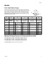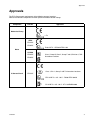
1
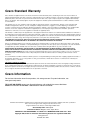
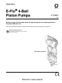
Operation
E-Flo® 4-Ball
Piston Pumps
311593N
EN
Durable, energy efficient piston pumps for high volume paint circulation applications.
For professional use only.
See page 3 for model information, including maximum working pressure. See page 5 for approvals.
Important Safety Instructions
Read all warnings and instructions in this manual.
Save these instructions.
E-Flo 4000 Pump Shown
ti8317c
Related Manuals
Contents
Related Manuals . . . . . . . . . . . . . . . . . . . . . . . . . . . 2
Models . . . . . . . . . . . . . . . . . . . . . . . . . . . . . . . . . . . 3
E-Flo 4-Ball Piston Pumps . . . . . . . . . . . . . . . . . 3
Maximum Working Pressure and
Pump Operational Limits . . . . . . . . . . . . . . . 3
Approvals . . . . . . . . . . . . . . . . . . . . . . . . . . . . . . . . . 5
Warnings . . . . . . . . . . . . . . . . . . . . . . . . . . . . . . . . . 6
Overview . . . . . . . . . . . . . . . . . . . . . . . . . . . . . . . . . . 8
Ground the System . . . . . . . . . . . . . . . . . . . . . . . . 11
Controls and Indicators . . . . . . . . . . . . . . . . . . . . 12
Variable Frequency Drive (VFD) . . . . . . . . . . . . 12
Local Control Box . . . . . . . . . . . . . . . . . . . . . . . 12
Setup . . . . . . . . . . . . . . . . . . . . . . . . . . . . . . . . . . . . 13
Fill gear reducer reservoir with oil . . . . . . . . . . . 13
Fill TSL Reservoirs . . . . . . . . . . . . . . . . . . . . . . 13
Flush before using equipment . . . . . . . . . . . . . . 13
Operation . . . . . . . . . . . . . . . . . . . . . . . . . . . . . . . . 14
Pressure Relief Procedure . . . . . . . . . . . . . . . . 14
Priming . . . . . . . . . . . . . . . . . . . . . . . . . . . . . . . 14
Startup . . . . . . . . . . . . . . . . . . . . . . . . . . . . . . . . 14
Shutdown . . . . . . . . . . . . . . . . . . . . . . . . . . . . . . 14
Maintenance . . . . . . . . . . . . . . . . . . . . . . . . . . . . . . 16
Preventive Maintenance Schedule . . . . . . . . . . 16
Check Gear Reducer Oil Level . . . . . . . . . . . . . 16
Gear Box and Drive Lubrication . . . . . . . . . . . . 16
Clean the Slider Cylinder Collectors . . . . . . . . . 16
Flushing . . . . . . . . . . . . . . . . . . . . . . . . . . . . . . . 17
Changing the TSL . . . . . . . . . . . . . . . . . . . . . . . 17
Technical Data . . . . . . . . . . . . . . . . . . . . . . . . . . . . 18
Graco Standard Warranty . . . . . . . . . . . . . . . . . . . 20
Graco Information . . . . . . . . . . . . . . . . . . . . . . . . . 20
Related Manuals
Manual
311592
311594
311595
311596
311603
3A0539
2
Description
E-Flo Installation Manual
E-Flo Repair-Parts Manual
Pneumatic Back Pressure Regulator
Variable Frequency Drive Instructions
Sensor Circuit Option
High-Flo Lowers
311593N
Models
Models
E-Flo 4-Ball Piston Pumps
Check your pump’s identification plate (ID) for the 6-digit part number of your
pump. Use the following matrix to define the construction of your pump, based
on the six digits. For example, Pump Part No. E P 2 1 6 0 represents electric
power (E), pump (P), 230/460V motor (2), sensor circuit installed (1), 2000 cc
MaxLife lower (6), and no stand installed (0). To order replacement parts, see
the Repair-Parts manual 311594.
ID
ti8912a
E
P
2
1
6
0
First Digit
Second Digit
Third Digit
Fourth Digit
Fifth Digit
Sixth Digit
Power
Source
Equipment
Style
Motor
Sensor Circuit
Lower Size
Stand Option
E (electric) P (pump)
0
No motor
0
1
230/400V, 5 HP,
ATEX
230/460V, 5 HP,
UL/CSA
230/400V, 3 HP,
ATEX
230/460V, 3 HP,
UL/CSA
1
2
3
4
No circuit
installed
Circuit installed
1
1000 cc Chrome
0
2
1500 cc Chrome
1
3
2000 cc Chrome
4
1000 cc MaxLife®
5
1500 cc MaxLife
6
7
8
2000 cc MaxLife
750 cc Chrome
750 cc MaxLife
No stand
installed
Stand
installed
Maximum Working Pressure and Pump Operational Limits
E-Flo 1500: 425 psi (2.93 MPa, 29.3 bar) Maximum Working Pressure
E-Flo 2000: 460 psi (3.22 MPa, 32.2 bar) Maximum Working Pressure
E-Flo 3000: 330 psi (2.31 MPa, 23.1 bar) Maximum Working Pressure
E-Flo 4000: 250 psi (1.75 MPa, 17.5 bar) Maximum Working Pressure
See Technical Data, page 18, for pressure and flow limits.
311593N
3
Models
4
311593N
Approvals
Approvals
The E-Flo Pump meets requirements of the following approval agencies.
Refer to the individual components for other specific hazardous location listings.
Component
Part No.
Approvals
Mechanical Pump
c T3
ATEX
EP1XXX
EP3XXX
Ex de IIC T4 - CESI 05 ATEX 110X
Motor
UL/CSA
EP2XXX
Class I, Group D, Class II, Group F and G, Division 1, T3B
Hazardous Locations
EP4XXX
Class 1, Div. 1, Group C & D T3 Hazardous Locations
IS Sensor Circuit
EPX1XX
EEx ib IIB Ta = 0°C - 50°C - FM 06 ATEX 0025U
Ex ib IIB Ta = 0°C - 50°C - KTL 13-KB4BO-0088
311593N
5
Warnings
Warnings
The following warnings are for the setup, use, grounding, maintenance, and repair of this equipment. The exclamation point symbol alerts you to a general warning and the hazard symbols refer to procedure-specific risks. When
these symbols appear in the body of this manual, refer back to these Warnings. Product-specific hazard symbols and
warnings not covered in this section may appear throughout the body of this manual where applicable.
WARNING
FIRE AND EXPLOSION HAZARD
Flammable fumes, such as solvent and paint fumes, in work area can ignite or explode. To help prevent
fire and explosion:
• Use equipment only in well ventilated area.
• Eliminate all ignition sources; such as pilot lights, cigarettes, portable electric lamps, and plastic drop
cloths (potential static arc).
• Keep work area free of debris, including solvent, rags and gasoline.
• Do not plug or unplug power cords, or turn power or light switches on or off when flammable fumes
are present.
• Ground all equipment in the work area. See Grounding instructions.
• Use only grounded hoses.
• Hold gun firmly to side of grounded pail when triggering into pail.
• If there is static sparking or you feel a shock, stop operation immediately. Do not use equipment
until you identify and correct the problem.
• Keep a working fire extinguisher in the work area.
Static charge may build up on plastic parts during cleaning and could discharge and ignite flammable
vapors. To help prevent fire and explosion:
•
Clean plastic parts only in a well ventilated area.
•
Do not clean with a dry cloth.
•
Do not operate electrostatic guns in equipment work area.
EQUIPMENT MISUSE HAZARD
Misuse can cause death or serious injury.
• Do not operate the unit when fatigued or under the influence of drugs or alcohol.
• Do not exceed the maximum working pressure or temperature rating of the lowest rated system
component. See Technical Data in all equipment manuals.
• Use fluids and solvents that are compatible with equipment wetted parts. See Technical Data in all
equipment manuals. Read fluid and solvent manufacturer’s warnings. For complete information
about your material, request MSDS forms from distributor or retailer.
• Check equipment daily. Repair or replace worn or damaged parts immediately with genuine manufacturer’s replacement parts only.
• Do not alter or modify equipment.
• Use equipment only for its intended purpose. Call your distributor for information.
• Route hoses and cables away from traffic areas, sharp edges, moving parts, and hot surfaces.
• Do not kink or over bend hoses or use hoses to pull equipment.
• Keep children and animals away from work area.
• Comply with all applicable safety regulations.
6
311593N
Warnings
WARNING
ELECTRIC SHOCK HAZARD
Improper grounding, setup, or usage of the system can cause electric shock.
• Turn off and disconnect power at main switch before disconnecting any cables and before servicing
equipment.
• Connect only to grounded power source.
• All electrical wiring must be done by a qualified electrician and comply with all local codes and
regulations.
PRESSURIZED EQUIPMENT HAZARD
Fluid from the gun/dispense valve, leaks, or ruptured components can splash in the eyes or on skin and
cause serious injury.
• Follow Pressure Relief Procedure in this manual, when you stop spraying and before cleaning,
checking, or servicing equipment.
• Tighten all fluid connections before operating the equipment.
• Check hoses, tubes, and couplings daily. Replace worn or damaged parts immediately.
MOVING PARTS HAZARD
Moving parts can pinch or amputate fingers and other body parts.
• Keep clear of moving parts.
• Do not operate equipment with protective guards or covers removed.
• Pressurized equipment can start without warning. Before checking, moving, or servicing equipment,
follow the Pressure Relief Procedure in this manual. Disconnect power or air supply.
TOXIC FLUID OR FUMES HAZARD
Toxic fluids or fumes can cause serious injury or death if splashed in the eyes or on skin, inhaled, or
swallowed.
• Read MSDS’s to know the specific hazards of the fluids you are using.
• Store hazardous fluid in approved containers, and dispose of it according to applicable guidelines.
• Always wear impervious gloves when spraying or cleaning equipment.
PERSONAL PROTECTIVE EQUIPMENT
You must wear appropriate protective equipment when operating, servicing, or when in the operating
area of the equipment to help protect you from serious injury, including eye injury, inhalation of toxic
fumes, burns, and hearing loss. This equipment includes but is not limited to:
• Protective eyewear
• Clothing and respirator as recommended by the fluid and solvent manufacturer
• Gloves
• Hearing protection
BURN HAZARD
Equipment surfaces and fluid that’s heated can become very hot during operation. To avoid severe
burns, do not touch hot fluid or equipment. Wait until equipment/fluid has cooled completely.
311593N
7
Overview
Overview
An electric motor (B) provides input to a 75:1 gear
reducer (GR), which drives two fluid pumps (FP). See
FIG. 1. The stroke positions of the two pumps are offset
to achieve consistent flow from the pump assembly. See
FIG. 2.
B
The optional sensor circuit includes a top dead center
(TDC) sensor which assists software in measuring
motor speed, and a pressure transducer (PT) with circuit
board, which measures fluid pressure at the pump outlet. The Graco VFD software mimics the effect of a camshaft, constantly adjusting motor speed to keep steady
fluid flow and achieve minimal pressure variation. The
output shaft of the gearbox and the connecting rods
experience the effect of the imaginary camshaft by
speeding up when the pressure drops (pump lower is at
a changeover) and slowing down when pressure
increases (both lowers are pumping).
GR
The VFD can be controlled by a local control box
mounted in the hazardous area, via communication protocol (such as modbus), or directly from the keypad.
TDC (behind
cover)
PT
FIG. 3 shows a layout of a typical North American system. The pump (A) may be controlled by a local control
box (C) mounted in the hazardous area, a variable frequency drive (D) mounted in the non-hazardous area, or
remotely from a computer (Y). See manual 311592 for
pump and accessory installation information.
FP
FP
ti8317c
FIG. 1. E-Flo Electric Circulation Pump
ti8321a
FIG. 2. Cutaway Showing Offset Stroke Positions
8
311593N
Overview
Non-Hazardous Area
F
D
E
V
H
Hazardous Area
N M
M C
B
W
A
Z
AB
AA
S
AC
Y
L
AD
T
U
X
G
Hazardous
Area
Entrance
K
J
R
Non-Hazardous Area
P
AD
Hazardous Area
ti8651c
FIG. 3: Typical Installation
Key:
A
E-Flo Electric Circulation Pump
B*
C*
D*
E**
F*
G*
H*
J**
K**
L**
M**
N**
P*
R**
S**
Explosion-Proof Electric Motor
Local Control Box
Variable Frequency Drive (VFD)
System Power Disconnect Switch
Electrical Noise Filter
Power Module
VFD/BPR Pneumatic Control Kit
Electric Power Cable, VFD to Electric Motor
Electric Control Cable, Local Control Box to VFD
Explosion-Proof Seal Fittings
Electric IS Control Cable, Power Module to Pump Sensor
Circuit
Electric Cable, VFD to 3-Way Solenoid Valve (2 meters
provided by Graco)
Pump Stand
Fluid Inlet Line
Fluid Outlet Line
311593N
T** Fluid Return Line
U* Pneumatic Back Pressure Regulator
V** Air Supply Lines to 3-Way Solenoid Valve
W** Air Line, Solenoid Valve to Back Pressure Regulator
X** Ethernet Cable, VFD to Computer
Y** Personal Computer
Z** Pump Ground Wire
AA* Explosion-Proof Electric Agitator
AB** Pressure Relief
AC* Fluid Filters
AD* Fluid Line Isolation Valves
* Option available from Graco.
** Supplied by integrator.
9
Overview
10
311593N
Ground the System
Ground the System
The equipment must be grounded. Grounding reduces
the risk of static and electric shock by providing an
escape wire for the electrical current due to static build
up or in the event of a short circuit.
•
Variable frequency drive: grounded through proper
connection to power source.
•
Local control box: follow your local code.
•
Fluid supply container: follow your local code.
•
Solvent pails used when flushing: follow your local
code. Use only metal pails, which are conductive,
placed on a grounded surface. Do not place pail on a
nonconductive surface, such as paper, plastic, or
cardboard, which interrupts grounding continuity.
Ground the following equipment:
•
Pump: use ground screw (GS) to attach a ground
wire (Z) to the pump. Tighten the screw securely.
Connect the other end of the ground wire to a true
earth ground.
Z
GS
311593N
ti9230a
11
Controls and Indicators
Controls and Indicators
Variable Frequency Drive (VFD)
Use a variable frequency drive (VFD) accessory to provide motor drive control to the pump. Graco supplies
accessory 240V and 480V VFDs that optimize pump
performance. See manual 311596.
120373 UL/CSA Control Box
Local Control Box
The local control box contains five controls. See FIG. 4.
Secure/Disable Switch
•
Push in to secure.
•
Pull out to disable.
SD
ST
Start/Stop Switch
•
Set to START to start pump.
•
Set to STOP to stop pump.
AR
LR
Alarm Reset Button
Press to clear an alarm.
JG
Local/Remote Switch
•
Set to LOCAL to control pump using local control
box.
•
Set to REMOTE to control pump from a PC in a
remote location.
120991 ATEX Control Box
Jog Button
Press to enter jog mode.
ST
SD
JG
AR
TI10719A
LR
FIG. 4: Local Control Box
12
311593N
Setup
Setup
Fill gear reducer reservoir with
oil
Open the fill cap (FC) and fill the gear reducer oil reservoir with 2 quarts (1.9 liters) of Graco 288414 Oil (twelve
1 quart bottles). Check the oil level in the sight glass
(SG) on the gear reducer housing. Do not overfill. See
FIG. 5.
Fill TSL Reservoirs
Part No. 206995 Throat Seal Liquid (TSL) carries residue from the pump rod into the reservoir. Fill the TSL
reservoirs (R) with Graco 206994 Throat Seal Liquid
(TSL). See FIG. 6. See Changing the TSL on page 17
for fill instructions.
NOTE: 2 quarts brings oil level above sight glass (SG)
when off, but level drops when operating.
FC
R
R
ti8915b
SG
FIG. 6. Fill TSL Reservoirs
ti8914a
FIG. 5. Oil Fill
311593N
Flush before using equipment
The equipment was tested with Stoddard Solvent, which
is left in the fluid passages to protect parts. To avoid
contaminating your fluid with solvent, flush the equipment with a compatible solvent or water before using the
equipment. See Flushing, page 17.
13
Operation
Operation
Pressure Relief Procedure
Priming
1. Open the back pressure regulator and any other
accumulators in the system.
2. Start the pump, see Startup.
System pressure can cause the pump to cycle unexpectedly, which could result in serious injury from
splashing or moving parts.
3. Set START/STOP switch (ST) to STOP. See FIG. 4.
4. Set the back pressure regulator as desired. The
system is ready to run.
1. Set START/STOP switch (ST) to STOP. See FIG. 4.
2. Push in SECURE DISABLE (SD) switch.
Startup
3. Open the back pressure regulator and all fluid drain
valves in the system, having a waste container
ready to catch drainage. Leave open until you are
ready to pressurize system again.
1. Close the main power disconnect.
4. Check that pressure gauges on fluid supply and
return lines read zero. If gauges do not read zero,
determine cause and carefully relieve pressure by
VERY SLOWLY loosening a fitting. Clear obstruction before pressurizing system again.
2. Use the VFD to set motor to a low flow (approximately 15 Hz). Adjust as needed. See VFD manual
311596 for specific flow set procedure.
3. Push in SECURE DISABLE (SD) switch.
4. Set START/STOP switch (ST) to STOP. See FIG. 4.
5. Pull the SECURE DISABLE switch (SD) out to disengage it.
6. Set the motor speed on the VFD to achieve the
desired flow rate (see FIG. 7).
NOTICE
Do not exceed a motor speed of 60 Hz for more than 3
minutes.
7. Set START/STOP switch (ST) to START. The speed
will ramp up; it is not an immediate change.
8. Set BPR to obtain desired line pressure.
Shutdown
Relieve pressure, page 14.
14
311593N
Operation
Pump Cycles per Minute
gpm (lpm)
4
8
12
Key:
16
20
24
30 (114)
A
B
C
D
750 cc Pumps
1000 cc Pumps
1500 cc Pumps
2000 cc Pumps
25 (95)
D
Flow Rate
20 (76)
C
15 (57)
B
10 (38)
A
5 (19)
0
0
10
(300)
20
(600)
30
(900)
40
(1200)
50
(1500)
60
(1800)
Motor Speed in Hz (rpm)
Equations for each line:
2000 cc
Flow (gpm) = 1.13 x
30 x VFD (Hz)
1500 cc
Flow (gpm) = 0.811 x
30 x VFD (Hz)
75.16
75.16
1000 cc
Flow (gpm) = 0.598 x
30 x VFD (Hz)
75.16
750 cc
Flow (gpm) = 0.406 x
30 x VFD (Hz)
75.16
FIG. 7: Motor Speed and Flow Chart
311593N
15
Maintenance
Maintenance
Preventive Maintenance
Schedule
Establish a preventive maintenance schedule based on
the equipment’s repair history.
Check Gear Reducer Oil Level
NOTE: A faint clicking may be heard while the motor is
running. This is normal and is due to necessary clearances between the coupler (28), motor shaft, and motor
key. If the intensity increases significantly over time, it
could indicate the coupler is wearing and should be
replaced. Do not open the gear reducer. The gear
reducer is not field serviceable beyond the maintenance
recommended in this manual
Every day, check the oil level in the sight glass (SG) on
the gear reducer, with the motor running. Oil level (with
motor running) should fall between top and bottom of
the sight glass (SG). Open the fill cap (FC) and fill the
gear reducer oil reservoir as required with Graco
288414 Oil (package includes twelve 1 quart bottles).
Do not overfill. See FIG. 8.
X
GZ
GZ
7a
ti8717a
FC
FIG. 9. Lubricate Wrist Pin Bearing Every 6 Months
Clean the Slider Cylinder
Collectors
SG
ti8914a
FIG. 8. Oil Fill
Gear Box and Drive Lubrication
Every month, check the slider cylinder collectors for dirt
or debris. Remove the 2-piece shield covering the coupling assembly. Loosen the three set screws (SS) on the
collector (CL). Lower the collector and wipe the inside
with a clean, damp cloth. Return the collector to its operating position. Tighten the screws finger tight. Reinstall
the shields.
Replace the gear box lubricant after a break-in period of
200,000-300,000 cycles. Order 288414 Replacement
Oil.
Following the break-in period, replace the gear box lubricant once a year.
See FIG. 9. Every 6 months, lubricate the wrist pin bearing (7a) on the connecting rod with 1 shot (1 cc) of
107411 Grease or equivalent, using grease zerk (GZ).
Replace both wrist pin bearings annually. Order Wrist
Pin Replacement Kit 255216. Lubricate the crank pin
bearing (X) annually, using grease zerk (GZ).
16
CL
SS
ti9539a
FIG. 10. Slider Cylinder Collector
311593N
Maintenance
Flushing
How long TSL lasts depends on which chemicals are
used, how much is used, what pressure, and condition
of the pump seal and rod.
•
Flush before changing colors, before storing, and
before repairing equipment.
•
Flush at the lowest pressure possible. Check connectors for leaks and tighten as necessary.
•
Flush with a fluid that is compatible with the fluid
being dispensed and the equipment wetted parts.
A drop in the level of TSL in the reservoir indicates that
the throat packings are starting to wear. Add TSL to the
reservoir and keep the level above the Minimum fill line.
Monitor the usage and condition of the TSL. If pumped
material bypasses the throat packings and enters the
TSL reservoir, replace the packings.
To change the TSL:
1. Shut off the pump.
1. Follow Pressure Relief Procedure, page 14.
2. Supply the appropriate flushing material to the system.
3. Set pump to lowest possible fluid pressure, and start
the pump.
4. Flush long enough to thoroughly clean the system.
5. Follow Pressure Relief Procedure, page 14.
To avoid the buildup of static charge, do not rub the
plastic bottle with a dry cloth while it is attached to the
pump. Remove the bottle to clean, if needed.
2. Remove and empty the reservoir bottle. Clean any
residue.
Changing the TSL
Check the condition of the TSL and the level in the reservoir every week, minimum. TSL should be changed at
least every month.
Part No. 206995 Throat Seal Liquid (TSL) carries residue from the pump rod into the reservoir. Discoloration
of the TSL fluid is to be expected during normal operation. After some time the TSL will thicken and darken,
and must be replaced. Thick, dirty TSL will not pump
through the lines and will harden in the pump wet-cup.
3. Clean screen (Z) of inlet check valve (VI). If check
valves are not sealing and dirty TSL is getting into
the wet-cup, replace the check valves (VI, VO). See
FIG. 11.
4. Fill the reservoir to the Maximum fill line with Throat
Seal Liquid (TSL).
5. Run pump. Each time pump rod reaches bottom of
stroke, check that some TSL is pumped from reservoir through wet-cup and back to reservoir.
Maximum Fill Line
VO
Minimum Fill Line
VI
Z
TI15853a
TI15857a
FIG. 11. Cutaway of TSL Reservoir, and Fill Lines
311593N
17
Technical Data
Technical Data
Maximum Working Pressure . . . . . . . . . . . . . .
Maximum Fluid Temperature . . . . . . . . . . . . . .
Electrical Requirements . . . . . . . . . . . . . . . . . .
Ambient Temperature Range . . . . . . . . . . . . . .
Maximum Fluid Output . . . . . . . . . . . . . . . . . . .
Fluid Inlet and Outlet Size . . . . . . . . . . . . . . . .
Gear Reducer Oil Capacity . . . . . . . . . . . . . . .
Required Gear Reducer Lubricant . . . . . . . . . .
Weight (with motor and 2000 cc lowers) . . . . .
Wetted Parts . . . . . . . . . . . . . . . . . . . . . . . . . .
Electric Motor . . . . . . . . . . . . . . . . . . . . . . . . . .
Maximum Production Motor Speed . . . . . . . . .
Maximum Motor Torque . . . . . . . . . . . . . . . . . .
Gear Reduction Ratio. . . . . . . . . . . . . . . . . . . .
18
E-Flo 1500: 425 psi (2.93 MPa, 29.3 bar)
E-Flo 2000: 460 psi (3.22 MPa, 32.2 bar)
E-Flo 3000: 330 psi (2.31 MPa, 23.1 bar)
E-Flo 4000: 250 psi (1.75 MPa, 17.5 bar)
150°F (66°C)
European Models: 230/400 Vac, 3 phase, 20 A/15 A
North American Models: 230/460 Vac, 3 phase, 20 A/15 A
32-104°F (0-40°C)
See charts on page 19.
2 in. Tri-clamp
2 quarts (1.9 liters)
ISO VG220 grade oil (Graco Part No. 288414)
Pump: 550 lb (249 kg)
Lower: see manual 3A0539
300 Series SST, CV-75, 17-4 PH SST, PTFE
E-Flo 1500: 3 HP, 1800 rpm (60 Hz) or 1500 rpm (50 Hz), NEMA
182 TC Frame
E-Flo 2000/3000/4000: 5 HP, 1800 rpm (60 Hz) or 1500 rpm (50
Hz), NEMA 184 TC Frame
1500 rpm (50 Hz)
1800 rpm (60 Hz)
E-Flo 1500: 9.1 ft-lb (12.3 N•m)
E-Flo 2000/3000/4000: 15 ft-lb (20.3 N•m)
75.16:1
311593N
Technical Data
psi (MPa, bar)
Pressure and Flow Capability of E-Flo Family with 50 Hz Motor
(continuous production use)
500 (3.50, 35.0)
Key:
450 (3.15, 31.5)
A
B
C
D
B
A
400 (2.80, 28.0)
C
E-Flo 1500
E-Flo 2000
E-Flo 3000
E-Flo 4000
350 (2.41, 24.1)
Fluid Pressure
D
300 (2.10, 21.0)
250 (1.72, 17.2)
200 (1.4, 14.0)
150 (1.03, 10.3)
100 (0.70, 7.0)
50 (0.35, 3.5)
0
25
(95)
20
(76)
15
(57)
10
(38)
5
(19)
Fluid Flow in gpm (lpm)
psi (MPa, bar)
Pressure and Flow Capability of E-Flo Family with 60 Hz Motor
(continuous production use)
500 (3.50, 35.0)
Key:
450 (3.15, 31.5)
A
A
B
C
D
B
400 (2.80, 28.0)
C
E-Flo 1500
E-Flo 2000
E-Flo 3000
E-Flo 4000
350 (2.41, 24.1)
Fluid Pressure
D
300 (2.10, 21.0)
250 (1.72, 17.2)
200 (1.4, 14.0)
150 (1.03, 10.3)
100 (0.70, 7.0)
50 (0.35, 3.5)
0
5
(19)
10
(38)
15
(57)
20
(76)
25
(95)
30
(114)
Fluid Flow in gpm (lpm)
311593N
19
Graco Standard Warranty
Graco warrants all equipment referenced in this document which is manufactured by Graco and bearing its name to be free from defects in
material and workmanship on the date of sale to the original purchaser for use. With the exception of any special, extended, or limited warranty
published by Graco, Graco will, for a period of twelve months from the date of sale, repair or replace any part of the equipment determined by
Graco to be defective. This warranty applies only when the equipment is installed, operated and maintained in accordance with Graco’s written
recommendations.
This warranty does not cover, and Graco shall not be liable for general wear and tear, or any malfunction, damage or wear caused by faulty
installation, misapplication, abrasion, corrosion, inadequate or improper maintenance, negligence, accident, tampering, or substitution of
non-Graco component parts. Nor shall Graco be liable for malfunction, damage or wear caused by the incompatibility of Graco equipment with
structures, accessories, equipment or materials not supplied by Graco, or the improper design, manufacture, installation, operation or
maintenance of structures, accessories, equipment or materials not supplied by Graco.
This warranty is conditioned upon the prepaid return of the equipment claimed to be defective to an authorized Graco distributor for verification of
the claimed defect. If the claimed defect is verified, Graco will repair or replace free of charge any defective parts. The equipment will be returned
to the original purchaser transportation prepaid. If inspection of the equipment does not disclose any defect in material or workmanship, repairs will
be made at a reasonable charge, which charges may include the costs of parts, labor, and transportation.
THIS WARRANTY IS EXCLUSIVE, AND IS IN LIEU OF ANY OTHER WARRANTIES, EXPRESS OR IMPLIED, INCLUDING BUT NOT LIMITED
TO WARRANTY OF MERCHANTABILITY OR WARRANTY OF FITNESS FOR A PARTICULAR PURPOSE.
Graco’s sole obligation and buyer’s sole remedy for any breach of warranty shall be as set forth above. The buyer agrees that no other remedy
(including, but not limited to, incidental or consequential damages for lost profits, lost sales, injury to person or property, or any other incidental or
consequential loss) shall be available. Any action for breach of warranty must be brought within two (2) years of the date of sale.
GRACO MAKES NO WARRANTY, AND DISCLAIMS ALL IMPLIED WARRANTIES OF MERCHANTABILITY AND FITNESS FOR A
PARTICULAR PURPOSE, IN CONNECTION WITH ACCESSORIES, EQUIPMENT, MATERIALS OR COMPONENTS SOLD BUT NOT
MANUFACTURED BY GRACO. These items sold, but not manufactured by Graco (such as electric motors, switches, hose, etc.), are subject to
the warranty, if any, of their manufacturer. Graco will provide purchaser with reasonable assistance in making any claim for breach of these
warranties.
In no event will Graco be liable for indirect, incidental, special or consequential damages resulting from Graco supplying equipment hereunder, or
the furnishing, performance, or use of any products or other goods sold hereto, whether due to a breach of contract, breach of warranty, the
negligence of Graco, or otherwise.
FOR GRACO CANADA CUSTOMERS
The Parties acknowledge that they have required that the present document, as well as all documents, notices and legal proceedings entered into,
given or instituted pursuant hereto or relating directly or indirectly hereto, be drawn up in English. Les parties reconnaissent avoir convenu que la
rédaction du présente document sera en Anglais, ainsi que tous documents, avis et procédures judiciaires exécutés, donnés ou intentés, à la suite
de ou en rapport, directement ou indirectement, avec les procédures concernées.
Graco Information
For the latest information about Graco products, visit www.graco.com. For patent information, see
www.graco.com/patents.
TO PLACE AN ORDER, contact your Graco distributor or call to identify the nearest distributor.
Phone: 612-623-6921 or Toll Free: 1-800-328-0211 Fax: 612-378-3505
All written and visual data contained in this document reflects the latest product information available at the time of publication.
Graco reserves the right to make changes at any time without notice.
Original instructions. This manual contains English. MM 311593
Graco Headquarters: Minneapolis
International Offices: Belgium, China, Japan, Korea
GRACO INC. AND SUBSIDIARIES • P.O. BOX 1441 • MINNEAPOLIS MN 55440-1441 • USA
Copyright 2007, Graco Inc. All Graco manufacturing locations are registered to ISO 9001.
www.graco.com
Revised June 2013