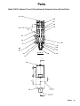
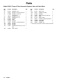
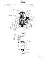
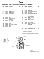
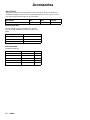
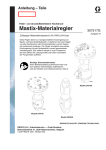
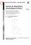
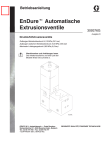
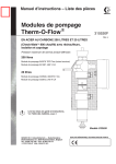
1
Instructions–Parts List
Therm–O–FlowR
Automatic Dispense Valves
310538M
EN
Air–operated dispense valves. For professional use only.
Important Safety Instructions
Read all warnings and instructions in this manual.
Save these instructions.
Model 918483 Shown
Table of Contents
List of Models . . . . . . . . . . . . . . . . . . . . . . . . . . . . . . . . . . 2
Warnings . . . . . . . . . . . . . . . . . . . . . . . . . . . . . . . . . . . . . . 3
Installation . . . . . . . . . . . . . . . . . . . . . . . . . . . . . . . . . . . . . 6
Troubleshooting . . . . . . . . . . . . . . . . . . . . . . . . . . . . . . . 10
Service . . . . . . . . . . . . . . . . . . . . . . . . . . . . . . . . . . . . . . 11
Parts . . . . . . . . . . . . . . . . . . . . . . . . . . . . . . . . . . . . . . . .
Accessories . . . . . . . . . . . . . . . . . . . . . . . . . . . . . . . . . .
Dimensions . . . . . . . . . . . . . . . . . . . . . . . . . . . . . . . . . . .
Technical Data . . . . . . . . . . . . . . . . . . . . . . . . . . . . . . . .
Graco Standard Warranty . . . . . . . . . . . . . . . . . . . . . .
Graco Information . . . . . . . . . . . . . . . . . . . . . . . . . . . . .
20
43
45
47
48
48
List of Models
Valve
Type
Part
No.
Type
Voltage /
Maximum Fluid Working
No. of Pins Pressure
TOF
194485
Snuff Back
120 V / 6
241 bar, 24 MPa (3500 psi) 10 bar, 1 MPa (150 psi)
20
TOF
918483
Snuff Back
120 V / 6
241 bar, 24 MPa (3500 psi) 10 bar, 1 MPa (150 psi)
22
918512
Snuff Back
Ambient
241 bar, 24 MPa (3500 psi) 10 bar, 1 MPa (150 psi)
24
TOF
918639
Snuff Back
120 V / 6
241 bar, 24 MPa (3500 psi) 10 bar, 1 MPa (150 psi)
26
TOF+
243694
Base Seal
240 V / 8
241 bar, 24 MPa (3500 psi) 10 bar, 1 MPa (150 psi)
28
TOF 200
297266
Snuff Back Swirl 240 V / 8
241 bar, 24 MPa (3500 psi) 10 bar, 1 MPa (150 psi)
30
TOF+
243695
Base Seal H.F.
240 V / 8
241 bar, 24 MPa (3500 psi) 10 bar, 1 MPa (150 psi)
31
TOF+
243696
Snuff Back
240 V / 8
241 bar, 24 MPa (3500 psi) 10 bar, 1 MPa (150 psi)
33
TOF
C27340
Base Seal
Ambient
241 bar, 24 MPa (3500 psi) 10 bar, 1 MPa (150 psi)
35
TOF
C34068
Base Seal
120 V / 6
241 bar, 24 MPa (3500 psi) 10 bar, 1 MPa (150 psi)
37
TOF
C34079
Base Seal
120 V / 6
241 bar, 24 MPa (3500 psi) 10 bar, 1 MPa (150 psi)
39
TOF
C50592
Base Seal
120 V / 6
241 bar, 24 MPa (3500 psi) 10 bar, 1 MPa (150 psi)
41
2
310538
Maximum Air Input
Pressure
Parts
Page
Warnings
The following Warnings are for the safe setup, use, grounding, maintenance, and repair of this equipment. The
exclamation point symbol alerts you to a general warning and the hazard symbols refer to procedure–specific risks.
Refer back to these Warnings. Additional product–specific warnings may be found throughout the body of this
manual where applicable.
WARNING
EQUIPMENT MISUSE HAZARD
INSTRUCTIONS
Equipment misuse can cause the equipment to rupture, malfunction, or start unexpectedly and
result in serious injury.
D This equipment is for professional use only.
D Read all instruction manuals, warnings, tags, and labels before operating the equipment.
D Use the equipment only for its intended purpose. If you are uncertain, call your Graco distributor.
D Do not alter or modify this equipment. Use only genuine Graco parts and accessories.
D Check the equipment daily. Repair or replace worn or damaged parts immediately.
D Do not exceed the maximum air working pressure of 1 MPa (10 bar, 150 psi) to the applicator.
D Do not exceed the maximum fluid working pressure of 24 MPa (241 bar, 3500 psi) to the
applicator or manifold.
D Never exceed the recommended working pressure or the maximum air inlet pressure stated on
your pump or in the Technical Data on page 47.
D Be sure that all spray/dispensing equipment and accessories are rated to withstand the maximum working pressure of the pump. Do not exceed the maximum working pressure of any
component or accessory used in the system.
D Route hoses away from traffic areas, sharp edges, moving parts, and hot surfaces.
D Do not expose Graco standard hoses to temperatures above 180_F (82_C) or below –40_F
(–40_C). Do not expose Graco electrically heated hoses to temperatures above 400° F
(222° C) or below –40_F (–40_C).
D Do not expose Graco standard hoses to temperatures above 180_F (82_C) or below –40_F
(–40_C).
D Do not use the hoses to pull the equipment.
D Use only fluids and solvents that are compatible with the equipment wetted parts. See the
Technical Data sections of all the equipment manuals. Read the fluid manufacturer’s warnings.
D Always wear protective eyewear, gloves, clothing, and respirator as recommended by the fluid
and solvent manufacturers.
D Wear hearing protection when operating this equipment.
D Comply with all applicable local, state and national fire, electrical and other safety regulations.
310538
3
WARNING
HOT SURFACE AND FLUID HAZARD
Heated fluid can cause severe burns and can cause equipment surfaces to become very hot.
D Wear protective gloves and clothing when operating this equipment in a heated system.
D Do not touch the metal heat sink when the surface is hot.
D Allow the equipment to cool thoroughly before servicing.
Some heated systems are designed to dispense Polyurethane (PUR) heated materials. PUR
systems are supplied with ventilation hoods, and require proper ventilation and specially designed
system components.
SKIN INJECTION HAZARD
Spray from the applicator, hose leaks, or ruptured components can inject fluid into your body and
cause extremely serious injury, including the need for amputation. Fluid splashed in the eyes or on
the skin can also cause serious injury.
D Fluid injected into the skin might look like just a cut, but it is a serious injury. Get immediate
surgical treatment.
D Do not point the applicator at anyone or at any part of the body.
D Do not put hand or fingers over the front of the applicator.
D Do not stop or deflect fluid leaks with your hand, body, glove, or rag.
D Follow the Pressure Relief Procedure on page 11 whenever you are instructed to: relieve
pressure; stop dispensing; clean, check, or service the equipment; or install or clean a tip or
nozzle.
D Tighten all the fluid connections before operating the equipment.
D Check the hoses, tubes, and couplings daily. Replace worn, damaged, or loose parts immediately. Permanently coupled hoses cannot be repaired; replace the entire hose.
D ALWAYS wear eye protection and protective clothing when installing, operating, or servicing this
dispensing equipment.
D Do not remove or modify any part of the applicator; this can cause a malfunction and result in
serious bodily injury.
D Use extreme caution when cleaning or changing tips. If the tip clogs while applying material,
ALWAYS follow the Pressure Relief Procedure on page 11, then remove the tip to clean it.
D NEVER wipe off build-up around the tip or air cap until pressure is fully relieved.
4
310538
WARNING
FIRE, EXPLOSION, AND ELECTRIC SHOCK HAZARD
Improper grounding, poor air ventilation, open flames, or sparks can cause a hazardous condition
and result in fire or explosion and serious injury.
D Ground the equipment and the object being sprayed. The Automatic Dispense Valve is
grounded through proper connection of pin E inside the electrical control panel to truth earth
ground inside the electrical control panel. See Grounding on page 9.
D Ground the equipment and the object being sprayed, and all other electrically conductive
objects in the dispense area. Proper grounding dissipates static electricity generated in the
equipment. See Grounding on page 9.
D Do not use this equipment with flammable liquids.
D Keep the dispense area free of debris, including solvent, rags, and gasoline.
D If there is any static sparking or you feel an electric shock while using the equipment, stop dispensing immediately. Do not use the equipment until you have identified and corrected the
problem.
D Make sure all electrical work is performed by a qualified electrician only.
D Have any checks, installation, or service to electrical equipment performed by a qualified electrician only.
D Make sure all electrical equipment is installed and operated in compliance with applicable
codes.
D Make sure power is disconnected when servicing and repairing equipment.
D Before operating the equipment, extinguish all open flames or pilot lights in the dispense area.
D Do not smoke in the dispensing area.
D Keep liquids away from the electrical components
D Disconnect electrical power at the main switch before servicing the equipment.
D Never exceed maximum wattage of the supply unit.
TOXIC FLUID HAZARD
Hazardous fluids or toxic fumes can cause serious injury or death if splashed in the eyes or on the
skin, swallowed, or inhaled.
D Provide fresh air ventilation to avoid the buildup of vapors from the fluid being dispensed.
D Know the specific hazards of the fluid you are using.
D Store hazardous fluid in an approved container. Dispose of hazardous fluid according to all
local, state and national guidelines.
D Always wear protective eyewear, gloves, clothing and respirator as recommended by the fluid
and solvent manufacturer.
D Avoid exposure to heated material fumes.
310538
5
Installation
Install the automatic applicator as follows:
D
D
D
D
D
D
Attach Dispense Tip, Nozzle, or Swirl
mount the automatic dispense valve
attach dispense tip, nozzle, or swirl
connect the air lines
connect material hose
connect the electrical cable
make sure the automatic dispense valve is
grounded
Attach a dispense tip and a nozzle adapter, or a nozzle
adapter alone, to the automatic dispense valve.
Dispense Tip and Nozzle Adapter Attachment
Mount the Automatic Dispense Valve
Mount the automatic dispense valve to the mounting
bracket on a stationary support or robotic arm (Fig. 1),
using two socket head screws (300) and two flat
washers (50). Be sure to position the insulation
block (280) and insulation tape (290) between the
dispense valve and the mounting bracket.
Attach dispense tip (B) to the automatic dispense
valve.
1. Select a nozzle adapter (C) and a dispensing
tip (B).
280
2. Install the tip and then use the nozzle adapter (C)
to secure the tip to the seat adapter (D).
50
300
D
A
B
290
C
Fig. 2
Fig. 1
6
310538
Installation
Nozzle Attachment
Swirl Nozzle Attachment
Attach a nozzle (C) to the automatic dispense valve.
1. Install swirl adapter (C) on seat adapter (D).
2. Install swirl applicator head (E).
1. Select a nozzle.
3. Install swirl nozzle (F).
2. Install nozzle adapter (C) on the seat adapter (D).
3. Install nozzle in nozzle adapter (E).
D
C
D
C
E
F
E
Fig. 3
Fig. 4
310538
7
Installation
Connect Air Lines to Dispense Valve
Connect Material Hose to Dispense Valve
Securely connect the material hose to the dispense
valve material inlet port (A). See Fig. 5.
CAUTION
Only use air fittings that are rated at a temperature
equal to or higher than the operating temperature of
your fluid dispensing system. Lower rated air fittings could melt and cause damage to the automatic dispense valve.
Connecting Electrical Cable to Dispense
Valve
Connect electrical cable plug from your Therm–O–
Flow or Therm–O–Flow Plus hose or control.
These valves are air to open and air to close with a
spring to bias them closed. Use a 4–way exhausting
solenoid to operate these valves.
Making sure to connect the appropriate air lines to the
appropriate ports (see Fig. 5), securely connect air
lines to dispense valve air ports (G).
1/8” npt
open
360
G
A
1/2” npt
close
1/8” npt
Snuff–Back Valve Shown
Fig. 5
8
310538
Installation
Ground the automatic dispense valve:
Grounding
WARNING
FIRE, EXPLOSION, AND ELECTRIC
SHOCK HAZARD
To reduce the risk of fire, explosion, or
electric shock:
1. Connect the connector from a heated hose to the
receptacle on the dispense valve.
Ground lead
coming from pin
E is fastened to
the bracket.
E
F
D
A
C
B
D The power source conduit is not an adequate ground for the system. The unit
must be grounded to either the building
ground or a true earth ground.
Fig. 6
3
2
1
7
6
D Also read and follow the warnings on page 5.
5
D Refer to your local code for the requirements for
a “true earth ground” in your area.
4
D A qualified electrician must complete
all grounding and wiring connections
and check the resistance.
Ground lead
coming from contact 8 to true
earth ground.
Fig. 7
TI0305
2. Connect the electrical cable to the electrical control
panel.
3. Verify that socket contact E on six pin models (see
Fig. 5) or contact eight on eight pin models (see
Fig. 7) , inside control panel receptacle, is connected to true earth ground.
310538
9
Troubleshooting
Some solutions require disassembling the automatic dispense valve. Always relieve system pressure before performing these procedures.
WARNING
To reduce the risk of serious injury whenever you are instructed to relieve pressure, always follow
the Pressure Relief Procedure (page 11).
See PARTS section for the parts that need to be serviced.
Problem
Cause(s)
Solution(s)
Air leaks from automatic dispense valve
l
Loose air connections
Check air connections.
Worn o-rings
Replace o-rings (90) and (100) in cylinder base.
Worn ring
Replace ring (110) in cylinder base.
Seal, spacer or retaining ring is worn
Replace rod seal (150), spacer (160),
and retaining ring (170).
Obstruction inside dispense valve
Remove seat adapter (10). Check and
replace if necessary, rod seal (150),
spacer (160), and retaining ring (170).
Worn needle
Check and replace needle (140), if
necessary.If replacing needle, you must
disassemble dispense valve.
Worn seat (Base seal models)
Check and replace seat (10) if necessary.
Material leaks from automatic
di
dispense
valve
l b
body
d
Seal not installed correctly
Seal is worn
Check seal (70) and replace if necessary.
Automatic dispense valve
does not shut off
Loose air connections
Check air connections.
Worn needle-seal interface
Check and replace, if necessary, needle
(140), rod seal (150), spacer (160), and
retaining ring (170).
Material leaks from front of
automatic dispense valve
If replacing needle, you must disassemble dispense valve
Automatic dispense valve
does not shut off
Worn spring-piston interface
Disassemble dispense valve. Check
and replace, if necessary, needle (140),
and spring (370).
Automatic dispense valve
does not shut off
Spring broken or not installed correctly
Disassemble dispense valve. Check
and replace, if necessary, needle (140),
and spring (370).
Automatic dispense valve
d
does
nott h
heatt material
t i l
Loose heater wires
Check and reconnect wire connections.
Loose sensor wires
Check and reconnect wire connections.
Heater unit failed
Replace heater. See page 17.
Sensor failed
Replace sensor. See page 17.
Temperature controller failed
Replace temperature controller.
No power to heating circuitry
Apply power to heating circuitry.
10
310538
Service
Pressure Relief Procedure
WARNING
HOT SURFACE AND FLUID HAZARD
The material and equipment will be
hot! To reduce risk of injury, wear eye
protection, gloves and protective clothing
when installing, operating, or servicing
this dispensing system.
SKIN INJECTION HAZARD
The system pressure must be manually
relieved to prevent the system from
starting or spraying accidentally. Fluid
under high pressure can be injected
through the skin and cause serious
injury. To reduce the risk of an injury
from injection, splashing fluid, or moving
parts, follow the Pressure Relief
Procedure whenever you:
D
D
D
D
are instructed to relieve the pressure
stop spraying/dispensing
install or clean the nozzle
check or service any of the system
equipment
This procedure describes how to relieve pressure from
the automatic dispense valve. See your supply unit or
system documentation for instructions on relieving
pressure for the entire dispensing system. Use this
procedure whenever you shut off the dispense valve
and before checking or adjusting any part of the
system, to reduce the risk of serious injury.
1. Shut off the material supply.
2. Shut off electrical power to the automatic dispense
valve.
3. Close all self bleeding air supply valves for supply
unit.
4. Have a container ready to catch the drainage, then
bleed off material pressure by actuating the dispense valve.
5. Shut off air supply to valve.
NOTE: If you suspect that the nozzle or hose is
completely clogged, or that pressure has not
been fully relieved after following the steps
above, very slowly loosen the tip guard,
retaining nut or hose end coupling to relieve
pressure gradually, then loosen completely. Then
clear the tip/nozzle or hose.
PRESSURIZED FLUID HAZARD
High pressures can cause serious personal injury. Be sure to open the dispense valve during system heat-up to
alleviate pressure which might occur in
the system due to material expansion.
310538
11
Service
Prepare to Service Automatic
Dispense Valve
If the unit is hot, determine whether or not you can
service the unit after it has cooled down. Some materials, like polyurethanes, may cure permanently when
cooled and exposed to air, preventing you from disassembling the dispense valve. If you are working with
such a material, service the unit while the material is at
a temperature where the material is soft enough to
work with. If the material can be reheated at a later
time, you can service the unit after it has cooled,
reheating the material as necessary.
Perform this procedure before servicing the automatic
dispense valve.
1. Relieve the system pressure.
WARNING
To reduce the risk of serious injury, whenever you
are instructed to relieve pressure, always follow the
Pressure Relief Procedure (page 11).
2. Make sure material flow has been shut off.
3. Make sure system air has been shut off.
12
310538
4. Remove power from the automatic dispense valve.
WARNING
HOT SURFACE AND FLUID HAZARD
The material and equipment will be
hot! To reduce risk of injury, wear eye
protection, gloves and protective clothing
when servicing this dispensing system
component.
5. If the material in the dispense valve can be reheated, wait for the dispense valve to cool thoroughly before servicing it.
If the material in the dispense valve cures permanently when cooled and/or exposed to air, service
the unit while the material is at a temperature
where the material is soft enough to work with.
Service
Service the Automatic Dispense Valve
Some dispense valve seals and o-rings can be replaced while the dispense valve is still mounted.
However, to replace the needle, you must remove the
automatic dispense valve from the mounting bracket
and disassemble it.
Prior to installation, lubricate all seals and o-rings with
115982 Graco thermal lubricant (3 oz. cartridge) or an
equivalent lubricant. Check with the material supplier
for a compatible lubricant.
Disconnect Automatic Dispense Valve from
Mounting Bracket
Remove the automatic dispense valve from its mounting bracket.
1. Perform the procedures in Prepare to Service
Automatic Dispense Valve on page 12.
WARNING
HOT SURFACE AND FLUID HAZARD
The material and equipment may be
hot! To reduce risk of injury, wear eye
protection, gloves and protective clothing
when servicing this dispensing system
component.
50
300
2. Disconnect the cable plug from receptacle on
dispense valve (H). See Fig. 8 on page 13.
3. Disconnect air lines from dispense valve air
ports (G).
A
4. Disconnect material hose from material inlet
port (A).
5. Separate the dispense valve body from the temperature conditioning manifold if used:
G
H
Reconnect Automatic Dispense Valve to Mounting
Bracket
Reconnect the automatic dispense valve to its mounting bracket. See Fig. 8.
1. Reconnect air lines to dispense valve air ports (G).
2. Reconnect the electrical cable plug to the receptacle (H).
Fig. 8
Snuff–Back Valve Shown
3. Reconnect the material hose to the dispense valve
material inlet port (A).
310538
13
Service
3. Remove the cable plug from the automatic dispense valve.
Disassemble Automatic Dispense Valve
310
260
a. Remove the two screws (230) from the connector cover. Then remove the connector
cover.
250
90
370
390
190
240
70
b. Remove the two socket head screws [Fig. 9,
Item (200)], two washers (210).The heater
cartridge (270) and
sensor (320) will come out of the dispense
valve body (Fig. 15).
4. Remove the four socket head screws (310) and
pull cylinder cap (260) and cylinder base (240)
from the dispense valve body (190). The needle
and piston remain with the cap and base.
A
140
5. Remove cap from base.
30
Fig. 9
200
210
230
Snuff–Back Valve Shown
To disassemble the automatic dispense valve:
1. Relieve automatic dispense valve pressure.
WARNING
To reduce the risk of serious injury whenever you
are instructed to relieve pressure, always follow the
Pressure Relief Procedure (page 11).
2. Make sure you have removed the dispense valve
from its mounting.
14
310538
6. Remove needle from either the cap or the base
(depending on which piece it went with.) When the
needle is separated from the base, the closure
spring (370) falls out.
7. Using an o-ring pick, remove dispense valve body
seal (70).
Service
Reassemble Automatic Dispense Valve
8. Disassemble adapter assembly (Fig. 10):
a. Unscrew nozzle adapter (C).
b. Remove three socket head screws (30 in
Fig. 9).
Prior to installation, lubricate all seals and o-rings with
115982 Graco high temperature grease (3 oz. cartridge), or an equivalent lubricant. Check with the
material supplier for a compatible lubricant.
c.
To reassemble the automatic dispense valve:
Remove seat adapter (10). Contains seat on
base seal valves.
d. Remove retaining ring (170) from adapter seat
(Fig. 10). Not on base seal guns.
1. Make sure all parts are free of solid material
residue.
e. Remove seal (150) and spacer (160) from
adapter seat (Fig. 10). Not on base seal guns.
2. Reassemble adapter assembly (Fig. 10):
f.
Remove o-ring (20) from adapter seat.
a. Lubricate and replace o-ring (20).
b. Lubricate and replace seal (150) and spacer
(160). Make sure the seal energizer faces
toward the material pressure.
70
c.
Replace retaining ring (170).
d. Replace seat retainer (10).
20
e. Insert and tighten three socket head screws
(30 in Fig. 9).
160
150
C
170
10
Fig. 10
Snuff–Back Valve Shown
f.
Screw on nozzle adapter (C).
3. Lubricate then replace dispense valve body
seal (70). Make sure the seal energizer faces
toward the material pressure.
310538
15
Service
4. Reassemble cap and base (Fig. 11):
a. Lubricate o-ring (100) and ring (110).
b. Insert o-ring (100) into needle piston (140)
groove.
c.
250
Slide ring (110) on top of o-ring (100).
d. Lubricate, then replace o-rings (90) and (250).
Insert spring on base seal models (Fig. 12).
90
e. Insert needle assembly into cylinder cap (260).
Base Seal Valves
Fig. 12
f.
Place spring (370) over shaft of needle/piston.
Seat spring in groove on piston face on snuff–
back models (Fig. 11).
g. Slide base (240), over the needle, into the
cylinder cap (260). Seat spring (370) in
groove on base.
5. Reconnect the cable receptacle to the automatic
dispense valve. See Fig. 13.
a. Re-insert heater cartridge and sensor into their
appropriate holes.
b. Ensure the ground wire (380) is connected to
the bracket (330).
c.
Connect the receptacle to the dispense valve
body. Then secure it with the two socket head
screws (200) and washers (210).
310
260
d. Reattach the receptacle cover . Then secure it
with the two screws (230).
390
100
110
140
250
370
240
90
Fig. 11
200
210
Snuff–Back Valve Shown
Fig. 13
16
310538
230
Service
Replace Heater Unit or Sensor
3. Remove old heater cartridge or sensor.
a. Locate the leads to the part you are replacing.
You can replace the automatic dispense valve heater
unit or sensor without removing the automatic dispense valve from its mounting bracket. You only have
to disconnect the cable connector from the automatic
dispense valve.
This procedure requires:
D
D
D
D
D
soldering iron
solder
shrink wrap
wire cutters
heat sink compound, Graco part number C07664 or
equivalent. Check with the material supplier for a
compatible compound.
b. Remove the shrink wrap from the leads.
c.
Unsolder the leads from the connector. Cut the
leads on 8 pin models, leaving enough to strip
and solder the leads.
4. Install new heater unit or sensor:
390
E
F
270
Heater
D
A
C
B
320
RTD Sensor
6 Pin 120 Volt
1. Perform the procedures in Preparing to Service
Automatic Dispense Valve on page 12.
Shown
Fig. 15
2. Remove the cable receptacle from the automatic
dispense valve.
a. Remove the two screws from the connector
cover [Fig. 9, Item (230)] and remove the
receptacle cover.
b. Remove the two socket head screws [Fig. 14,
Item (200)], two washers (210). The heater
cartridge (270) and sensor (320) will come out
of the dispense valve body.
2
200
210
270
320
Fig. 16
8 Pin 240 Volt Shown
Fig. 14
a. Install the shrink wrap over the leads.
310538
17
Service
b. Solder the leads to the appropriate connector
(Fig. 15) for 6 pin connector. For Therm–O–
Flow 8 pin assemblies, removal and replacement of the heaters and RTD require a pin
extraction tool, new pins, and a pin crimping
tool. These tools meet spec MIL–C–22520
[Ref. Daniels AF8 (crimp tool) or equivalent,
available at local electrical supply warehouse.
c.
Coat heater or sensor with heat sink compound.
Inspection Frequency
Automatic Dispense Valve
Inspect automatic dispense valve at least once every
two weeks for leakage or other visible damage.
Check specifically for:
D material leaks
D air leaks
Hoses/Tubes
Inspect hoses/tubes at least once every two weeks for
leakage or other visible damage.
d. Gently slide new heater or sensor into appropriate hole.
e. Either shrink the shrink wrap, or use electrical
tape to electrically insulate the connection
between the leads and connector pins.
5. Reconnect the dispense valve to the receptacle
(Figs. 14):
a. Reattach the receptacle base to the dispense
valve body and secure it with the two socket
head screws [Fig. 14, Items (200) and washer
(210)].
b. Reattach the receptacle cover to the Amphenol connector base and secure the cover with
the screws.
18
310538
D material hose
D air hoses
Heater
Every two weeks, check heater for proper resistance.
Resistance should be approximately 96 ohms for the
120 volt valves or 288 ohms (+30/–40) for the 240 volt
valves. Replace heater if necessary.
Also inspect heater when performing regular maintenance procedures.
Sensor
Every two weeks, check sensor resistance. Resistance should be 108 ohms at 21° C (70° F). Replace
sensor if necessary.
Also inspect sensor when performing regular maintenance procedures.
Parts
Model 194485, Warm (2755F/1355C max) Automatic Dispense Valve with Snuff Back
120 130
260
370
250
240
100 110
360
Cyl. air ports
1/8 npt
230
220
90
200 210
80
190
70
170
60
180
160
50
40
30
150
SECTION A–A
20
140
Ref. Nozzle
Adapter
10
A
310
300
50
290
280
360
350
B
B
Material Inlet
Port 1/2 npt
30
5/8 – 18 external thread
A
310538
19
Parts
Model 194485, Warm (2755F/1355C max) Automatic Dispense Valve with Snuff Back
Ref
No.
10
20*
30
Part No.
Description
Qty.
617479
722834
C19800
1
1
5
40
50
60
70*
80
90*
100*
110*
120
100016
111591
C34044
551190
C34030
113944
103649
C32088
617495
130*
140n
150*
160
170*
180
190
200
C20521
918471
C54172
617480
C20406
C34045
194527
112166
210
C19197
ADAPTER, seat
O–RING, –018 fluoroelastomer
SCREW, soc. hd. cap,
1/4”–20 x 0.5
WASHER, lock, 1/4”
WASHER, flat, 1/4”
PLATE, blank–off
SEAL, Polymite
SPACER
O–RING, –125 fluoroelastomer
O–RING, –123 fluoroelastomer
RING
SCREW, button head,
1/4”–20 x 0.31
SEAL, thread
NEEDLE, piston
SEAL, rod, 0.25 x 0.50 x 0.25
SPACER
RING, retaining, for 0.56 I.D.
SPACER
BODY, gun
SCREW, soc. hd. cap,
1/4”–20 x 0.75
WASHER, flat, 3/16
Ref
No.
220
230
Part No.
Description
Qty.
ÁÁÁ
ÁÁÁÁ
ÁÁÁÁÁÁÁÁÁÁ
ÁÁÁ
ÁÁÁÁ
ÁÁÁÁ
ÁÁÁÁÁÁÁÁÁÁ
ÁÁ
ÁÁÁÁ
ÁÁÁÁ
ÁÁÁÁÁÁÁÁÁÁ
ÁÁ
ÁÁÁ
ÁÁÁÁ
ÁÁÁÁÁÁÁÁÁÁ
ÁÁÁ
ÁÁÁ
ÁÁÁÁ
ÁÁÁÁÁÁÁÁÁÁ
ÁÁÁ
ÁÁÁÁ
ÁÁÁÁ
ÁÁÁÁÁÁÁÁÁÁ
ÁÁ
ÁÁÁ
ÁÁÁÁ
ÁÁÁÁ
ÁÁÁÁÁÁÁÁÁÁ
ÁÁ
ÁÁÁÁ
ÁÁÁÁÁÁÁÁÁÁ
ÁÁÁ
ÁÁÁÁÁÁÁÁÁÁÁÁÁÁÁÁÁ
ÁÁÁÁÁÁÁ
ÁÁÁÁ
ÁÁÁÁÁÁÁÁÁÁ
ÁÁ
ÁÁÁÁ
ÁÁÁÁ
ÁÁÁÁÁÁÁÁÁÁ
ÁÁ
ÁÁÁ
ÁÁÁÁ
ÁÁÁÁÁÁÁÁÁÁ
ÁÁÁ
ÁÁÁ
ÁÁÁÁ
ÁÁÁÁÁÁÁÁÁÁ
ÁÁÁ
ÁÁÁÁ
ÁÁÁÁÁÁÁÁÁÁ
ÁÁ
ÁÁÁÁ
ÁÁÁ
ÁÁÁÁ
ÁÁÁÁÁÁÁÁÁÁ
ÁÁÁ
ÁÁÁÁ
ÁÁÁÁ
ÁÁÁÁÁÁÁÁÁÁ
ÁÁ
ÁÁÁ
ÁÁÁÁ
ÁÁÁÁÁÁÁÁÁÁ
ÁÁÁ
ÁÁÁÁ
ÁÁÁÁ
ÁÁÁÁÁÁÁÁÁÁ
ÁÁ
ÁÁÁ
ÁÁÁÁ
ÁÁÁÁÁÁÁÁÁÁ
ÁÁÁ
ÁÁÁÁ
ÁÁÁÁ
ÁÁÁÁÁÁÁÁÁÁ
ÁÁ
ÁÁÁ
ÁÁÁÁ
ÁÁÁÁÁÁÁÁÁÁ
ÁÁÁ
ÁÁÁÁ
ÁÁÁÁ
ÁÁÁÁÁÁÁÁÁÁ
ÁÁ
ÁÁÁ
ÁÁÁÁ
ÁÁÁÁÁÁÁÁÁÁ
ÁÁÁ
ÁÁÁÁ
ÁÁÁÁÁÁÁÁÁÁ
ÁÁ
ÁÁÁÁ
ÁÁÁ
ÁÁÁÁ
ÁÁÁÁÁÁÁÁÁÁ
ÁÁÁ
ÁÁÁÁ
ÁÁÁÁ
ÁÁÁÁÁÁÁÁÁÁ
ÁÁ
ÁÁÁ
ÁÁÁÁ
ÁÁÁÁÁÁÁÁÁÁ
ÁÁÁ
ÁÁÁÁ
ÁÁÁÁ
ÁÁÁÁÁÁÁÁÁÁ
ÁÁ
ÁÁÁ
ÁÁÁÁ
ÁÁÁÁÁÁÁÁÁÁ
ÁÁÁ
ÁÁÁÁ
ÁÁÁÁ
ÁÁÁÁÁÁÁÁÁÁ
ÁÁ
ÁÁÁ
ÁÁÁÁ
ÁÁÁÁÁÁÁÁÁÁ
ÁÁÁ
ÁÁÁÁ
ÁÁÁÁ
ÁÁÁÁÁÁÁÁÁÁ
ÁÁ
ÁÁÁ
ÁÁÁÁ
ÁÁÁÁÁÁÁÁÁÁ
ÁÁÁ
ÁÁÁÁ
ÁÁÁÁ
ÁÁÁÁÁÁÁÁÁÁ
ÁÁ
ÁÁÁÁÁÁÁ
ÁÁÁÁÁÁÁÁÁÁ
ÁÁÁÁÁÁÁ
ÁÁÁÁ
ÁÁ
ÁÁÁÁ
ÁÁÁÁÁÁÁÁÁÁÁÁÁÁ
ÁÁÁÁÁÁÁÁÁÁ
ÁÁ
ÁÁÁÁ
ÁÁÁÁ
ÁÁÁÁÁÁÁÁÁÁ
ÁÁ
ÁÁÁÁ
ÁÁÁÁÁÁÁÁÁÁÁÁÁÁÁÁÁ
ÁÁÁÁ
ÁÁÁÁÁÁÁÁÁÁ
ÁÁ
ÁÁÁÁÁÁÁÁÁÁÁÁÁÁÁÁÁ
ÁÁÁÁÁÁÁÁÁÁÁÁÁÁÁÁÁ
COVER
1
SCREW, fill. hd. machine,
2
#4–40 x 0.25
240
617537
BASE, cylinder
1
250*
103337
O–RING, –010 fluoroelastomer 1
260
C34028
CAP, cylinder
1
270n
C31034
HEATER, cartridge 120V, 150
1
W
280
C32099
BLOCK, mounting
1
290
C33037
TAPE, fiberglass,
9”
0.5” wide (229 mm)
300
C19810
SCREW, soc. hd. cap,
2
1/4”–20 x 1
310
104594
SCREW, soc. hd. cap,
4
1/4”–20 x 3.25
320n
C32255
SENSOR, RTD
1
330
C34043
BRACKET
1
340
102794
NUT, hex, #4–40
4
350
C19270
SCREW, fill. hd. machine,
4
#4–40 x 0.38
360
C07329
CONNECTOR, 6 pin
1
370*
617536
SPRING
1
380
065345
WIRE, high temp, (127 mm)
5”
390
101674
TERMINAL, ring
1
400
C07664
COMPOUND, heat sink
A/R
460
112144
SCREW
1
510
157021
WASHER, lock
1
* These parts are included in Repair Kit 194486, which
may be purchased separately.
2
4
1
1
4
1
1
1
1
1
1
1
1
1
2
1
2
2
C34040
C19269
n Keep these spare parts on hand to reduce down time.
340
460
E
380
390
F
D
A
C
B
330
510
Ref.330
390
1
270
320
1
SECTION B–B (Enlarged to show detail)
Notes
1
20
310538
Coat with heat sink compound
(400) before installing.
Parts
Model 918483, Therm-O-Flow Automatic Dispense Valve with Snuff Back
120 130
260
370
250
240
100 110
360
Cyl. air ports
1/8 npt
230
220
90
200 210
80
190
70
170
60
180
160
50
40
30
150
SECTION A–A
20
140
10
A
310
300
50
290
280
360
350
B
B
Material Inlet
Port 1/2 npt
30
5/8–18m Material Outlet
A
310538
21
Parts
Model 918483, Therm-O-Flow Automatic Dispense Valve with Snuff Back
Ref
No.
10
20*
30
Part No.
Description
Qty.
617479
722834
C19800
1
1
5
40
50
60
70*
80
90*
100*
110*
120
100016
110755
C34044
617604
C34030
113944
103649
C32088
617495
130*
140n
150*
C20521
918471
617491
160
170*
180
190
200
617480
C20406
C34045
617605
112166
210
C19197
ADAPTER, seat
O–RING, –018 fluoroelastomer
SCREW, soc. hd. cap,
1/4”–20 x 0.5
WASHER, lock, 1/4”
WASHER, flat, 1/4”
PLATE, blank–off
SEAL
SPACER
O–RING, –125 fluoroelastomer
O–RING, –123 fluoroelastomer
RING
SCREW, button head,
1/4”–20 x 0.31
SEAL, thread
NEEDLE, piston
SEAL, rod hi temp,
0.25 x 0.50 x 0.25
SPACER
RING, retaining, for 0.56 I.D.
SPACER
BODY
SCREW, soc. hd. cap,
1/4”–20 x 0.75
WASHER, flat, 3/16
Ref
No.
220
230
Part No.
Description
Qty.
ÁÁÁ
ÁÁÁÁ
ÁÁÁÁÁÁÁÁÁÁ
ÁÁÁ
ÁÁÁÁ
ÁÁÁÁ
ÁÁÁÁÁÁÁÁÁÁ
ÁÁ
ÁÁÁÁ
ÁÁÁÁ
ÁÁÁÁÁÁÁÁÁÁ
ÁÁ
ÁÁÁ
ÁÁÁÁ
ÁÁÁÁÁÁÁÁÁÁ
ÁÁÁ
ÁÁÁ
ÁÁÁÁ
ÁÁÁÁÁÁÁÁÁÁ
ÁÁÁ
ÁÁÁÁ
ÁÁÁÁ
ÁÁÁÁÁÁÁÁÁÁ
ÁÁ
ÁÁÁ
ÁÁÁÁ
ÁÁÁÁ
ÁÁÁÁÁÁÁÁÁÁ
ÁÁ
ÁÁÁÁ
ÁÁÁÁÁÁÁÁÁÁ
ÁÁÁ
ÁÁÁÁÁÁÁÁÁÁÁÁÁÁÁÁÁ
ÁÁÁÁÁÁÁ
ÁÁÁÁ
ÁÁÁÁÁÁÁÁÁÁ
ÁÁ
ÁÁÁÁ
ÁÁÁÁ
ÁÁÁÁÁÁÁÁÁÁ
ÁÁ
ÁÁÁ
ÁÁÁÁ
ÁÁÁÁÁÁÁÁÁÁ
ÁÁÁ
ÁÁÁ
ÁÁÁÁ
ÁÁÁÁÁÁÁÁÁÁ
ÁÁÁ
ÁÁÁÁ
ÁÁÁÁÁÁÁÁÁÁ
ÁÁ
ÁÁÁÁ
ÁÁÁ
ÁÁÁÁ
ÁÁÁÁÁÁÁÁÁÁ
ÁÁÁ
ÁÁÁÁ
ÁÁÁÁ
ÁÁÁÁÁÁÁÁÁÁ
ÁÁ
ÁÁÁ
ÁÁÁÁ
ÁÁÁÁÁÁÁÁÁÁ
ÁÁÁ
ÁÁÁÁ
ÁÁÁÁ
ÁÁÁÁÁÁÁÁÁÁ
ÁÁ
ÁÁÁ
ÁÁÁÁ
ÁÁÁÁÁÁÁÁÁÁ
ÁÁÁ
ÁÁÁÁ
ÁÁÁÁ
ÁÁÁÁÁÁÁÁÁÁ
ÁÁ
ÁÁÁ
ÁÁÁÁ
ÁÁÁÁÁÁÁÁÁÁ
ÁÁÁ
ÁÁÁÁ
ÁÁÁÁ
ÁÁÁÁÁÁÁÁÁÁ
ÁÁ
ÁÁÁ
ÁÁÁÁ
ÁÁÁÁÁÁÁÁÁÁ
ÁÁÁ
ÁÁÁÁ
ÁÁÁÁÁÁÁÁÁÁ
ÁÁ
ÁÁÁÁ
ÁÁÁ
ÁÁÁÁ
ÁÁÁÁÁÁÁÁÁÁ
ÁÁÁ
ÁÁÁÁ
ÁÁÁÁ
ÁÁÁÁÁÁÁÁÁÁ
ÁÁ
ÁÁÁ
ÁÁÁÁ
ÁÁÁÁÁÁÁÁÁÁ
ÁÁÁ
ÁÁÁÁ
ÁÁÁÁ
ÁÁÁÁÁÁÁÁÁÁ
ÁÁ
ÁÁÁ
ÁÁÁÁ
ÁÁÁÁÁÁÁÁÁÁ
ÁÁÁ
ÁÁÁÁ
ÁÁÁÁ
ÁÁÁÁÁÁÁÁÁÁ
ÁÁ
ÁÁÁ
ÁÁÁÁ
ÁÁÁÁÁÁÁÁÁÁ
ÁÁÁ
ÁÁÁÁ
ÁÁÁÁ
ÁÁÁÁÁÁÁÁÁÁ
ÁÁ
ÁÁÁ
ÁÁÁÁ
ÁÁÁÁÁÁÁÁÁÁ
ÁÁÁ
ÁÁÁÁ
ÁÁÁÁ
ÁÁÁÁÁÁÁÁÁÁ
ÁÁ
ÁÁÁ
ÁÁÁ
ÁÁÁÁ
ÁÁ
ÁÁÁÁ
ÁÁÁÁÁÁÁÁÁÁÁÁÁÁ
ÁÁÁÁÁÁÁÁÁÁ
ÁÁ
ÁÁÁÁÁÁÁ
ÁÁÁÁÁÁÁÁÁÁÁÁÁÁ
ÁÁÁÁÁÁÁÁÁÁ
ÁÁÁÁÁÁÁ
ÁÁÁÁ
ÁÁÁÁ
ÁÁÁÁÁÁÁÁÁÁ
ÁÁ
ÁÁÁÁ
ÁÁÁÁÁÁÁÁÁÁÁÁÁÁÁÁÁ
ÁÁÁÁ
ÁÁÁÁÁÁÁÁÁÁ
ÁÁ
ÁÁÁÁÁÁÁÁÁÁÁÁÁÁÁÁÁ
ÁÁÁÁÁÁÁÁÁÁÁÁÁÁÁÁÁ
COVER
1
SCREW, fill. hd. machine,
2
#4–40 x 0.25
240
617603
BASE, cylinder
1
250*
103337
O–RING, –010 fluoroelastomer 1
260
C34028
CAP, cylinder
1
270n
C31034
HEATER, cartridge 120V, 150
1
W
280
C32099
BLOCK, mounting
1
290
C33037
TAPE, fiberglass,
9”
0.5” wide (229 mm)
300
C19810
SCREW, soc. hd. cap,
2
1/4”–20 x 1
310
104594
SCREW, soc. hd. cap,
4
1/4”–20 x 3.25
320n
C32255
SENSOR, RTD
1
330
C34043
BRACKET
1
340
102794
NUT, hex, #4–40
4
350
C19270
SCREW, fill. hd. machine,
4
#4–40 x 0.38
360
C07329
CONNECTOR, 6 pin
1
370*
617536
SPRING
1
380
065345
WIRE, high temp, (127 mm)
5”
390
101674
TERMINAL, ring
1
400
C07664
COMPOUND, heat sink
A/R
460
112144
SCREW
1
510
157021
WASHER, lock
1
* These parts are included in Repair Kit 918520, which
may be purchased separately.
2
4
1
1
4
1
1
1
1
1
1
1
1
1
2
1
2
2
C34040
C19269
n Keep these spare parts on hand to reduce down time.
340
460
E
390
380
F
D
A
C
B
330
510
Ref.330
390
320
1
1
270
SECTION B–B (Enlarged to show detail)
Notes
1
22
310538
Coat with heat sink compound
(400) before installing.
Parts
Model 918512, Ambient Therm-O-Flow Automatic Dispense Valve with Snuff Back
120 130
260
60
250
240
100 110
Cyl. air ports
1/8 npt
90
80
190
70
170
160
50
40
30
140
SECTION A–A
20
150
230
10
A
240
B
B
Material Inlet
Port 1/2 npt
30
1/8” npt female
material outlet
A
310538
23
Parts
Model 918512, Therm-O-Flow Automatic Dispense Valve with Snuff Back
Ref
No.
10
20
30
Part No.
Description
Qty.
617479
722834
C19800
1
1
5
40
50
60
70
80
90
100
110
120
100016
110755
617536
C34032
C34030
113944
103649
C32088
112925
130
C20521
ADAPTER, seat
O–RING, –018 fluoroelastomer
SCREW, soc. hd. cap,
1/4”–20 x 0.5
WASHER, lock, 1/4”
WASHER, flat, 1/4”
SPRING
SEAL
SPACER
O–RING, –123 fluoroelastomer
O–RING
O–RING
SCREW, button head, 1/4”–20 x
0.31
SEAL, thread
Ref
Part No. Description
Qty.
No.
140
617491
SEAL, outlet
1
150n
918471
NEEDLE assembly
1
160
617480
SPACER
1
170
111209
RING, retaining, for 0.56 I.D.
1
190
194527
BODY
1
200
617537
BASE, cylinder
1
210
103337
O–RING, –010 fluoroelastomer 1
220
C34028
CAP, cylinder
1
230
C32089
RETAINER
1
240
104594
SCREW, cap
4
n Keep these spare parts on hand to reduce down time.
ÁÁÁ
ÁÁÁÁ
ÁÁÁÁÁÁÁÁÁÁ
ÁÁÁ
ÁÁÁÁ
ÁÁÁÁ
ÁÁÁÁÁÁÁÁÁÁ
ÁÁ
ÁÁÁ
ÁÁÁÁ
ÁÁÁÁÁÁÁÁÁÁ
ÁÁÁ
ÁÁÁÁ
ÁÁÁÁ
ÁÁÁÁÁÁÁÁÁÁ
ÁÁ
ÁÁÁ
ÁÁÁÁ
ÁÁÁÁÁÁÁÁÁÁ
ÁÁÁ
ÁÁÁÁ
ÁÁÁÁ
ÁÁÁÁÁÁÁÁÁÁ
ÁÁ
ÁÁÁ
ÁÁÁÁ
ÁÁÁÁÁÁÁÁÁÁ
ÁÁÁ
ÁÁÁÁ
ÁÁÁÁ
ÁÁÁÁÁÁÁÁÁÁ
ÁÁ
ÁÁÁÁÁÁÁÁÁÁÁÁÁÁÁÁÁ
ÁÁÁÁÁÁÁ
ÁÁÁÁÁÁÁÁÁÁÁÁÁÁ
ÁÁ
ÁÁÁ
ÁÁÁÁ
ÁÁÁÁÁÁÁÁÁÁ
ÁÁÁ
ÁÁÁÁ
ÁÁÁÁ
ÁÁÁÁÁÁÁÁÁÁ
ÁÁ
ÁÁÁ
ÁÁÁÁ
ÁÁÁÁÁÁÁÁÁÁ
ÁÁÁ
ÁÁÁÁ
ÁÁÁÁ
ÁÁÁÁÁÁÁÁÁÁ
ÁÁ
ÁÁÁ
ÁÁÁÁ
ÁÁÁÁÁÁÁÁÁÁ
ÁÁÁ
ÁÁÁÁÁÁÁÁÁÁÁÁÁÁÁÁÁ
ÁÁÁÁ
ÁÁÁÁ
ÁÁÁÁÁÁÁÁÁÁ
ÁÁ
ÁÁÁ
ÁÁÁÁ
ÁÁÁÁÁÁÁÁÁÁ
ÁÁÁ
ÁÁÁÁÁÁÁÁÁÁÁÁÁÁÁÁÁ
ÁÁÁ
ÁÁÁÁ
ÁÁÁÁÁÁÁÁÁÁ
ÁÁÁ
ÁÁÁ
ÁÁÁ
ÁÁÁÁÁÁÁ
ÁÁÁÁÁÁÁÁÁÁÁÁÁÁ
ÁÁÁÁÁÁÁÁÁÁ
ÁÁÁ
24
310538
2
4
1
1
4
1
1
1
1
1
Parts
Model 918639, Therm-O-Flow Automatic Dispense Valve with Snuff Back
120 130
260
370
250
240
100 110
360
Cyl. air ports
1/8 npt
230
220
90
200 210
80
190
70
170
60
180
160
50
40
30
150
140
SECTION A–A
20
10
A
310
300
50
290
280
360
350
B
B
Material Inlet
Port 1/2 npt
30
#8 37° sae (3/4–16)
material outlet
A
310538
25
Parts
Model 918639, Therm-O-Flow Automatic Dispense Valve with Snuff Back
Ref
No.
10
20*
30
Part No.
Description
Qty.
617690
722834
C19800
1
1
5
40
50
60
70*
80
90*
100*
110*
120
100016
110755
C34044
617604
C34030
113944
103649
C32088
617495
130*
140n
150*
C20521
918471
617491
160
170*
180
190
200
617480
C20406
C34045
617605
112166
210
C19197
ADAPTER, nozzle/valve
O–RING, –018 fluoroelastomer
SCREW, soc. hd. cap,
1/4”–20 x 0.5
WASHER, lock, 1/4”
WASHER, flat, 1/4”
PLATE, blank–off
SEAL
SPACER
O–RING, –125 fluoroelastomer
O–RING, –123 fluoroelastomer
RING
SCREW, button head,
1/4”–20 x 0.31
SEAL, thread
NEEDLE, piston
SEAL, rod hi temp,
0.25 x 0.50 x 0.25
SPACER
RING, retaining, for 0.56 I.D.
SPACER
BODY
SCREW, soc. hd. cap,
1/4”–20 x 0.75
WASHER, flat, 3/16
Ref
No.
220
230
Part No.
Description
Qty.
ÁÁÁ
ÁÁÁÁ
ÁÁÁÁÁÁÁÁÁÁ
ÁÁÁ
ÁÁÁÁ
ÁÁÁÁ
ÁÁÁÁÁÁÁÁÁÁ
ÁÁ
ÁÁÁÁ
ÁÁÁÁ
ÁÁÁÁÁÁÁÁÁÁ
ÁÁ
ÁÁÁ
ÁÁÁÁ
ÁÁÁÁÁÁÁÁÁÁ
ÁÁÁ
ÁÁÁ
ÁÁÁÁ
ÁÁÁÁÁÁÁÁÁÁ
ÁÁÁ
ÁÁÁÁ
ÁÁÁÁ
ÁÁÁÁÁÁÁÁÁÁ
ÁÁ
ÁÁÁ
ÁÁÁÁ
ÁÁÁÁ
ÁÁÁÁÁÁÁÁÁÁ
ÁÁ
ÁÁÁÁ
ÁÁÁÁÁÁÁÁÁÁ
ÁÁÁ
ÁÁÁÁÁÁÁÁÁÁÁÁÁÁÁÁÁ
ÁÁÁÁÁÁÁ
ÁÁÁÁ
ÁÁÁÁÁÁÁÁÁÁ
ÁÁ
ÁÁÁÁ
ÁÁÁÁ
ÁÁÁÁÁÁÁÁÁÁ
ÁÁ
ÁÁÁ
ÁÁÁÁ
ÁÁÁÁÁÁÁÁÁÁ
ÁÁÁ
ÁÁÁ
ÁÁÁÁ
ÁÁÁÁÁÁÁÁÁÁ
ÁÁÁ
ÁÁÁÁ
ÁÁÁÁÁÁÁÁÁÁ
ÁÁ
ÁÁÁÁ
ÁÁÁ
ÁÁÁÁ
ÁÁÁÁÁÁÁÁÁÁ
ÁÁÁ
ÁÁÁÁ
ÁÁÁÁ
ÁÁÁÁÁÁÁÁÁÁ
ÁÁ
ÁÁÁ
ÁÁÁÁ
ÁÁÁÁÁÁÁÁÁÁ
ÁÁÁ
ÁÁÁÁ
ÁÁÁÁ
ÁÁÁÁÁÁÁÁÁÁ
ÁÁ
ÁÁÁ
ÁÁÁÁ
ÁÁÁÁÁÁÁÁÁÁ
ÁÁÁ
ÁÁÁÁ
ÁÁÁÁ
ÁÁÁÁÁÁÁÁÁÁ
ÁÁ
ÁÁÁ
ÁÁÁÁ
ÁÁÁÁÁÁÁÁÁÁ
ÁÁÁ
ÁÁÁÁ
ÁÁÁÁ
ÁÁÁÁÁÁÁÁÁÁ
ÁÁ
ÁÁÁ
ÁÁÁÁ
ÁÁÁÁÁÁÁÁÁÁ
ÁÁÁ
ÁÁÁÁ
ÁÁÁÁÁÁÁÁÁÁ
ÁÁ
ÁÁÁÁ
ÁÁÁ
ÁÁÁÁ
ÁÁÁÁÁÁÁÁÁÁ
ÁÁÁ
ÁÁÁÁ
ÁÁÁÁ
ÁÁÁÁÁÁÁÁÁÁ
ÁÁ
ÁÁÁ
ÁÁÁÁ
ÁÁÁÁÁÁÁÁÁÁ
ÁÁÁ
ÁÁÁÁ
ÁÁÁÁ
ÁÁÁÁÁÁÁÁÁÁ
ÁÁ
ÁÁÁ
ÁÁÁÁ
ÁÁÁÁÁÁÁÁÁÁ
ÁÁÁ
ÁÁÁÁ
ÁÁÁÁ
ÁÁÁÁÁÁÁÁÁÁ
ÁÁ
ÁÁÁ
ÁÁÁÁ
ÁÁÁÁÁÁÁÁÁÁ
ÁÁÁ
ÁÁÁÁ
ÁÁÁÁ
ÁÁÁÁÁÁÁÁÁÁ
ÁÁ
ÁÁÁ
ÁÁÁÁ
ÁÁÁÁÁÁÁÁÁÁ
ÁÁÁ
ÁÁÁÁ
ÁÁÁÁ
ÁÁÁÁÁÁÁÁÁÁ
ÁÁ
ÁÁÁ
ÁÁÁ
ÁÁÁÁ
ÁÁ
ÁÁÁÁ
ÁÁÁÁÁÁÁÁÁÁÁÁÁÁ
ÁÁÁÁÁÁÁÁÁÁ
ÁÁ
ÁÁÁÁÁÁÁ
ÁÁÁÁÁÁÁÁÁÁÁÁÁÁ
ÁÁÁÁÁÁÁÁÁÁ
ÁÁÁÁÁÁÁ
ÁÁÁÁ
ÁÁÁÁ
ÁÁÁÁÁÁÁÁÁÁ
ÁÁ
ÁÁÁÁ
ÁÁÁÁÁÁÁÁÁÁÁÁÁÁÁÁÁ
ÁÁÁÁ
ÁÁÁÁÁÁÁÁÁÁ
ÁÁ
ÁÁÁÁÁÁÁÁÁÁÁÁÁÁÁÁÁ
ÁÁÁÁÁÁÁÁÁÁÁÁÁÁÁÁÁ
COVER
1
SCREW, fill. hd. machine,
2
#4–40 x 0.25
240
617603
BASE, cylinder
1
250*
103337
O–RING, –010 fluoroelastomer 1
260
C34028
CAP, cylinder
1
270n
C31034
HEATER, cartridge 120V, 150
1
W
280
C32099
BLOCK, mounting
1
290
C33037
TAPE, fiberglass,
9”
0.5” wide (229 mm)
300
C19810
SCREW, soc. hd. cap,
2
1/4”–20 x 1
310
104594
SCREW, soc. hd. cap,
4
1/4”–20 x 3.25
320n
C32255
SENSOR, RTD
1
330
C34043
BRACKET
1
340
102794
NUT, hex, #4–40
4
350
C19270
SCREW, fill. hd. machine,
4
#4–40 x 0.38
360
C07329
CONNECTOR, 6 pin
1
370*
617536
SPRING
1
380
065345
WIRE, high temp, (127 mm)
5”
390
101674
TERMINAL, ring
1
400
C07664
COMPOUND, heat sink
A/R
460
112144
SCREW
1
510
157021
WASHER, lock
1
* These parts are included in Repair Kit 918520, which
may be purchased separately.
2
4
1
1
4
1
1
1
1
1
1
1
1
1
2
1
2
2
C34040
C19269
n Keep these spare parts on hand to reduce down time.
340
460
390
E
F
380
510
D
A
C
B
330
Ref.330
320
1
1
270
SECTION B–B (Enlarged to show detail)
Notes
1
26
310538
Coat with heat sink compound
(400) before installing.
Parts
Model 243694, Therm-O-Flow Automatic Dispense Valve
120, 130
125
260
370
250
360
430
100,110
Cyl. air ports
1/8 npt
240
230
220
90
200 210
80
70
190
20
60
140
TI0304
50, 40, 30
Section A–A
10
410
180
140
420
A
410
310
300
50
290
TI11204a
280
360
350
B
B
Material Inlet
Port 1/2 npt
30
1/8” npt female
material outlet
A
310538
27
Parts
Model 243694, Therm-O-Flow Automatic Dispense Valve
Ref
No.
10
20*
30
Part No.
Description
C32083
103610
C19800
40
50
60
70*
80
90*
100*
110*
120
125
130*
140n
180
190
200
100016
110755
C34044
C34032
C34030
113944
103649
C32088
112248
C19359
C20521
C32082
C34045
C32097
112166
210
220
230
C19197
C34040
C19269
ADAPTER, seat
O–RING, –018 fluoroelastomer
SCREW, soc. hd. cap,
1/4”–20 x 0.5
WASHER, lock, 1/4”
WASHER, flat, 1/4”
PLATE, blank–off
SEAL, graphite/PTFE
SPACER
O–RING, –125 fluoroelastomer
O–RING, –123 fluoroelastomer
RING
NUT, hex
SCREW, set
SEAL, thread
NEEDLE, assembly
SPACER
BODY
SCREW, soc. hd. cap,
1/4”–20 x 0.75
WASHER, flat, 3/16
COVER
SCREW, fill. hd. machine,
#4–40 x 0.25
Qty
.
1
1
5
Ref
No.
240
250*
260
270n
Part No.
Description
Qty
.
1
1
1
1
ÁÁÁ
ÁÁÁÁ
ÁÁÁÁÁÁÁÁÁÁ
ÁÁÁ
ÁÁÁÁ
ÁÁÁÁ
ÁÁÁÁÁÁÁÁÁÁ
ÁÁ
ÁÁÁ
ÁÁÁÁ
ÁÁÁÁÁÁÁÁÁÁ
ÁÁÁ
ÁÁÁÁ
ÁÁÁÁ
ÁÁÁÁÁÁÁÁÁÁ
ÁÁ
ÁÁÁ
ÁÁÁÁ
ÁÁÁÁÁÁÁÁÁÁ
ÁÁÁ
ÁÁÁÁ
ÁÁÁÁ
ÁÁÁÁÁÁÁÁÁÁ
ÁÁ
ÁÁÁ
ÁÁÁÁ
ÁÁÁÁÁÁÁÁÁÁ
ÁÁÁ
ÁÁÁÁ
ÁÁÁÁ
ÁÁÁÁÁÁÁÁÁÁ
ÁÁ
ÁÁÁÁÁÁÁÁÁÁÁÁÁÁÁÁÁ
ÁÁÁÁÁÁÁ
ÁÁÁÁ
ÁÁÁÁÁÁÁÁÁÁ
ÁÁ
ÁÁÁÁ
ÁÁÁÁ
ÁÁÁÁÁÁÁÁÁÁ
ÁÁ
ÁÁÁ
ÁÁÁÁ
ÁÁÁÁÁÁÁÁÁÁ
ÁÁÁ
ÁÁÁ
ÁÁÁÁ
ÁÁÁÁÁÁÁÁÁÁ
ÁÁÁ
ÁÁÁÁ
ÁÁÁÁÁÁÁÁÁÁ
ÁÁ
ÁÁÁÁ
ÁÁÁ
ÁÁÁÁ
ÁÁÁÁÁÁÁÁÁÁ
ÁÁÁ
ÁÁÁÁ
ÁÁÁÁ
ÁÁÁÁÁÁÁÁÁÁ
ÁÁ
ÁÁÁ
ÁÁÁÁ
ÁÁÁÁÁÁÁÁÁÁ
ÁÁÁ
ÁÁÁÁ
ÁÁÁÁ
ÁÁÁÁÁÁÁÁÁÁ
ÁÁ
ÁÁÁ
ÁÁÁÁ
ÁÁÁÁÁÁÁÁÁÁ
ÁÁÁ
ÁÁÁÁ
ÁÁÁÁ
ÁÁÁÁÁÁÁÁÁÁ
ÁÁ
ÁÁÁ
ÁÁÁÁ
ÁÁÁÁÁÁÁÁÁÁ
ÁÁÁ
ÁÁÁÁ
ÁÁÁÁ
ÁÁÁÁÁÁÁÁÁÁ
ÁÁ
ÁÁÁ
ÁÁÁÁ
ÁÁÁÁÁÁÁÁÁÁ
ÁÁÁ
ÁÁÁÁ
ÁÁÁÁ
ÁÁÁÁÁÁÁÁÁÁ
ÁÁ
ÁÁÁ
ÁÁÁÁ
ÁÁÁÁÁÁÁÁÁÁ
ÁÁÁ
ÁÁÁÁ
ÁÁÁÁ
ÁÁÁÁÁÁÁÁÁÁ
ÁÁ
ÁÁÁ
ÁÁÁÁ
ÁÁÁÁÁÁÁÁÁÁ
ÁÁÁ
ÁÁÁÁ
ÁÁÁÁ
ÁÁÁÁÁÁÁÁÁÁ
ÁÁ
ÁÁÁ
ÁÁÁÁ
ÁÁÁÁÁÁÁÁÁÁ
ÁÁÁ
ÁÁÁÁ
ÁÁÁÁ
ÁÁÁÁÁÁÁÁÁÁ
ÁÁ
ÁÁÁ
ÁÁÁÁ
ÁÁÁÁÁÁÁÁÁÁ
ÁÁÁ
ÁÁÁÁ
ÁÁÁÁ
ÁÁÁÁÁÁÁÁÁÁ
ÁÁ
ÁÁÁ
ÁÁÁÁ
ÁÁÁÁÁÁÁÁÁÁ
ÁÁÁ
ÁÁÁÁ
ÁÁÁÁ
ÁÁÁÁÁÁÁÁÁÁ
ÁÁ
ÁÁÁÁÁÁÁÁÁÁÁÁÁÁÁÁÁ
ÁÁÁÁÁÁÁ
ÁÁÁÁ
ÁÁ
ÁÁÁÁ
ÁÁÁÁÁÁÁÁÁÁÁÁÁÁ
ÁÁÁÁÁÁÁÁÁÁ
ÁÁ
ÁÁÁÁ
ÁÁÁÁ
ÁÁÁÁÁÁÁÁÁÁ
ÁÁ
ÁÁÁÁ
ÁÁÁÁÁÁÁÁÁÁÁÁÁÁÁÁÁ
ÁÁÁÁ
ÁÁÁÁÁÁÁÁÁÁ
ÁÁ
ÁÁÁÁÁÁÁÁÁÁÁÁÁÁÁÁÁ
ÁÁÁÁÁÁÁÁÁÁÁÁÁÁÁÁÁ
2
4
1
1
4
1
1
1
1
1
1
1
2
1
2
2
1
2
C32085
103337
C34028
116011
BASE, cylinder
O-RING, –010 fluoroelastomer
CAP, cylinder
HEATER, cartridge
230 V, 200 W
280
C32099 BLOCK, mounting
1
290
C33037 TAPE, fiberglass,
9”
0.5” wide (229 mm)
300
C19810 SCREW, soc. hd. cap,
2
1/4”–20 x 1
310
104594
SCREW, soc. hd. cap,
4
1/4”–20 x 3.25
320n C32255 SENSOR, RTD
1
330
C34043 BRACKET
1
350
C19949 SCREW, panhd. machine,
2
#4–40 x 0.5
360
115861
HOUSING, 8 pin
1
370
C34041 SPRING
1
380
065345
WIRE, high temp, (127 mm)
5”
390
101674
TERMINAL, ring
1
410
C32090 SEAT
1
420
C32089 NUT, retainer
1
430
115860
INSERT, male
1
440
115862
CONNECTOR, male, crimp
1
460
112144
SCREW, PH 8–32 X 1/4
1
510
157021
WASHER, lock
1
520
116640
CONNECTOR
4
* These parts are included in Repair Kit C27342, which
may be purchased separately.
n Keep these spare parts on hand to reduce down time.
Ref. 330 510 390
380, 440
460
2
1
270, 520
1
320, 520
SECTION B–B (Enlarged to show detail)
Notes
1
28
310538
Coat with heat sink compound
(400) before installing.
Parts
Model 297266, Automatic Hot Melt Swirl Dispense Valve
A
310
300, 50
290
360
280
350
125
B
B
120, 130
260
370
Material Inlet
Port 1/2 npt
30
360
250
90
430
240
80
230
A
50, 40, 30
220
70
380
60
200, 210
190
20
180
10
140
140
410
480
410
490
Section A–A
500
TI11205a
310538
29
Parts
Model 297266, Automatic Hot Melt Swirl Dispense Valve
Ref
No.
10
20*
30
Part No.
Description
Qty.
C32083
103610
C19800
1
1
5
40
50
60
70*
80
90*
100*
110*
120
125
130*
140n
180
190
200
100016
110755
C34044
C34032
C34030
113944
103649
C32088
112248
C19359
C20521
C32082
C34045
C32097
112166
210
220
230
C19197
C34040
C19269
ADAPTER, seat
O–RING, –018 fluoroelastomer
SCREW, soc. hd. cap,
1/4”–20 x 0.5
WASHER, lock, 1/4”
WASHER, flat, 1/4”
PLATE, blank–off
SEAL, graphite/PTFE
SPACER
O–RING, –125 fluoroelastomer
O–RING, –123 fluoroelastomer
RING
NUT, hex
SCREW, set
SEAL, thread
NEEDLE, assembly
SPACER
BODY
SCREW, soc. hd. cap,
1/4”–20 x 0.75
WASHER, flat, 3/16
COVER
SCREW, fill. hd. machine,
#4–40 x 0.25
Ref
No.
240
250*
260
270n
Part No.
Description
Qty.
ÁÁÁ
ÁÁÁÁ
ÁÁÁÁÁÁÁÁÁÁ
ÁÁÁ
ÁÁÁÁ
ÁÁÁÁ
ÁÁÁÁÁÁÁÁÁÁ
ÁÁ
ÁÁÁ
ÁÁÁÁ
ÁÁÁÁÁÁÁÁÁÁ
ÁÁÁ
ÁÁÁÁ
ÁÁÁÁ
ÁÁÁÁÁÁÁÁÁÁ
ÁÁ
ÁÁÁ
ÁÁÁÁ
ÁÁÁÁÁÁÁÁÁÁ
ÁÁÁ
ÁÁÁÁ
ÁÁÁÁ
ÁÁÁÁÁÁÁÁÁÁ
ÁÁ
ÁÁÁ
ÁÁÁÁ
ÁÁÁÁÁÁÁÁÁÁ
ÁÁÁ
ÁÁÁÁ
ÁÁÁÁ
ÁÁÁÁÁÁÁÁÁÁ
ÁÁ
ÁÁÁÁÁÁÁÁÁÁÁÁÁÁÁÁÁ
ÁÁÁÁÁÁÁ
ÁÁÁÁ
ÁÁÁÁÁÁÁÁÁÁ
ÁÁ
ÁÁÁÁ
ÁÁÁÁ
ÁÁÁÁÁÁÁÁÁÁ
ÁÁ
ÁÁÁ
ÁÁÁÁ
ÁÁÁÁÁÁÁÁÁÁ
ÁÁÁ
ÁÁÁ
ÁÁÁÁ
ÁÁÁÁÁÁÁÁÁÁ
ÁÁÁ
ÁÁÁÁ
ÁÁÁÁÁÁÁÁÁÁ
ÁÁ
ÁÁÁÁ
ÁÁÁ
ÁÁÁÁ
ÁÁÁÁÁÁÁÁÁÁ
ÁÁÁ
ÁÁÁÁ
ÁÁÁÁ
ÁÁÁÁÁÁÁÁÁÁ
ÁÁ
ÁÁÁ
ÁÁÁÁ
ÁÁÁÁÁÁÁÁÁÁ
ÁÁÁ
ÁÁÁÁ
ÁÁÁÁ
ÁÁÁÁÁÁÁÁÁÁ
ÁÁ
ÁÁÁÁ
ÁÁÁ
ÁÁÁÁ
ÁÁÁÁÁÁÁÁÁÁ
ÁÁÁ
ÁÁÁÁ
ÁÁÁÁÁÁÁÁÁÁ
ÁÁ
ÁÁÁ
ÁÁÁÁ
ÁÁÁÁÁÁÁÁÁÁ
ÁÁÁ
ÁÁÁÁ
ÁÁÁÁ
ÁÁÁÁÁÁÁÁÁÁ
ÁÁ
ÁÁÁ
ÁÁÁÁ
ÁÁÁÁÁÁÁÁÁÁ
ÁÁÁ
ÁÁÁÁ
ÁÁÁÁ
ÁÁÁÁÁÁÁÁÁÁ
ÁÁ
ÁÁÁ
ÁÁÁÁ
ÁÁÁÁÁÁÁÁÁÁ
ÁÁÁ
ÁÁÁÁ
ÁÁÁÁÁÁÁÁÁÁ
ÁÁ
ÁÁÁÁ
ÁÁÁ
ÁÁÁÁ
ÁÁÁÁÁÁÁÁÁÁ
ÁÁÁ
ÁÁÁÁ
ÁÁÁÁ
ÁÁÁÁÁÁÁÁÁÁ
ÁÁ
ÁÁÁ
ÁÁÁÁ
ÁÁÁÁÁÁÁÁÁÁ
ÁÁÁ
ÁÁÁÁ
ÁÁÁÁ
ÁÁÁÁÁÁÁÁÁÁ
ÁÁ
ÁÁÁ
ÁÁÁÁ
ÁÁÁÁÁÁÁÁÁÁ
ÁÁÁ
ÁÁÁÁ
ÁÁÁÁ
ÁÁÁÁÁÁÁÁÁÁ
ÁÁ
ÁÁÁ
ÁÁÁÁ
ÁÁÁÁÁÁÁÁÁÁ
ÁÁÁ
ÁÁÁÁ
ÁÁÁÁ
ÁÁÁÁÁÁÁÁÁÁ
ÁÁ
ÁÁÁ
ÁÁÁÁ
ÁÁÁÁÁÁÁÁÁÁ
ÁÁÁÁÁÁÁ
ÁÁÁÁ
ÁÁ
ÁÁÁÁ
ÁÁÁÁÁÁÁÁÁÁÁÁÁÁ
ÁÁÁÁÁÁÁÁÁÁ
ÁÁ
ÁÁÁÁÁÁÁ
ÁÁÁÁÁÁÁÁÁÁ
ÁÁÁ
ÁÁÁÁ
ÁÁÁÁ
ÁÁÁÁÁÁÁÁÁÁ
ÁÁ
ÁÁÁÁ
ÁÁÁÁ
ÁÁÁÁÁÁÁÁÁÁ
ÁÁ
ÁÁÁÁ
ÁÁÁÁÁÁÁÁÁÁÁÁÁÁÁÁÁ
ÁÁÁÁ
ÁÁÁÁÁÁÁÁÁÁ
ÁÁ
ÁÁÁÁÁÁÁÁÁÁÁÁÁÁÁÁÁ
ÁÁÁÁÁÁÁÁÁÁÁÁÁÁÁÁÁ
ÁÁÁÁÁÁÁÁÁÁÁÁÁÁÁÁÁ
BASE, cylinder
1
O-RING, –010 fluoroelastomer
1
CAP, cylinder
1
HEATER, cartridge
1
230 V, 200 W
280
C32099
BLOCK, mounting
1
290
C33037
TAPE, fiberglass,
9”
0.5” wide (229 mm)
300
C19810
SCREW, soc. hd. cap,
2
1/4”–20 x 1
310
104594
SCREW, soc. hd. cap,
4
1/4”–20 x 3.25
320n
C32255
SENSOR, RTD
1
330
C34043
BRACKET
1
350
C19949
SCREW, panhd. machine,
2
#4–40 x 0.5
360
115861
HOUSING, 8 pin
1
370
C34041
SPRING
1
380
065345
WIRE, high temp, (127 mm)
5”
390
101674
TERMINAL, ring
1
410
C32090
SEAT
1
430
115860
INSERT, male
1
440
115862
CONNECTOR, male, crimp
1
460
112144
SCREW, PH 8–32 X 1/4
1
480
15H098
ADAPTER, swirl
1
490
118072
HEAD. applicator, swirl
1
500
117950
NOZZLE, swirl, 0.30
1
510
157021
WASHER, lock
1
520
116640
CONNECTOR
4
* These parts are included in Repair Kit C27342, which
may be purchased separately.
2
4
1
1
4
1
1
1
1
1
1
1
2
1
2
2
1
2
C32085
103337
C34028
116011
n Keep these spare parts on hand to reduce down time.
1
320, 520
SENSOR RTD
1
380, 440
270, 520
HEATER
200W @ 240 VOLTS
Ref. 330
Notes
1
Coat with heat sink compound
before installing.
SECTION B–B (Enlarged to show detail)
30
310538
510
390
460
Parts
Model 243695, Therm-O-Flow Automatic Dispense Valve
120 130
125
260
370
250
Close
360
430
100,110
Cyl. air ports
1/8 npt
240
230
Open
220
90
200 210
80
190
70
60
140
180
140
TI0432
210, 40, 30
20
410
10
Ref. 1/2” npt(m) outlet
SECTION A–A
410
A
310
300
210
TI11206a
290
280
360
350
B
B
Material Inlet
Port 1/2 npt
30
1/2” npt male
material outlet
A
310538
31
Parts
Model 243695, Therm-O-Flow Automatic Dispense Valve
Ref
No.
10
20*
30
Part No.
Description
C51762
722834
C19800
40
50
60
70*
80
90*
100*
110*
120
125
130*
140n
150
160
170
180
190
200
100016
ADAPTER, seat
O–RING, –018 fluoroelastomer
SCREW, soc. hd. cap,
1/4”–20 x 0.5
WASHER, lock, 1/4”
C34044
C34032
C34030
113944
103649
C32088
112248
C19359
C20521
C32082
PLATE, blank–off
SEAL
SPACER
O–RING, –125 fluoroelastomer
O–RING, –123 fluoroelastomer
RING
NUT, hex
SCREW, set
SEAL, thread
NEEDLE, piston
1
1
4
1
1
1
1
1
1
1
C34045
C32097
112166
2
1
2
210
C19197
SPACER
BODY
SCREW, soc. hd. cap,
1/4”–20 x 0.75
WASHER, flat, 3/16
Ref
No.
220
230
Qty
.
1
1
5
Part No.
Description
Qty
.
1
2
ÁÁÁ
ÁÁÁÁ
ÁÁÁÁÁÁÁÁÁÁ
ÁÁÁ
ÁÁÁÁ
ÁÁÁÁ
ÁÁÁÁÁÁÁÁÁÁ
ÁÁ
ÁÁÁÁ
ÁÁÁÁ
ÁÁÁÁÁÁÁÁÁÁ
ÁÁ
ÁÁÁ
ÁÁÁÁ
ÁÁÁÁÁÁÁÁÁÁ
ÁÁÁ
ÁÁÁ
ÁÁÁÁ
ÁÁÁÁÁÁÁÁÁÁ
ÁÁÁ
ÁÁÁÁ
ÁÁÁÁ
ÁÁÁÁÁÁÁÁÁÁ
ÁÁ
ÁÁÁ
ÁÁÁÁ
ÁÁÁÁ
ÁÁÁÁÁÁÁÁÁÁ
ÁÁ
ÁÁÁÁ
ÁÁÁÁÁÁÁÁÁÁ
ÁÁÁ
ÁÁÁÁÁÁÁÁÁÁÁÁÁÁÁÁÁ
ÁÁÁÁÁÁÁ
ÁÁÁÁ
ÁÁÁÁÁÁÁÁÁÁ
ÁÁ
ÁÁÁÁ
ÁÁÁÁ
ÁÁÁÁÁÁÁÁÁÁ
ÁÁ
ÁÁÁ
ÁÁÁÁ
ÁÁÁÁÁÁÁÁÁÁ
ÁÁÁ
ÁÁÁ
ÁÁÁÁ
ÁÁÁÁÁÁÁÁÁÁ
ÁÁÁ
ÁÁÁÁ
ÁÁÁÁÁÁÁÁÁÁ
ÁÁ
ÁÁÁÁ
ÁÁÁ
ÁÁÁÁ
ÁÁÁÁÁÁÁÁÁÁ
ÁÁÁ
ÁÁÁÁ
ÁÁÁÁ
ÁÁÁÁÁÁÁÁÁÁ
ÁÁ
ÁÁÁ
ÁÁÁÁ
ÁÁÁÁÁÁÁÁÁÁ
ÁÁÁ
ÁÁÁÁ
ÁÁÁÁ
ÁÁÁÁÁÁÁÁÁÁ
ÁÁ
ÁÁÁ
ÁÁÁÁ
ÁÁÁÁÁÁÁÁÁÁ
ÁÁÁ
ÁÁÁÁ
ÁÁÁÁ
ÁÁÁÁÁÁÁÁÁÁ
ÁÁ
ÁÁÁ
ÁÁÁÁ
ÁÁÁÁÁÁÁÁÁÁ
ÁÁÁ
ÁÁÁÁ
ÁÁÁÁ
ÁÁÁÁÁÁÁÁÁÁ
ÁÁ
ÁÁÁ
ÁÁÁÁ
ÁÁÁÁÁÁÁÁÁÁ
ÁÁÁ
ÁÁÁÁ
ÁÁÁÁÁÁÁÁÁÁ
ÁÁ
ÁÁÁÁ
ÁÁÁ
ÁÁÁÁ
Á
ÁÁÁÁÁÁÁÁÁÁ
ÁÁÁÁÁÁÁÁÁ
Á
ÁÁÁ
ÁÁ
ÁÁÁÁ
ÁÁÁÁ
ÁÁÁÁÁÁÁÁÁÁ
ÁÁ
ÁÁÁ
ÁÁÁÁ
ÁÁÁÁÁÁÁÁÁÁ
ÁÁÁ
ÁÁÁÁ
ÁÁÁÁ
ÁÁÁÁÁÁÁÁÁÁ
ÁÁ
ÁÁÁ
ÁÁÁÁ
ÁÁÁÁÁÁÁÁÁÁ
ÁÁÁ
ÁÁÁÁ
ÁÁÁÁ
ÁÁÁÁÁÁÁÁÁÁ
ÁÁ
ÁÁÁ
ÁÁÁÁ
ÁÁÁÁÁÁÁÁÁÁ
ÁÁÁ
ÁÁÁÁ
ÁÁÁÁ
ÁÁÁÁÁÁÁÁÁÁ
ÁÁ
ÁÁÁ
ÁÁÁÁ
ÁÁÁÁÁÁÁÁÁÁ
ÁÁÁ
ÁÁÁÁ
ÁÁÁÁ
ÁÁÁÁÁÁÁÁÁÁ
ÁÁ
ÁÁÁÁÁÁÁ
ÁÁÁÁÁÁÁÁÁÁ
ÁÁÁÁÁÁÁ
ÁÁÁÁ
ÁÁ
ÁÁÁÁ
ÁÁÁÁÁÁÁÁÁÁÁÁÁÁ
ÁÁÁÁÁÁÁÁÁÁ
ÁÁ
ÁÁÁÁ
ÁÁÁÁ
ÁÁÁÁÁÁÁÁÁÁ
ÁÁ
ÁÁÁÁ
ÁÁÁÁ
ÁÁÁÁÁÁÁÁÁÁ
ÁÁ
ÁÁÁÁÁÁÁÁÁÁÁÁÁÁÁÁÁ
ÁÁÁÁ
ÁÁÁÁ
ÁÁÁÁÁÁÁÁÁÁ
ÁÁ
ÁÁÁÁÁÁÁÁÁÁÁÁÁÁÁÁÁ
ÁÁÁÁÁÁÁÁÁÁÁÁÁÁÁÁÁ
ÁÁÁÁÁÁÁÁÁÁÁÁÁÁÁÁÁ
COVER
SCREW, fill. hd. machine,
#4–40 x 0.25
240
C32085 BASE, cylinder
1
250*
103337
O–RING, –010 fluoroelastomer
1
260
C34028 CAP, cylinder
1
270n 116011
HEATER, cartridge
1
230 V, 200 W
280
C32099 BLOCK, mounting
1
290
C33037 TAPE, fiberglass,
9”
0.5” wide (229 mm)
300
C19810 SCREW, soc. hd. cap,
2
1/4”–20 x 1
310
104594
SCREW, soc. hd. cap,
4
1/4”–20 x 3.25
320n C32255 SENSOR, RTD
1
330
C34043 BRACKET
1
350
C19949 SCREW, pan hd. machine,
2
#4–40 x 0.5
360
115861
HOUSING, conn.
1
370
C34041 SPRING
1
380
065345
WIRE, high temp, (127 mm)
5”
390
101674
TERMINAL, ring
1
410
C51774 SEAT
1
430
115860
INSERT, male
1
440
115862
CONNECTOR, male
1
460
112144
SCREW
1
510
157021
WASHER, lock
1
520
116640
CONNECTOR
4
* These parts are included in Repair Kit C50594, which
may be purchased separately.
2
6
C34040
C19269
n Keep these spare parts on hand to reduce down time.
380, 440
Ref. 330
510
390
460
2
1
270, 520
1
320, 520
SECTION B–B (Enlarged to show detail)
Notes
1
32
310538
Coat with heat sink compound
(400) before installing.
Parts
Model 243696, Therm-O-Flow Automatic Dispense Valve with Snuff Back
120 130
260
370
240
250
420
100 110
360
Cyl. air ports
1/8 npt
230
220
90
200 210
80
190
70
170
60
180
160
50
40
30
150
SECTION A–A
20
410
140
TI0433
10
A
310
300
50
290
280
360
350
B
B
Material Inlet
Port 1/2 npt
30
1/8” npt male
material outlet
A
310538
33
Parts
Model 243696, Therm-O-Flow Automatic Dispense Valve with Snuff Back
ÁÁÁ
ÁÁÁÁ
ÁÁÁÁÁÁÁÁÁÁ
ÁÁÁ
ÁÁÁÁ
ÁÁÁÁ
ÁÁÁÁÁÁÁÁÁÁ
ÁÁ
ÁÁÁ
ÁÁÁÁ
ÁÁÁÁÁÁÁÁÁÁ
ÁÁÁ
ÁÁÁÁ
ÁÁÁÁ
ÁÁÁÁÁÁÁÁÁÁ
ÁÁ
ÁÁÁÁÁÁÁÁÁÁÁÁÁÁÁÁÁ
ÁÁÁÁÁÁÁ
ÁÁÁÁÁÁÁÁÁÁÁÁÁÁ
ÁÁ
ÁÁÁ
ÁÁÁÁ
ÁÁÁÁÁÁÁÁÁÁ
ÁÁÁ
ÁÁÁÁ
ÁÁÁÁ
ÁÁÁÁÁÁÁÁÁÁ
ÁÁ
ÁÁÁÁÁÁÁÁÁÁÁÁÁÁÁÁÁ
ÁÁÁÁÁÁÁ
ÁÁÁÁÁÁÁÁÁÁÁÁÁÁ
ÁÁ
ÁÁÁ
ÁÁÁÁ
ÁÁÁÁÁÁÁÁÁÁ
ÁÁÁ
ÁÁÁÁ
ÁÁÁÁ
ÁÁÁÁÁÁÁÁÁÁ
ÁÁ
ÁÁÁ
ÁÁÁÁ
ÁÁÁÁÁÁÁÁÁÁ
ÁÁÁ
ÁÁÁÁ
ÁÁÁÁ
ÁÁÁÁÁÁÁÁÁÁ
ÁÁ
ÁÁÁ
ÁÁÁÁ
ÁÁÁÁÁÁÁÁÁÁ
ÁÁÁ
ÁÁÁÁ
ÁÁÁÁ
ÁÁÁÁÁÁÁÁÁÁ
ÁÁ
ÁÁÁ
ÁÁÁÁ
ÁÁÁÁÁÁÁÁÁÁ
ÁÁÁ
ÁÁÁÁ
ÁÁÁÁ
ÁÁÁÁÁÁÁÁÁÁ
ÁÁ
ÁÁÁÁÁÁÁÁÁÁÁÁÁÁÁÁÁ
ÁÁÁÁÁÁÁ
ÁÁÁÁ
ÁÁÁÁÁÁÁÁÁÁ
ÁÁ
ÁÁÁ
ÁÁÁÁÁÁÁÁÁÁ
ÁÁÁ
ÁÁÁÁ
ÁÁÁÁÁÁÁÁÁÁ
ÁÁ
ÁÁÁÁÁÁÁ
ÁÁÁÁ
ÁÁÁÁÁÁÁÁÁÁ
ÁÁÁÁÁÁÁ
ÁÁÁÁ
ÁÁÁÁ
ÁÁÁÁÁÁÁÁÁÁ
ÁÁ
ÁÁÁÁ
ÁÁÁÁ
ÁÁÁÁÁÁÁÁÁÁ
ÁÁ
ÁÁÁ
ÁÁÁÁ
ÁÁÁÁÁÁÁÁÁÁ
ÁÁÁ
ÁÁÁ
ÁÁÁÁ
ÁÁÁÁÁÁÁÁÁÁ
ÁÁÁ
ÁÁÁÁ
ÁÁÁÁ
ÁÁÁÁÁÁÁÁÁÁ
ÁÁ
ÁÁÁ
ÁÁÁÁ
ÁÁÁÁÁÁÁÁÁÁ
ÁÁÁ
ÁÁÁÁ
ÁÁÁÁ
ÁÁÁÁÁÁÁÁÁÁ
ÁÁ
ÁÁÁ
ÁÁÁÁ
ÁÁÁÁÁÁÁÁÁÁ
ÁÁÁ
ÁÁÁÁ
ÁÁÁÁ
ÁÁÁÁÁÁÁÁÁÁ
ÁÁ
ÁÁÁ
ÁÁÁÁ
ÁÁÁÁÁÁÁÁÁÁ
ÁÁÁ
ÁÁÁÁ
ÁÁÁÁ
ÁÁÁÁÁÁÁÁÁÁ
ÁÁ
ÁÁÁ
ÁÁÁ
ÁÁÁÁ
ÁÁ
ÁÁÁÁ
ÁÁÁÁÁÁÁÁÁÁÁÁÁÁ
ÁÁÁÁÁÁÁÁÁÁ
ÁÁ
ÁÁÁÁÁÁÁ
ÁÁÁÁÁÁÁÁÁÁÁÁÁÁ
ÁÁÁÁÁÁÁÁÁÁ
ÁÁÁÁÁÁÁ
ÁÁÁÁ
ÁÁÁÁ
ÁÁÁÁÁÁÁÁÁÁ
ÁÁ
ÁÁÁÁ
ÁÁÁÁ
ÁÁÁÁÁÁÁÁÁÁ
ÁÁ
ÁÁÁÁ
ÁÁÁÁ
ÁÁÁÁÁÁÁÁÁÁ
ÁÁ
ÁÁÁÁ
ÁÁÁÁÁÁÁÁÁÁÁÁÁÁÁÁÁ
ÁÁÁÁÁÁÁÁÁÁÁÁÁÁ
ÁÁ
ÁÁÁÁÁÁÁÁÁÁÁÁÁÁÁÁÁ
ÁÁÁÁÁÁÁÁÁÁÁÁÁÁÁÁÁ
ÁÁÁÁÁÁÁÁÁÁÁÁÁÁÁÁÁ
Ref
No.
10
20*
30
40
50
60
70*
80
90*
100*
110*
120
Part No.
Description
Qty.
617479
722834
C19800
100016
110755
C34044
617604
C34030
113944
103649
C32088
617495
1
1
5
2
4
1
1
4
1
1
1
1
130*
140n
150*
C20521
918471
617491
160
170*
180
190
200
617480
C20406
C34045
617605
112166
210
C19197
ADAPTER, seat
O–RING, –018 fluoroelastomer
SCREW, soc. hd. cap,
WASHER, lock, 1/4”
WASHER, flat, 1/4”
PLATE, blank–off
SEAL, PTFE, .25 x .44
SPACER
O–RING, –125 fluoroelastomer
O–RING, –123 fluoroelastomer
RING
SCREW, button head,
1/4”–20 x 0.31
SEAL, thread
NEEDLE, piston
SEAL, rod hi temp,
0.25 x 0.50 x 0.25
SPACER
RING, retaining, for 0.56 I.D.
SPACER
BODY
SCREW, soc. hd. cap,
1/4”–20 x 0.75
WASHER, flat, 3/16
1
1
1
1
1
2
1
2
Ref
No.
220
230
Part No.
Description
Qty.
C34040
C19269
1
2
240
250*
260
270n
617603
103337
C34028
116011
280
290
C32099
C33037
300
C19810
310
104594
320n
330
340
350
C32255
C34043
112144
C19949
360
115860
COVER
SCREW, fill. hd. machine,
#4–40 x 0.25
BASE, cylinder
O–RING, –010 fluoroelastomer
CAP, cylinder
HEATER, cartridge
230 V, 200 W
BLOCK, mounting
TAPE, fiberglass,
0.5” wide (229 mm)
SCREW, soc. hd. cap,
1/4”–20 x 1
SCREW, soc. hd. cap,
1/4”–20 x 3.25
SENSOR, RTD
BRACKET
SCREW
SCREW, pan hd. machine,
#4–40 x 0.5
INSERT, male
1
1
1
1
1
9”
2
4
1
1
1
2
1
1
370*
617536
SPRING
1
390
065345
WIRE, high temp, (127 mm)
5”
400
101674
TERMINAL, ring
1
410
C32089
NUT, nozzle
1
420
115861
HOUSING, connector
1
430
115862
CONNECTOR, male
1
510
157021
WASHER, lock
1
520
116640
CONNECTOR
4
* These parts are included in Repair Kit 918520, which
may be purchased separately.
2
n Keep these spare parts on hand to reduce down time.
Ref. 330 510
380, 440
390
460
2
1
1
270, 520
320, 520
SECTION B–B (Enlarged to show detail)
Notes
1
34
310538
Coat with heat sink compound
(400) before installing.
Parts
Model C27340, Ambient Therm-O-Flow Automatic Dispense Valve, Double Acting
120 130 250
280
220
60
150
Cyl. air ports
1/8 npt
210
100 110
240
90
190
80
70
SECTION A–A
20
150
10
230
270
A
280
TI11207a
B
B
Material Inlet
Port 1/2 npt
30
1/8” npt female
material outlet
A
310538
35
Parts
Model C27340, Ambient Therm-O-Flow Automatic Dispense Valve, Double Acting
Ref
No.
10
20
30
Part No.
Description
Qty.
C32083
103610
C19800
1
1
3
60
70
80
90
100
110
120
130
C34041
C34032
C34030
113944
103649
C32088
C19359
112248
ADAPTER, seat
O–RING, –018 fluoroelastomer
SCREW, soc. hd. cap,
1/4”–20 x 0.5
SPRING
SEAL
SPACER
O–RING, –123 fluoroelastomer
O–RING
GLIDE RING
SCREW, set, 1/4–20 x 1.5 in.
NUT, hex, 1/4–20
Ref
Part No. Description
Qty.
No.
150n
C32082
NEEDLE assembly
1
190
C32097
BODY
1
210
103337
O–RING, –010 fluoroelastomer 1
220
C34028
CAP, cylinder
1
230
C32089
RETAINER
1
240
C32085
BASE, cylinder
1
250
C20521
SEAL, thread
1
270
C32090
SEAT
1
280
104594
SCREW, soc. hd.
4
n Keep these spare parts on hand to reduce down time.
ÁÁÁ
ÁÁÁÁ
ÁÁÁÁÁÁÁÁÁÁ
ÁÁÁ
ÁÁÁÁ
ÁÁÁÁ
ÁÁÁÁÁÁÁÁÁÁ
ÁÁ
ÁÁÁ
ÁÁÁÁ
ÁÁÁÁÁÁÁÁÁÁ
ÁÁÁ
ÁÁÁÁ
ÁÁÁÁ
ÁÁÁÁÁÁÁÁÁÁ
ÁÁ
ÁÁÁ
ÁÁÁÁ
ÁÁÁÁÁÁÁÁÁÁ
ÁÁÁ
ÁÁÁÁ
ÁÁÁÁ
ÁÁÁÁÁÁÁÁÁÁ
ÁÁ
ÁÁÁ
ÁÁÁÁ
ÁÁÁÁÁÁÁÁÁÁ
ÁÁÁ
ÁÁÁÁ
ÁÁÁÁ
ÁÁÁÁÁÁÁÁÁÁ
ÁÁ
ÁÁÁÁÁÁÁÁÁÁÁÁÁÁÁÁÁ
ÁÁÁÁÁÁÁ
ÁÁÁÁÁÁÁÁÁÁÁÁÁÁ
ÁÁ
ÁÁÁ
ÁÁÁÁ
ÁÁÁÁÁÁÁÁÁÁ
ÁÁÁ
ÁÁÁÁ
ÁÁÁÁ
ÁÁÁÁÁÁÁÁÁÁ
ÁÁ
ÁÁÁ
ÁÁÁÁ
ÁÁÁÁÁÁÁÁÁÁ
ÁÁÁ
ÁÁÁÁ
ÁÁÁÁÁÁÁÁÁÁÁÁÁÁÁÁÁ
ÁÁÁÁ
ÁÁÁÁÁÁÁÁÁÁ
ÁÁ
ÁÁÁ
ÁÁÁÁ
ÁÁÁÁÁÁÁÁÁÁ
ÁÁÁ
ÁÁÁÁÁÁÁÁÁÁÁÁÁÁÁÁÁ
ÁÁÁ
ÁÁÁÁ
ÁÁÁÁÁÁÁÁÁÁ
ÁÁÁ
ÁÁÁÁÁÁÁÁÁÁÁÁÁÁÁÁÁ
ÁÁÁ
36
310538
1
1
4
1
1
1
1
1
Parts
Model C34068, Warm Automatic Dispense Valve, Double Acting
125
120
130
260
370
250
100,110
240
360
Cyl. air ports
1/8 npt
230
220
90
200, 210
80
190
70
60
20
180
140
140
50, 40, 30
410
10
Section A–A
420
TI0304
A
410
310
300
50
TI11208a
290
280
360
350
B
B
Material Inlet
Port 1/2 npt
30
1/8” npt female
material outlet
A
310538
37
Parts
Model C34068, Warm (2755F/1355C max) Automatic Dispense Valve with Snuff Back
Ref
No.
10
20*
30
Part No.
Description
Qty.
C32083
103610
C19800
1
1
5
40
50
60
70*
80
90*
100*
110*
120
125
130*
140n
180
190
200
100016
110755
C34044
C34032
C34030
113944
103649
C32088
112248
C19359
C20521
C32082
C34045
C32097
112166
210
220
230
C19197
C34040
C19269
ADAPTER, seat
O–RING, –018 fluoroelastomer
SCREW, soc. hd. cap,
1/4”–20 x 0.5
WASHER, lock, 1/4”
WASHER, flat, 1/4”
PLATE, blank–off
SEAL, graphite/PTFE
SPACER
O–RING, –125 fluoroelastomer
O–RING, –123 fluoroelastomer
RING
NUT, hex
SCREW, set
SEAL, thread
NEEDLE, assembly
SPACER
BODY
SCREW, soc. hd. cap,
1/4”–20 x 0.75
WASHER, flat, 3/16
COVER
SCREW, fill. hd. machine,
#4–40 x 0.25
Ref
No.
240
250*
260
270n
Part No.
Description
Qty.
ÁÁÁ
ÁÁÁÁ
ÁÁÁÁÁÁÁÁÁÁ
ÁÁÁ
ÁÁÁÁ
ÁÁÁÁ
ÁÁÁÁÁÁÁÁÁÁ
ÁÁ
ÁÁÁ
ÁÁÁÁ
ÁÁÁÁÁÁÁÁÁÁ
ÁÁÁ
ÁÁÁÁ
ÁÁÁÁ
ÁÁÁÁÁÁÁÁÁÁ
ÁÁ
ÁÁÁ
ÁÁÁÁ
ÁÁÁÁÁÁÁÁÁÁ
ÁÁÁ
ÁÁÁÁ
ÁÁÁÁ
ÁÁÁÁÁÁÁÁÁÁ
ÁÁ
ÁÁÁ
ÁÁÁÁ
ÁÁÁÁÁÁÁÁÁÁ
ÁÁÁ
ÁÁÁÁ
ÁÁÁÁ
ÁÁÁÁÁÁÁÁÁÁ
ÁÁ
ÁÁÁÁÁÁÁÁÁÁÁÁÁÁÁÁÁ
ÁÁÁÁÁÁÁ
ÁÁÁÁ
ÁÁÁÁÁÁÁÁÁÁ
ÁÁ
ÁÁÁÁ
ÁÁÁÁ
ÁÁÁÁÁÁÁÁÁÁ
ÁÁ
ÁÁÁ
ÁÁÁÁ
ÁÁÁÁÁÁÁÁÁÁ
ÁÁÁ
ÁÁÁ
ÁÁÁÁ
ÁÁÁÁÁÁÁÁÁÁ
ÁÁÁ
ÁÁÁÁ
ÁÁÁÁÁÁÁÁÁÁ
ÁÁ
ÁÁÁÁ
ÁÁÁ
ÁÁÁÁ
ÁÁÁÁÁÁÁÁÁÁ
ÁÁÁ
ÁÁÁÁ
ÁÁÁÁ
ÁÁÁÁÁÁÁÁÁÁ
ÁÁ
ÁÁÁ
ÁÁÁÁ
ÁÁÁÁÁÁÁÁÁÁ
ÁÁÁ
ÁÁÁÁ
ÁÁÁÁ
ÁÁÁÁÁÁÁÁÁÁ
ÁÁ
ÁÁÁ
ÁÁÁÁ
ÁÁÁÁÁÁÁÁÁÁ
ÁÁÁ
ÁÁÁÁ
ÁÁÁÁ
ÁÁÁÁÁÁÁÁÁÁ
ÁÁ
ÁÁÁ
ÁÁÁÁ
ÁÁÁÁÁÁÁÁÁÁ
ÁÁÁ
ÁÁÁÁ
ÁÁÁÁ
ÁÁÁÁÁÁÁÁÁÁ
ÁÁ
ÁÁÁ
ÁÁÁÁ
ÁÁÁÁÁÁÁÁÁÁ
ÁÁÁ
ÁÁÁÁ
ÁÁÁÁ
ÁÁÁÁÁÁÁÁÁÁ
ÁÁ
ÁÁÁ
ÁÁÁÁ
ÁÁÁÁÁÁÁÁÁÁ
ÁÁÁ
ÁÁÁÁ
ÁÁÁÁ
ÁÁÁÁÁÁÁÁÁÁ
ÁÁ
ÁÁÁ
ÁÁÁÁ
ÁÁÁÁÁÁÁÁÁÁ
ÁÁÁ
ÁÁÁÁ
ÁÁÁÁ
ÁÁÁÁÁÁÁÁÁÁ
ÁÁ
ÁÁÁ
ÁÁÁÁ
ÁÁÁÁÁÁÁÁÁÁ
ÁÁÁ
ÁÁÁÁ
ÁÁÁÁ
ÁÁÁÁÁÁÁÁÁÁ
ÁÁ
ÁÁÁ
ÁÁÁÁ
ÁÁÁÁÁÁÁÁÁÁ
ÁÁÁ
ÁÁÁÁ
ÁÁÁÁ
ÁÁÁÁÁÁÁÁÁÁ
ÁÁ
ÁÁÁ
ÁÁÁÁ
ÁÁÁÁÁÁÁÁÁÁ
ÁÁÁ
ÁÁÁÁ
ÁÁÁÁ
ÁÁÁÁÁÁÁÁÁÁ
ÁÁ
ÁÁÁÁÁÁÁÁÁÁÁÁÁÁÁÁÁ
ÁÁÁÁÁÁÁ
ÁÁÁÁ
ÁÁ
ÁÁÁÁ
ÁÁÁÁÁÁÁÁÁÁÁÁÁÁ
ÁÁÁÁÁÁÁÁÁÁ
ÁÁ
ÁÁÁÁ
ÁÁÁÁ
ÁÁÁÁÁÁÁÁÁÁ
ÁÁ
ÁÁÁÁ
ÁÁÁÁÁÁÁÁÁÁÁÁÁÁÁÁÁ
ÁÁÁÁ
ÁÁÁÁÁÁÁÁÁÁ
ÁÁ
ÁÁÁÁÁÁÁÁÁÁÁÁÁÁÁÁÁ
ÁÁÁÁÁÁÁÁÁÁÁÁÁÁÁÁÁ
BASE, cylinder
1
O-RING, –010 fluoroelastomer
1
CAP, cylinder
1
HEATER, cartridge
1
120 V, 150 W
280
C32099
BLOCK, mounting
1
290
C33037
TAPE, fiberglass,
9”
0.5” wide (229 mm)
300
C19810
SCREW, soc. hd. cap,
2
1/4”–20 x 1
310
104594
SCREW, soc. hd. cap,
4
1/4”–20 x 3.25
320n
C32255
SENSOR, RTD
1
330
C34043
BRACKET
1
340
102794
NUT, hex, #4–40
4
350
C19270
SCREW, fill. hd. machine,
4
#4–40 x 0.38
360
C07329
CONNECTOR, 6 pin
1
370
C34041
SPRING
1
380
065345
WIRE, high temp (127 mm)
5”
390
101674
TERMINAL, ring
1
400
073019
COMPOUND, heatsink (not
A/R
shown)
410
C32090
SEAT
1
420
C32089
NUT, retainer
1
460
112144
SCREW
1
510
157021
WASHER, lock
1
* These parts are included in Repair Kit C27342, which
may be purchased separately.
2
4
1
1
4
1
1
1
1
1
1
1
2
1
2
2
1
2
C32085
103337
C34028
C31034
n Keep these spare parts on hand to reduce down time.
340
460
E
390
380
F
D
A
C
B
330
510
Ref.330
1
270
320
1
SECTION B–B (Enlarged to show detail)
Notes
1
38
310538
Coat with heat sink compound
(400) before installing.
Parts
Model C34079, Therm–O–Flow Automatic Dispense Valve, Double Acting
125
120
260
130
370
250
100,110
240
360
Cyl. air ports
1/8 npt
230
90
220
80
50, 200
70
190
60
180
20
50, 40, 30
TI0304
140
140
Section A–A
10
Ref. 1/2” npt(m) outlet
410
A
310
300, 50
410
TI11209a
290
280
360
350
B
B
Material Inlet
Port 1/2 npt
30
1/8” npt female
material outlet
A
310538
39
Parts
Model C34079, Therm–O–Flow Automatic Dispense Valve, Double Acting
Ref
No.
10
20*
30
Part No.
Description
Qty.
C51762
722834
C19800
1
1
5
40
50
60
70*
80
90*
100*
110*
120
125
130*
140n
180
190
200
100016
C19197
C34044
C34032
C34030
113944
103649
C32088
112248
C19359
C20521
C32082
C34045
C32097
112166
220
230
C34040
C19269
ADAPTER, seat
O–RING, fluoroelastomer
SCREW, soc. hd. cap,
1/4”–20 x 0.5
WASHER, lock, 1/4”
WASHER, flat, 1/4”
PLATE, blank–off
SEAL, graphite/PTFE
SPACER
O–RING, –125 fluoroelastomer
O–RING, –123 fluoroelastomer
RING
NUT, hex
SCREW, set
SEAL, thread
NEEDLE, assembly
SPACER
BODY
SCREW, soc. hd. cap,
1/4”–20 x 0.75
COVER
SCREW, fill. hd. machine,
#4–40 x 0.25
Ref
No.
240
250*
260
270n
Part No.
Description
Qty.
ÁÁÁ
ÁÁÁÁ
ÁÁÁÁÁÁÁÁÁÁ
ÁÁÁ
ÁÁÁÁ
ÁÁÁÁ
ÁÁÁÁÁÁÁÁÁÁ
ÁÁ
ÁÁÁ
ÁÁÁÁ
ÁÁÁÁÁÁÁÁÁÁ
ÁÁÁ
ÁÁÁÁ
ÁÁÁÁ
ÁÁÁÁÁÁÁÁÁÁ
ÁÁ
ÁÁÁ
ÁÁÁÁ
ÁÁÁÁÁÁÁÁÁÁ
ÁÁÁ
ÁÁÁÁ
ÁÁÁÁ
ÁÁÁÁÁÁÁÁÁÁ
ÁÁ
ÁÁÁ
ÁÁÁÁ
ÁÁÁÁÁÁÁÁÁÁ
ÁÁÁ
ÁÁÁÁ
ÁÁÁÁ
ÁÁÁÁÁÁÁÁÁÁ
ÁÁ
ÁÁÁÁÁÁÁÁÁÁÁÁÁÁÁÁÁ
ÁÁÁÁÁÁÁ
ÁÁÁÁ
ÁÁÁÁÁÁÁÁÁÁ
ÁÁ
ÁÁÁÁ
ÁÁÁÁ
ÁÁÁÁÁÁÁÁÁÁ
ÁÁ
ÁÁÁ
ÁÁÁÁ
ÁÁÁÁÁÁÁÁÁÁ
ÁÁÁ
ÁÁÁ
ÁÁÁÁ
ÁÁÁÁÁÁÁÁÁÁ
ÁÁÁ
ÁÁÁÁ
ÁÁÁÁÁÁÁÁÁÁ
ÁÁ
ÁÁÁÁ
ÁÁÁ
ÁÁÁÁ
ÁÁÁÁÁÁÁÁÁÁ
ÁÁÁ
ÁÁÁÁ
ÁÁÁÁ
ÁÁÁÁÁÁÁÁÁÁ
ÁÁ
ÁÁÁ
ÁÁÁÁ
ÁÁÁÁÁÁÁÁÁÁ
ÁÁÁ
ÁÁÁÁ
ÁÁÁÁ
ÁÁÁÁÁÁÁÁÁÁ
ÁÁ
ÁÁÁ
ÁÁÁÁ
ÁÁÁÁÁÁÁÁÁÁ
ÁÁÁ
ÁÁÁÁ
ÁÁÁÁ
ÁÁÁÁÁÁÁÁÁÁ
ÁÁ
ÁÁÁ
ÁÁÁÁ
ÁÁÁÁÁÁÁÁÁÁ
ÁÁÁ
ÁÁÁÁ
ÁÁÁÁ
ÁÁÁÁÁÁÁÁÁÁ
ÁÁ
ÁÁÁ
ÁÁÁÁ
ÁÁÁÁÁÁÁÁÁÁ
ÁÁÁ
ÁÁÁÁ
ÁÁÁÁ
ÁÁÁÁÁÁÁÁÁÁ
ÁÁ
ÁÁÁ
ÁÁÁÁ
ÁÁÁÁÁÁÁÁÁÁ
ÁÁÁ
ÁÁÁÁ
ÁÁÁÁ
ÁÁÁÁÁÁÁÁÁÁ
ÁÁ
ÁÁÁ
ÁÁÁÁ
ÁÁÁÁÁÁÁÁÁÁ
ÁÁÁ
ÁÁÁÁ
ÁÁÁÁ
ÁÁÁÁÁÁÁÁÁÁ
ÁÁ
ÁÁÁ
ÁÁÁÁ
ÁÁÁÁÁÁÁÁÁÁ
ÁÁÁ
ÁÁÁÁ
ÁÁÁÁ
ÁÁÁÁÁÁÁÁÁÁ
ÁÁ
ÁÁÁ
ÁÁÁÁ
ÁÁÁÁÁÁÁÁÁÁ
ÁÁÁ
ÁÁÁÁ
ÁÁÁÁ
ÁÁÁÁÁÁÁÁÁÁ
ÁÁ
ÁÁÁÁ
ÁÁÁ
ÁÁÁÁ
ÁÁÁÁÁÁÁÁÁÁ
ÁÁÁ
ÁÁÁÁ
ÁÁÁÁÁÁÁÁÁÁ
ÁÁ
ÁÁÁÁÁÁÁ
ÁÁÁÁÁÁÁÁÁÁ
ÁÁÁÁÁÁÁ
ÁÁÁÁ
ÁÁÁÁÁÁÁÁÁÁ
ÁÁ
ÁÁÁÁÁÁÁÁÁÁÁÁÁÁÁÁÁ
ÁÁÁÁ
ÁÁÁÁ
ÁÁÁÁÁÁÁÁÁÁ
ÁÁ
ÁÁÁÁÁÁÁÁÁÁÁÁÁÁÁÁÁ
ÁÁÁÁÁÁÁÁÁÁÁÁÁÁÁÁÁ
ÁÁÁÁÁÁÁÁÁÁÁÁÁÁÁÁÁ
BASE, cylinder
1
O-RING, –010 fluoroelastomer
1
CAP, cylinder
1
HEATER, cartridge
1
120 V, 150 W
280
C32099
BLOCK, mounting
1
290
C33037
TAPE, fiberglass,
9”
0.5” wide (229 mm)
300
C19810
SCREW, soc. hd. cap,
2
1/4”–20 x 1
310
104594
SCREW, soc. hd. cap,
4
1/4”–20 x 3.25
320n
C32255
SENSOR, RTD
1
330
C34043
BRACKET
1
340
102794
NUT, hex, #4–40
4
350
113970
SCREW, machine, #4–40
4
360
C07329
CONNECTOR, 6 pin
1
370
C34041
SPRING
1
380
065345
WIRE, high temp (127 mm)
5”
390
101674
TERMINAL, ring
1
400
073019
COMPOUND, heatsink (not
A/R
shown)
410
C51774
SEAT
1
460
112144
SCREW
1
510
157021
WASHER, lock
1
* These parts are included in Repair Kit C34080, which
may be purchased separately.
2
6
1
1
4
1
1
1
1
1
1
1
2
1
2
1
2
C32085
103337
C34028
C31034
n Keep these spare parts on hand to reduce down time.
340
460
390
E
380
F
D
A
C
B
330
510
Ref.330
320
1
1
270
SECTION B–B (Enlarged to show detail)
Notes
1
40
310538
Coat with heat sink compound
(400) before installing.
Parts
Model C50592, Therm–O–Flow Automatic Dispense Valve, Double Acting
120
125
260
370
130
250
100,110
240
140
Cyl. air ports
1/8 npt
360
230
90
220
50, 200
80
190
70
140
180
60
455
50, 40, 30
40
195
20
10
215
295
A
TI0869
15
TI11210a
Section A–A
Ref. 1/4” npt(f) outlet
225, 235
A
310
300, 50
360
290
350
280
B
B
Material Inlet
Port 1/2 npt
30
TI0869
1/4” npt female
material outlet
A
310538
41
Parts
Model C50592, Therm–O–Flow Automatic Dispense Valve, Double Acting
Ref
No.
10
15
20*
30
Part No.
Description
Qty.
C50881
C50582
722834
C19800
1
1
1
2
40
50
60
70*
80
90*
100*
110*
120
125
130*
140n
180
190
195
200
100016
C19197
C34044
C34032
C34030
113944
103649
C32088
112248
C19359
C20521
C50583
C34045
C32097
100333
112166
215*
220
225
230
109576
C34040
112788
C19269
235
100079
ADAPTER, nozzle manifold
MANIFOLD, nozzle
O–RING, fluoroelastomer
SCREW, soc. hd. cap,
1/4”–20 x 0.5
WASHER, lock, 1/4”
WASHER, flat, 1/4”
PLATE, blank–off
SEAL, graphite,PTFE
SPACER
O–RING, –125, fluoroelastomer
O–RING, –123, fluoroelastomer
RING, piston
NUT, hex
SCREW, set
SEAL, thread
NEEDLE, assembly
SPACER
BODY
SCREW, cap, hex. hd.
SCREW, soc. hd. cap,
1/4”–20 x 0.75
O–RING, fluoroelastomer
COVER
SCREW, soc. hd. cap,
SCREW, fill. hd. machine,
#4–40 x 0.25
WASHER, lock, spring
Ref
No.
240
250*
260
270n
Part No.
Description
Qty.
ÁÁÁ
ÁÁÁÁ
ÁÁÁÁÁÁÁÁÁÁ
ÁÁÁ
ÁÁÁÁ
ÁÁÁÁ
ÁÁÁÁÁÁÁÁÁÁ
ÁÁ
ÁÁÁ
ÁÁÁÁ
ÁÁÁÁÁÁÁÁÁÁ
ÁÁÁ
ÁÁÁÁ
ÁÁÁÁ
ÁÁÁÁÁÁÁÁÁÁ
ÁÁ
ÁÁÁÁÁÁÁÁÁÁÁÁÁÁÁÁÁ
ÁÁÁÁÁÁÁ
ÁÁÁÁÁÁÁÁÁÁÁÁÁÁ
ÁÁ
ÁÁÁ
ÁÁÁÁ
ÁÁÁÁÁÁÁÁÁÁ
ÁÁÁ
ÁÁÁÁ
ÁÁÁÁ
ÁÁÁÁÁÁÁÁÁÁ
ÁÁ
ÁÁÁÁÁÁÁÁÁÁÁÁÁÁÁÁÁ
ÁÁÁÁÁÁÁ
ÁÁÁÁ
ÁÁÁÁÁÁÁÁÁÁ
ÁÁ
ÁÁÁÁ
ÁÁÁÁ
ÁÁÁÁÁÁÁÁÁÁ
ÁÁ
ÁÁÁ
ÁÁÁÁ
ÁÁÁÁÁÁÁÁÁÁ
ÁÁÁ
ÁÁÁ
ÁÁÁÁ
ÁÁÁÁÁÁÁÁÁÁ
ÁÁÁ
ÁÁÁÁ
ÁÁÁÁÁÁÁÁÁÁ
ÁÁ
ÁÁÁÁ
ÁÁÁ
ÁÁÁÁ
ÁÁÁÁÁÁÁÁÁÁ
ÁÁÁ
ÁÁÁÁ
ÁÁÁÁ
ÁÁÁÁÁÁÁÁÁÁ
ÁÁ
ÁÁÁ
ÁÁÁÁ
ÁÁÁÁÁÁÁÁÁÁ
ÁÁÁ
ÁÁÁÁ
ÁÁÁÁ
ÁÁÁÁÁÁÁÁÁÁ
ÁÁ
ÁÁÁ
ÁÁÁÁ
ÁÁÁÁÁÁÁÁÁÁ
ÁÁÁ
ÁÁÁÁ
ÁÁÁÁ
ÁÁÁÁÁÁÁÁÁÁ
ÁÁ
ÁÁÁ
ÁÁÁÁ
ÁÁÁÁÁÁÁÁÁÁ
ÁÁÁ
ÁÁÁÁ
ÁÁÁÁ
ÁÁÁÁÁÁÁÁÁÁ
ÁÁ
ÁÁÁ
ÁÁÁÁ
ÁÁÁÁÁÁÁÁÁÁ
ÁÁÁ
ÁÁÁÁ
ÁÁÁÁ
ÁÁÁÁÁÁÁÁÁÁ
ÁÁ
ÁÁÁ
ÁÁÁÁ
ÁÁÁÁÁÁÁÁÁÁ
ÁÁÁ
ÁÁÁÁ
ÁÁÁÁ
ÁÁÁÁÁÁÁÁÁÁ
ÁÁ
ÁÁÁ
ÁÁÁÁ
ÁÁÁÁÁÁÁÁÁÁ
ÁÁÁ
ÁÁÁÁ
ÁÁÁÁ
ÁÁÁÁÁÁÁÁÁÁ
ÁÁ
ÁÁÁ
ÁÁÁÁ
ÁÁÁÁÁÁÁÁÁÁ
ÁÁÁ
ÁÁÁÁ
ÁÁÁÁ
ÁÁÁÁÁÁÁÁÁÁ
ÁÁ
ÁÁÁ
ÁÁÁÁ
ÁÁÁÁÁÁÁÁÁÁ
ÁÁÁ
ÁÁÁÁ
ÁÁÁÁ
ÁÁÁÁÁÁÁÁÁÁ
ÁÁ
ÁÁÁ
ÁÁÁÁ
ÁÁÁÁÁÁÁÁÁÁ
ÁÁÁ
ÁÁÁÁ
ÁÁÁÁ
ÁÁÁÁÁÁÁÁÁÁ
ÁÁ
ÁÁÁ
ÁÁÁÁ
ÁÁÁÁÁÁÁÁÁÁ
ÁÁÁ
ÁÁÁÁ
ÁÁÁÁ
ÁÁÁÁÁÁÁÁÁÁ
ÁÁ
ÁÁÁ
ÁÁÁÁ
ÁÁÁÁÁÁÁÁÁÁ
ÁÁÁ
ÁÁÁÁÁÁÁÁÁÁÁÁÁÁÁÁÁ
ÁÁÁÁ
ÁÁÁÁ
ÁÁÁÁÁÁÁÁÁÁ
ÁÁ
ÁÁÁÁÁÁÁÁÁÁÁÁÁÁÁÁÁ
ÁÁÁÁÁÁÁÁÁÁÁÁÁÁÁÁÁÁÁÁ
ÁÁÁÁÁÁÁ
ÁÁÁÁÁÁÁÁÁÁ
ÁÁÁÁÁÁÁÁÁÁÁÁÁÁÁÁÁÁÁÁ
ÁÁÁÁÁÁÁÁÁÁÁÁÁÁÁÁÁ
BASE, cylinder
1
O-RING, –010, fluoroelastomer 1
CAP, cylinder
1
HEATER, cartridge
1
120 V, 150 W
280
C32099
BLOCK, mounting
1
290
C33037
TAPE, fiberglass,
11”
0.5” wide (229 mm)
295
C38014
PLUG, o–ring boss
1
300
C19810
SCREW, soc. hd. cap,
2
1/4”–20 x 1
310
104594
SCREW, soc. hd. cap,
4
1/4”–20 x 3.25
320n
C32255
SENSOR, temperature
1
330
C34043
BRACKET
1
340
102794
NUT, hex, #4–40
4
350
113970
SCREW, machine, #4–40
4
360
C07329
CONNECTOR, 6 pin
1
370
C34041
SPRING
1
380
065345
WIRE, lead, motor
5”
390
101674
TERMINAL, ring
1
400
073019
COMPOUND, heatsink (not
A/R
shown)
460
112144
SCREW
1
510
157021
WASHER, lock
1
* These parts are included in Repair Kit C50594, which
may be purchased separately.
5
6
1
1
4
1
1
1
1
1
1
1
2
1
3
2
1
1
4
2
4
C32085
103337
C34028
C31034
n Keep these spare parts on hand to reduce down time.
340
460
390
E
F
D
A
C
B
330
510
380
Ref.330
390
1
270
320
1
SECTION B–B (Enlarged to show detail)
Notes
1
42
310538
Coat with heat sink compound
(400) before installing.
Accessories
Use Only Genuine Graco Parts and Accessories
Description
Part No.
LOW PRESSURE HEATED HOSES
14 MPa (138 bar, 2000 psi)
Heated hoses for use with Therm-O-Flow® 5 and Therm-O-Flow 55 supply units.
Contact your Graco Service Representative for more information.
HIGH PRESSURE HEATED HOSES
28 MPa (275 bar, 4000 psi)
Heated hoses for use with Therm-O-Flow 5 and Therm-O-Flow 55 supply units.
Contact your Graco Service Representative for more information.
HOSE FITTINGS
For use with heated hoses. Do not use fittings with temperature ratings that are lower than
the operating temperature of your system. Contact your Graco Service Representative for
more information.
#8–37° SAE [3/4–16 (m)] x 1/2 npt male adapter
#10–37° SAE [7/8”–14 (m)] x 1/2 npt male adapter
C20700
C20703
See your Graco Service Representative for information about conditioned material hoses.
NOTE: The following accessories are not applicable to Model 297266.
EXTRUSION NOZZLE ADAPTER NUT (5/8–18(f) x 1/8 npt(f)
C32089
Adapts 1/8”–27 npt (m) nozzles to dispense valve. Accepts the adapter nut. 5/8–18F X 1/8
npt(f) nozzles listed below. Contact your Graco Service Representative for more information.
Description
Length
Orifice
Thread
Part No.
Nozzle
2”
∅ 3/32”
1/8” npt
p
161505
2”
∅ 1/84”
607665
21/8”
∅ 1/8”
164799
2–7/16”
∅ 3/32” x 3/8”
C01025
1–7/32”
∅ 1/8”
C17009
STREAMING TIP ADAPTERS
∅ 0.469 opening adapter for automatic dispense valve. Use tips listed below. The last 3
617585
digits of the part number indicate the orifice size. Contact your Graco Service Representative
for streaming tip selection.
Orifice Size
(inches)
Part No.
Orifice Size
(inches)
Part No.
Odd sizes .025” through .047”
.025
270025
.061
270061
.037
270037
.063
270063
.047
270047
.065
270065
.067
270067
.077
270077
310538
43
Accessories
AIR FITTINGS
Suggested air fittings for automatic dispense valve air inlet ports. Do not use fittings with
temperature ratings that are lower than the operating temperature of your system. Contact
your Graco Service Representative for more information.
Description
NPT
Tube
Part No.
90°
1/8” male
1/4” O.D.
C19389
elbow, brass push-in tube
Solenoid Valve Kits
For heated double acting air actuated valves. Includes
solenoid, 24” high temperature air tubes, air fittings, and
muffler.
Coil Voltage
Part No.
120 Volt AC
C58942
230Volt AC
243703
24 Volt DC
C59038
Swirl Assemblies
For Model 297266 only.
Description
Orifice SIze (in.) Part No.
Swirl applicator head
n/a
118072
Swirl nozzle
.030
117950
Swirl nozzle
.045
117951
Swirl nozzle
.060
117952
Swirl nozzle
.080
117953
44
310538
Dimensions
1/8” npt
6.0”
(152 mm)
1.35”
(34 mm)
Material Inlet
Port 1/2” npt
All Models
1.28”
(33 mm)
4.5”
(114 mm)
Material Outlet
(See list on next page)
1.75”
.875”
.5”
.23”
.90”
1.343”
1.75”
(44.5 mm)
1.80”
9/32(.281) Drill Thru
Phenolic mounting block included with
each valve can be used on fluid housing or air cylinder
2.1”
(53 mm)
2.82”
(72 mm)
Snuff–Back Style Shown
310538
45
Notes
46
310538
Technical Data
Maximum working dry air pressure
1 MPa (10 bar,150 psi)
Material Inlet (to conditioning manifold)
1/2” npt
Air Inlet
1/8” npt
120 Volt Heater (Models C34068, C34079,
C50592, 194485, 918483, 918512, and 918639)
240 Volt Heater (Models 243694, 243695, 243696,
and 297266)
RTD Sensor
150w @ 120 Vac, 96 ohms +/–10
200w @ 240 Vac, 288 ohms +30/–40
100 Ohm platinum RTD, 0.00385 ohm/ohm/deg C
(108.2 ohms @ 21° C (70° F))
Weight (automatic dispense valve + connector)
approx. 1.8 kg (4 lbs)
Fluid Seal
Material
Part
No.
Max.
Temp.
Maximum Fluid Working
Pressure
Maximum Air Input
Pressure
Parts
Page
Polymite/
194485
135_ C (275_ F)
241 bar, 24MPa (3500psi)
10 bar, 1MPa (150psi) 20
PTFE/ fluoroelastomer
918483
205_ C (400_ F)
241 bar, 24MPa (3500psi)
10 bar, 1MPa (150psi) 22
PTFE/ fluoroelastomer
918512
205_ C (400_ F)
241 bar, 24MPa (3500psi)
10 bar, 1MPa (150psi) 24
PTFE/ fluoroelastomer
918639
205_ C (400_ F)
241 bar, 24MPa (3500psi)
10 bar, 1MPa (150psi) 26
PTFE/ fluoroelastomer
243694
205_ C (400_ F)
241 bar, 24MPa (3500psi)
10 bar, 1MPa (150psi) 28
PTFE/ fluoroelastomer
297266
205_ C (400_ F)
241 bar, 24MPa (3500psi)
10 bar, 1MPa (150psi) 30
PTFE/ fluoroelastomer
243695
205_ C (400_ F)
241 bar, 24MPa (3500psi)
10 bar, 1MPa (150psi) 31
PTFE/ fluoroelastomer
243696
205_ C (400_ F)
241 bar, 24MPa (3500psi)
10 bar, 1MPa (150psi) 33
PTFE/ fluoroelastomer
C27340
205_ C (400_ F)
241 bar, 24MPa (3500psi)
10 bar, 1MPa (150psi) 35
PTFE/ fluoroelastomer
C34068
205_ C (400_ F)
241 bar, 24MPa (3500psi)
10 bar, 1MPa (150psi) 37
PTFE/ fluoroelastomer
C34079
205_ C (400_ F)
241 bar, 24MPa (3500psi)
10 bar, 1MPa (150psi) 39
PTFE/ fluoroelastomer
C50592
205_ C (400_ F)
241 bar, 24MPa (3500psi)
10 bar, 1MPa (150psi) 41
fluoroelastomer
WETTED PARTS (all valves)
Stainless Steel, plated carbon steel, chrome, brass.
PrecisionFlo™ is a trademark of Graco, Inc.
PARKER O LUBE is a trademark of Parker Seal.
POLYMITE is a trademark of Parker Seal.
Material Outlet
C34079 and 243695
1/2 npt(m)
194485, 918483
5/8–18 thread to accept
nozzle retaining nuts
918512, 243694, and
243696
Nozzle retaining nut with
1/8 npt(f)
918639
3/4–16 (37°SAE #8)
310538
47
Graco Standard Warranty
Graco warrants all equipment manufactured by Graco and bearing its name to be free from defects in material and workmanship on the
date of sale to the original purchaser for use. With the exception of any special, extended, or limited warranty published by Graco,
Graco will, for a period of twelve months from the date of sale, repair or replace any part of the equipment determined by Graco to be
defective. This warranty applies only when the equipment is installed, operated and maintained in accordance with Graco’s written
recommendations.
This warranty does not cover, and Graco shall not be liable for general wear and tear, or any malfunction, damage or wear caused by
faulty installation, misapplication, abrasion, corrosion, inadequate or improper maintenance, negligence, accident, tampering, or substitution of non–Graco component parts. Nor shall Graco be liable for malfunction, damage or wear caused by the incompatibility of
Graco equipment with structures, accessories, equipment or materials not supplied by Graco, or the improper design, manufacture,
installation, operation or maintenance of structures, accessories, equipment or materials not supplied by Graco.
This warranty is conditioned upon the prepaid return of the equipment claimed to be defective to an authorized Graco distributor for
verification of the claimed defect. If the claimed defect is verified, Graco will repair or replace free of charge any defective parts. The
equipment will be returned to the original purchaser transportation prepaid. If inspection of the equipment does not disclose any defect
in material or workmanship, repairs will be made at a reasonable charge, which charges may include the costs of parts, labor, and
transportation.
THIS WARRANTY IS EXCLUSIVE, AND IS IN LIEU OF ANY OTHER WARRANTIES, EXPRESS OR IMPLIED, INCLUDING BUT
NOT LIMITED TO WARRANTY OF MERCHANTABILITY OR WARRANTY OF FITNESS FOR A PARTICULAR PURPOSE.
Graco’s sole obligation and buyer’s sole remedy for any breach of warranty shall be as set forth above. The buyer agrees that no other
remedy (including, but not limited to, incidental or consequential damages for lost profits, lost sales, injury to person or property, or any
other incidental or consequential loss) shall be available. Any action for breach of warranty must be brought within two (2) years of the
date of sale.
Graco makes no warranty, and disclaims all implied warranties of merchantability and fitness for a particular purpose in connection
with accessories, equipment, materials or components sold but not manufactured by Graco. These items sold, but not manufactured
by Graco (such as electric motors, switches, hose, etc.), are subject to the warranty, if any, of their manufacturer. Graco will provide
purchaser with reasonable assistance in making any claim for breach of these warranties.
In no event will Graco be liable for indirect, incidental, special or consequential damages resulting from Graco supplying equipment
hereunder, or the furnishing, performance, or use of any products or other goods sold hereto, whether due to a breach of contract,
breach of warranty, the negligence of Graco, or otherwise.
FOR GRACO CANADA CUSTOMERS
The parties acknowledge that they have required that the present document, as well as all documents, notices and legal proceedings
entered into, given or instituted pursuant hereto or relating directly or indirectly hereto, be drawn up in English. Les parties reconnaissent avoir convenu que la rédaction du présente document sera en Anglais, ainsi que tous documents, avis et procédures judiciaires
exécutés, donnés ou intentés à la suite de ou en rapport, directement ou indirectement, avec les procedures concernées.
Graco Information
For the latest information about Graco products, visit www.graco.com.
TO PLACE AN ORDER, contact your Graco distributor, or call to identify the distributor closest to you:
Phone: 612–623–6921 or Toll Free: 1–800–328–0211 Fax: 612–378–3505
All written and visual data contained in this document reflects the latest product information available at the time of publication.
Graco reserves the right to make changes at any time without notice.
For patent information, see www.graco.com/patents.
Original instructions. This manual contains English. MM 310538
Graco Headquarters: Minneapolis
International Offices: Belgium, China, Japan, Korea
GRACO INC. AND SUBSIDIARIES S P.O. BOX 1441 S MINNEAPOLIS MN 55440–1441 S USA
Copyright 1997, Graco Inc. All Graco manufacturing locations are registered to ISO 9001.
www.graco.com
Revised July 2012
48
310538