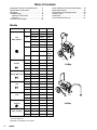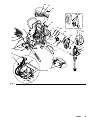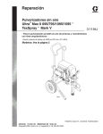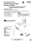
1
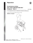
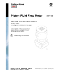
Repair
Ultrar Max II 695/795/1095/1595t
TexSprayt Mark V
Airless Sprayers
309941J
– For Portable Airless Spraying of Architectural Coatings and Paints –
3300 psi (227 bar, 22.7 MPa) Maximum Working Pressure
Models: See page 2
ti4281a
GRACO INC.ąP.O. BOX 1441ąMINNEAPOLIS, MNą55440-1441
Copyright 2004, Graco Inc. is registered to I.S. EN ISO 9001
Table of Contents
Component Function and Identification . . . . . 4
General Repair Information . . . . . . . . . . . . . . . 5
Grounding . . . . . . . . . . . . . . . . . . . . . . . . . . . . . . 5
Troubleshooting . . . . . . . . . . . . . . . . . . . . . . . . . 6
Mechanical/Fluid Flow . . . . . . . . . . . . . . . . 6
Electrical . . . . . . . . . . . . . . . . . . . . . . . . . . . . 7
Pressure Control Repair . . . . . . . . . . . . . . . . 10
Drive and Bearing Housing Replacement . .
Motor Replacement . . . . . . . . . . . . . . . . . . . . .
Displacement Pump Replacement . . . . . . . .
Technical Data . . . . . . . . . . . . . . . . . . . . . . . . .
Dimensions . . . . . . . . . . . . . . . . . . . . . . . . . . . .
Graco Standard Warranty . . . . . . . . . . . . . . .
Models
Vac
120
Model
Type
Lo-Boy
Hi-Boy
695
Standard
248037
248036
Premium
248031
248030
Standard
248308
248038
Premium
248033
248032
795
North America
1095
1595
R
Standard
248039
Premium
248034
Standard
248747
248040**
Premium
248746
248035**
Mark V
249029**
249030
ti4281a
240
695
248042
Europe
795
248043
1095
248044
Mark V
249031
248046
240
695
Europe Multi-cord
795
248047
1095
248048
Mark V*
249178
110
695
248049
UK
795
248050
1095
248051
Mark V
249072
248058
695
Asia
795
248059
1095
248060
248057
240
695
248593
248592
Australia
795
249431
248594
248595
100
695
248053
248052
Japan & Taiwan
795
248055
248054
1095
* Also for Asia and Australia;
Not ETL Approved
All models not available in all countries.
**
309941
Hi-Boy
248045
240
1095
2
248041
248056
ti4278a
Lo-Boy
16
18
20
21
21
22
WARNING
FIRE AND EXPLOSION HAZARD
Flammable fumes, such as solvent and paint fumes, in work area can ignite or explode. To help prevent fire and explosion:
D Use equipment only in well ventilated area.
D Eliminate all ignition sources; such as pilot lights, cigarettes, portable electric lamps, and plastic
drop cloths (potential static arc).
D Keep work area free of debris, including solvent, rags and gasoline.
D Do not plug or unplug power cords or turn lights on or off when flammable fumes are present.
D Ground equipment and conductive objects in work area. See Grounding instructions.
D Use only conductive hoses.
D Hold gun firmly to side of grounded pail when triggering into pail.
D If there is static sparking or you feel a shock, stop operation immediately. Do not use equipment
until you identify and correct the problem.
INJECTION HAZARD
High–pressure fluid from gun, hose leaks, or ruptured components will pierce skin. This may look like
just a cut, but it is a serious injury that can result in amputation. Get immediate medical attention.
D Do not point the gun at anyone or at any part of the body.
D Do not put your hand over the spray tip.
D Do not stop or deflect leaks with your hand, body, glove or rag.
D Do not spray without tip guard and trigger guard installed.
D Engage trigger lock when not spraying.
D Follow the Pressure Relief Procedure on page 5 if the spray tip clogs and before cleaning,
checking or servicing the equipment.
ELECTRIC SHOCK HAZARD
Improper grounding, setup or usage of the system can cause electric shock.
D Turn off and disconnect power cord before servicing equipment. Wait 5 minutes after disconnecting
from power source before servicing motor control.
D Use only grounded electrical outlets.
D Use only 3-wire extension cords.
D Ensure ground prongs are intact on sprayer and extension cords.
PERSONAL PROTECTIVE EQUIPMENT
You must wear appropriate protective equipment when operating, servicing, or when in the operating
area of the equipment to help protect you from serious injury, including eye injury, inhalation of toxic
fumes, burns, and hearing loss. This equipment includes but is not limited to:
D Protective eyewear
D Clothing and respirator as recommended by the fluid and solvent manufacturer
D Gloves
D Hearing protection
PRESSURIZED ALUMINUM PARTS HAZARD
Do not use 1,1,1–trichloroethane, methylene chloride, other halogenated hydrocarbon solvents or
fluids containing such solvents in pressurized aluminum equipment. Such use can cause serious
chemical reaction and equipment rupture, and result in death, serious injury, and property damage.
309941
3
Component Identification and Function
G
A
B
R
P
S
V
ti2377a
J
K
H
T
N
F
E
W
M
ti4281a
U
D
Fig. 1
4
A
Motor
DC motor, permanent magnet, totally enclosed, fan cooled
B
Drive Assembly
Transfers power from DC motor to displacement pump
D
Displacement Pump
Transfers fluid to be sprayed from source through spray gun
E
Fluid Outlet
Fluid hose is connected here
F
Prime Valve
Used to prime and drain sprayer (also relieves fluid outlet pressure) when open
G
Fluid Filter
Final filter of fluid to spray gun
H
Pressure Control Knob
Controls fluid outlet pressure
J
Pressure Control
Controls motor speed to maintain fluid outlet pressure at displacement pump
outlet. Works with pressure adjusting knob.
K
ON/OFF Switch
Power switch that controls main power to sprayer
M
50 ft (15 m) Main Hose
1/4 in. ID, grounded, nylon hose with spring guards on both ends
N
Spray Gun
High pressure spray gun with gun safety latch
P
Spray Tip
Uses high pressure fluid to clear tip clogs without removing tip from spray gun
R
HandTitet Tip Guard
Tip guard reduces risk of injection injury
S
Gun Safety Latch
Gun safety latch inhibits accidental triggering of spray gun. Contractor II gun
shown. Refer to your gun manual to properly set your gun safety latch.
T
Hose Rack
Holds wrapped hose for storage
U
Suction Tube
Transfers fluid to be sprayed from source to pump
V
Drain Tube
Fluid outlet used to drain and prime the sprayer
W
AutoClean
Reverse flush system
309941
General Repair Information
Pressure Relief Procedure
CAUTION
To reduce risk of pressure control malfunction:
WARNING
INJECTION HAZARD
System pressure must be manually
relieved to prevent system from starting
or spraying accidentally. Fluid under high
pressure can be injected through skin and cause
serious injury. To reduce risk of injury from injection, splashing fluid, or moving parts, follow Pressure Relief Procedure whenever you:
D
D
D
D
are instructed to relieve pressure,
stop spraying,
check or service any system equipment,
or install or clean spray tip.
D
Use needle nose pliers to disconnect wire. Never
pull on wire, pull on connector.
D
Mate wire connectors properly. Center flat blade of
insulated male connector in female connector.
D
Route wires carefully to avoid interference with
other connections of pressure control. Do not pinch
wires between cover and control box.
1. Keep all screws, nuts, washers, gaskets, and
electrical fittings removed during repair procedures. These parts are not normally provided with
replacement assemblies.
WARNING
ELECTRIC SHOCK HAZARD
MOVING PARTS HAZARD
HOT SURFACE HAZARD
To reduce risk of serious injury, including
electric shock, do not touch moving or
electrical parts with fingers or tools while
testing repair. Shut off and unplug sprayer when inspection is complete. Install all
covers, guards, gaskets, screws, washers and shroud before operating
sprayer.
1. Turn pressure control knob to zero.
2. Turn ON/OFF switch to OFF.
3. Unplug power supply cord.
4. Hold metal part of gun firmly to grounded metal
pail. Trigger gun to relieve pressure.
5. Lock gun safety latch.
6. Open prime valve. Leave prime valve open until
ready to spray again.
If suspected that spray tip or hose is completely
clogged, or that pressure has not been fully relieved
after following steps above, VERY SLOWLY loosen tip
guard retaining nut or hose end coupling to relieve
pressure gradually, then loosen completely. Now clear
tip or hose obstruction.
2. Test repair after problem is corrected.
3. If sprayer does not operate properly, review
repair procedure to verify procedure was done
correctly. If necessary, see Troubleshooting, pages
6 – 9, for other possible solutions.
Grounding
WARNING
Improper installation or alteration of grounding plug
results in risk of electric shock, fire or explosion
that could cause serious injury or death.
1. Fig. 2. Ultra Max II 695, 795 and 1095 100–120
Vac models require a 50/60 Hz, 15A circuit with a
grounding receptacle. Ultra Max II 1595 120 Vac
models require a 50/60 Hz 20A circuit with a
grounding receptacle; 220–240 Vac models require
a 50/60 Hz, 10A circuit with a grounding receptacle.
2. Do not alter ground prong or use adapter.
Grounding Plug
Grounded
Outlets
Fig. 2
3. 120 Vac: A 12 AWG, 3 wires with grounding prong,
300 ft (90 m) extension cord may be used.
220–240 Vac: You may use a 3-wire, 1.0 mm (12
AWG) (minimum) extension cord up to 90 m long.
Long lengths reduce sprayer performance.
309941
5
Troubleshooting
Relieve pressure; page 5.
Mechanical/Fluid Flow
TYPE OF PROBLEM
WHAT TO CHECK
If check is OK, go to next check
WHAT TO DO
When check is not OK refer to this column
Low or No Fluid/Pressure Output
1. Spray tip worn
1. Follow Pressure Relief Procedure Warning, then replace tip. See your separate
gun or tip manual.
2. Spray tip clogged
2. Relieve pressure. Check and clean spray
tip.
3. Paint supply
3. Refill and reprime pump
4. Intake strainer clogged
4. Remove and clean, then reinstall
5. Intake valve ball and piston ball are not seating 5. Remove intake valve and clean. Check
properly
balls and seats for nicks; replace if necessary, page 20. Strain paint before using to
remove particles that could clog pump.
6. Suction hose connections
6. Tighten any loose connections. Check for
missing or damaged seals.
7. Filter clogged
7. Relieve pressure. Check and clean filter.
8. Prime valve leaking
8. Relieve pressure. Repair prime valve.
9. Verify pump does not continue to stroke when 9. Service pump. See page 20.
gun trigger is released. (Prime valve not leaking.)
10. Leaking around throat packing nut which may 10.Replace packings, page 20. Also check
indicate worn or damaged packings. See page
piston valve seat for hardened paint or
20.
nicks and replace if necessary. Tighten
packing nut/wet-cup.
11. Pump rod damage
11. Repair pump, page 20
12.Low stall pressure
12. Do either or both:
a. Turn pressure control knob fully
clockwise. Make sure pressure
control knob is properly installed to
allow full clockwise position.
b.
Try a new pressure transducer.
Motor runs but pump does not 1. Displacement pump pin (32) damaged or miss- 1. Replace pump pin if missing. Be sure reing, page 20
tainer spring (31) is fully in groove all
stroke
around connecting rod, page 20.
6
309941
2. Connecting rod assembly (43) damaged,
page 16
2. Replace connecting rod assembly, page 16
3. Gears or drive housing damaged, page 16
3. Inspect drive housing assembly and gears
for damage and replace if necessary,
page 16
Troubleshooting
Electrical
Symptom: Sprayer does not run or stops running
D
Relieve pressure; page 5.
D Plug sprayer into correct voltage, grounded outlet
D Set power switch OFF for 30 seconds and then ON
again. This ensures sprayer is in normal run mode.
D Turn pressure control knob clockwise 1/2 turn.
D View digital display
WARNING
To avoid electrical shock or moving parts hazards
when covers are removed for troubleshooting, wait
30 seconds after unplugging power cord for stored
electricity to dissipate. Keep clear of electrical and
moving parts during troubleshooting procedures.
D If no digital display is available, use control board
status light to troubleshoot problems: Turn ON/OFF
switch OFF, remove control cover and then turn
power back ON. Observe status light.
CONTROL BOARD
STATUS LIGHT
INDICATION
WHAT TO DO
Blank
Never lights
No power to control
board
1. Verify required voltage is present
LED 100
DIGITAL
DISPLAY
2. Check wiring connections to control board
3. Perform continuity check on power cord and switch.
Replace power cord or switch as needed.
4. If steps 1 – 3 are ok, replace control board
–––– psi
Blinks once and
stops
No RUN command
to control board.
1. Make sure prime valve is open and there is no pressure in the system
2. Turn pressure control knob clockwise
3. Check potentiometer connection to control board
4. Check pressure control knob alignment to potentiometer shaft. Turn shaft fully clockwise and attach knob
in full ON position.
5. Unplug potentiometer. Short out center pin of control
board potentiometer connector to each outer pin (one
at a time). If sprayer runs, replace potentiometer,
page 15.
6. Check transducer connection
7. Disconnect and reconnect transducer plug to ensure
good connection with control board socket. Check
that transducer contacts are clean.
8. Open prime valve. Connect a known good transducer
in place of the sprayer transducer. Set sprayer ON.
Replace transducer If sprayer runs. Replace control
board If sprayer does not run.
309941
7
Troubleshooting
Electrical
DIGITAL
DISPLAY
Displays high
pressure
when prime
valve is open
and there is
no pressure in
sprayer.
CONTROL BOARD
STATUS LIGHT
–
Blinks 2 x repeatedly
E=02
INDICATION
Improper pressure
signal to control
Control board is receiving excessive
pressure signal
from transducer.
Transducer may be
damaged or fluid
flow path may be
clogged.
WHAT TO DO
Open prime valve. Connect a known good transducer in place of the sprayer transducer. Set
sprayer ON. Replace transducer If sprayer runs.
Replace control board If sprayer does not run.
1. Check fluid path for clogs, such as a clogged
filter.
2. Open prime valve and gun if running AutoClean
3. Use airless paint spray hose with no metal
braid, 1/4 in. x 50 ft minimum. Smaller hose or
metal braid hose may result in high-pressure
spikes.
4. Replace transducer if fluid path is not clogged
and proper hose is used
Blinks 3 x repeatedly
E=03
Transducer or
transducer connection error
1. Check transducer connection
2. Disconnect and reconnect transducer plug to
ensure good connection with control board
socket. Check that transducer contacts are ok.
3. Open prime valve. Connect a known good
transducer in place of the sprayer transducer.
Set sprayer ON. Replace transducer If sprayer
runs. Replace control board If sprayer does not
run.
8
309941
Troubleshooting
Electrical
DIGITAL
DISPLAY
CONTROL BOARD
STATUS LIGHT
INDICATION
WHAT TO DO
E=05
Blinks 5 x repeatedly
Possible locked
pump or drive. May
be motor connection
or wiring error.
1. Check motor wiring connections
2. Check for locked or frozen pump or drive train
3. If all motor wiring connections are OK and pump/
drive train are not locked up, replace motor
E=06
E=07
Blinks 6 x repeatedly
Blinks 7 x repeatedly
Motor is too hot or
motor/thermal device connection may
be bad.
Exceeded 2000 psi
during timed flush
cycle
1. Check all wire connections from motor to control
board
2. If connections are all ok, allow sprayer to cool. If
sprayer runs when cool, correct cause of overheating. Keep sprayer in cooler location with good
ventilation. Make sure motor air intake is not
blocked.
This error only occurs in flush timer mode
1. Make sure prime valve and gun are open
2. Make sure no flow obstructions or clogged filter
E=09
Blinks 9 x repeatedly
Motor sensor failure
E=10
Blinks 10 x repeatedly
High control board
temperature
Make sure motor sensor (resolver) is connected to
the control board and check wiring for damage
1. Make sure the motor air intake is not blocked
2. Make sure control board is properly connected to
the back plate and that conductive thermal paste
is used on the power components, Fig. 3
E=11
Blinks 11 x repeatedly
Excessive motor
speed
E=12
Blinks 12 x repeatedly
High Current
Check for damaged gears or disconnected pump
1. Check for locked or frozen pump or drive train
2. Check for possible short circuits in wiring
3. Check pressure output and replace transducer if
pressure is excessive
E=13
EMPTY
Blinks 13 x repeatedly
–
Model not selected
Control board identity resistors must be properly
clipped to identify model type, manual 310657
EMPTY on digital
display indicates a
loss of paint to the
pump or a severe
loss in pressure
1. Check for empty paint condition, clogged inlet
strainer, failed pump or severe leak. Turn pressure
control knob to zero to restart sprayer.
2. WatchDog (W-DOG) feature can be deactivated.
See Operation Manual 309935.
309941
9
Pressure Control Repair
100 – 120 Vac North American and Japan/Taiwan Motor Control Board
Removal
Installation
1. Fig. 3. Apply small amount of thermal compound
110009 (5) to shaded component areas on rear of
motor control board (95).
Relieve pressure; page 5.
Wait 5 minutes before servicing.
1.
CAUTION
2. Fig. 3. Remove four screws (38) and cover (96).
3. Disconnect display connector (A) from motor
control board (95).
To reduce risk of motor control board failure, do not
overtighten screws (102) which can damage the
electric components.
4. Remove bottom two screws (39) and allow control
panel (68) to hang down freely.
2. Install motor control board (95) with five screws
(27). Torque to 9–11 in-lb (1.02 – 1.24 N·m). Install
and torque three screws (102) to values in Fig 3.
3. Connect motor connectors (F, G and H) to motor
control board.
4. Install control box (61) with top two screws (39).
5. Connect transducer connector (E) to motor control
board.
6. Connect 15/20A switch (178) (1595).
7. Connect motor control board power lead(s) (D) to
ON/OFF switch (33).
8. Connect potentiometer connector (C) to motor
control board.
9. Install control panel (68) with two screws (39) .
10. Connect display connector (A) to motor control
board.
11. Install cover (96) with four screws (38).
5. Disconnect control board power lead(s) (D) from
ON/OFF switch (33) and motor control board (95).
6. Disconnect potentiometer connector (C) from
motor control board.
7. Disconnect 15/20A switch (178) (1595).
8. Disconnect transducer connector (E) from motor
control board.
9. Disconnect motor connectors (F, G and H) from
motor control board.
10. Remove top two screws (39) and control box (61).
11. Remove five screws (27), three screws (102) and
motor control board.
5
100 – 120 Vac
North American
and Japan/Taiwan
Tighten 1 screw
to 14–17 in–lb
95
26
61
A
F
C
G
A
96
95
27
40
38
33 D
Tighten 2 screws
to 7–10 in–lb
E
39
80
C
1 178
68
Fig. 3
309941
39
115
34
ti4289b
20
67
82
10
B
H
102
E
1 1595
240 Vac Motor Control Board
Removal
1.
Relieve pressure; page 5.
Wait 5 minutes before servicing.
Installation
1. Fig. 4. Apply small amount of thermal compound
110009 (5) to shaded areas on rear of motor
control board (95).
2. Fig. 4. Remove four screws (38) and cover (96).
3. Disconnect display connector (A) from motor
control board (95).
4. Remove bottom two screws (39). Disconnect
potentiometer connector (C) from motor control
board (95). Disconnect power cord connectors (D)
and filter board connectors (J) from ON/OFF
switch (33) and remove control panel (68).
5. Disconnect motor control board power connectors
(K) from filter board (146).
6. Remove top two screws (39) and control box (61).
7. Disconnect transducer connector (E) from motor
control board.
8. Disconnect motor connectors (F, G and H) from
motor control board.
9. Remove five screws (27), three screws (102) and
motor control board.
CAUTION
To reduce risk of motor control board failure, do not
overtighten screws (102) which can damage the
electric components.
2. Install motor control board (95) with five screws
(27). Torque to 9–11 in-lb (1.02 – 1.24 N·m). Install
and torque three screws (102) to values shown in
Fig 5.
3. Connect motor connectors (F, G and H) to motor
control board.
4. Connect transducer connector (E) to motor control
board.
5. Connect motor control board power connectors (K)
to filter board (146).
6. Install control box (61) with top two screws (39).
7. Connect filter board power connectors (J) and power
cord connectors (D) to ON/OFF switch (33).
8. Connect potentiometer connector (C) to motor
control board.
9. Install control panel (68) with two screws (39) .
10. Connect display connector (A) to motor control
board (95).
11. Install cover (96) with four screws (38).
240 Vac Filter Board
Removal
1.
Relieve pressure; page 5.
Wait 5 minutes before servicing.
2. Fig. 4. Remove four screws (38) and cover (96).
3. Disconnect display connector (A) from motor
control board (95).
4. Remove bottom two screws (39). Disconnect
potentiometer connector (C) from motor control
board (95). Disconnect power cord connectors (D)
and filter board connectors (J) from ON/OFF
switch (33) and remove control panel (68).
Installation
1. Fig. 4. Install filter board (146) with four screws
(163).
2. Connect motor control board power connectors (K)
to filter board (146).
3. Connect filter board power connectors (J) to top
two terminals of ON/OFF switch (33) and power
cord connectors (D) to bottom two terminals of
ON/OFF switch.
4. Connect potentiometer connector (C) to motor
control board (95).
5. Install control panel (68) with two screws (39).
5. Disconnect motor control board power connectors
(K) from filter board (146).
6. Connect display connector (A) to motor control
board (95).
6. Remove four screws (163) from filter board (146).
7. Install cover (96) with four screws (38).
309941
11
5
240 Vac
95
Tighten 1 screw
to 14–17 in-lb (1.58–1.92 NSm)
26
K
61
146
163
A
F
C
G
A
96
B
H
102
E
95
38
33
J
A
27
A
Tighten 2 screws
7–10 in–lb (.79–1.13 NSm)
39
D
E
C
80
ti4345a
20
68
39
67
82
34
Fig. 4
12
309941
115
110 Vac U.K. Motor Control Board
Removal
1.
Relieve pressure; page 5.
Wait 5 minutes before servicing.
Installation
1. Fig. 5. Apply small amount of thermal compound
110009 (5) to shaded areas on rear of motor
control board (95).
2. Fig. 5. Remove four screws (38) and cover (96).
3. Disconnect display connector (A) from motor
control board (95).
4. Remove bottom two screws (39). Disconnect
potentiometer connector (C) from motor control
board (95). Disconnect filter board connector (J)
and power cord connector (D) from ON/OFF
switch (33). Remove control panel (68).
5. Disconnect motor control board power connectors
(K) from filter board (146). Disconnect filter connector (L) from power cord connector (L).
6. Remove top two screws (39) and control box (61).
7. Disconnect transducer connector (E) from motor
control board.
8. Disconnect motor connectors (F, G and H) from
motor control board.
9. Remove five screws (27), three screws (102) and
motor control board.
CAUTION
To reduce risk of motor control board failure, do not
overtighten screws (102) which can damage the
electric components.
2. Install motor control board (95) with five screws
(27). Torque to 9–11 in-lb (1.02 – 1.24 N·m). Install
and torque three screws (102) to values shown in
Fig 5.
3. Connect motor connectors (F, G and H) to motor
control board.
4. Connect transducer connector (E) to motor control
board.
5. Connect motor control board power connectors (K)
to filter board (146). Connect filter connector (L) to
power cord connector (L).
6. Install control box (61) with top two screws (39).
7. Fig. 5. Connect filter board power connector (J)
and power cord connector (D) to ON/OFF
switch (33).
8. Connect potentiometer connector (C) to motor
control board.
9. Install control panel (68) with two screws (39) .
10. Connect display connector (A) to motor control
board (95).
11. Install cover (96) with four screws (38).
110 Vac U.K. Filter Board
Removal
1.
Relieve pressure; page 5.
Wait 5 minutes before servicing.
Installation
1. Fig. 5. Connect motor control board power connectors (K) to filter board (146). Connect filter connector (L) to power cord connector (L).
2. Fig. 5. Remove four screws (38) and cover (96).
2. Install filter board (146) with four screws (163).
3. Disconnect display connector (A) from motor
control board (95).
3. Fig. 5. Connect filter board power connector (J)
and power cord connector (D) to ON/OFF
switch (33).
4. Remove bottom two screws (39). Disconnect
potentiometer connector (C) from motor control
board (95). Disconnect filter board connector (J)
and power cord connector (D) from ON/OFF
switch (33). Remove control panel (68).
4. Connect potentiometer connector (C) to motor
control board (95).
5. Install control panel (68) with two screws (39).
5. Disconnect motor control board power connectors
(K) from filter board (146). Disconnect filter connector (L) from power cord connector (L).
6. Connect display connector (A) to motor control
board (95).
6. Remove four screws (163) from filter board (146).
7. Install cover (96) with four screws (38).
309941
13
5
110 Vac U.K.
95
Tighten 1 screw
to 14–17 in lb (1.58–1.92 NSm)
26
K
61
146
163
A
F
C
G
A
96
B
H
102
E
95
38
33
J
A
27
A
L
Tighten 2 screws
7–10 in–lb (.79–1.13 NSm)
39
D
E
C
80
ti5015a
20
68
39
67
82
34
Fig. 5
14
309941
115
Pressure Adjust Potentiometer
Removal
1.
Installation
Relieve pressure; page 5.
Wait 5 minutes before servicing.
2. Fig. 3, 4 or 5. Remove four screws (38) and
cover (96).
3. Disconnect potentiometer connector (C) from
motor control board (95).
4. Remove pressure control knob (34) with a hex
wrench.
5. Remove gasket (115), nut and potentiometer (82)
from control panel (68).
1. Install gasket (115), nut and potentiometer (82) on
control panel (68). Torque nut to 30–35 in-lb
(3.38–3.95 N·m).
2. Install pressure control knob (34): Check pressure
control knob alignment to potentiometer shaft.
Turn shaft fully clockwise and attach knob in full
ON position with a hex wrench.
3. Connect potentiometer connector (C) to motor
control board.
4. Install cover (96) with four screws (38).
Pressure Control Transducer
Removal
1.
7. Remove grommet (40) from transducer and save
for reuse.
Relieve pressure; page 5.
Wait 5 minutes before servicing.
2. Fig. 3 or 5. Remove four screws (38) and
cover (96).
3. Disconnect transducer connector (E) from motor
control board (95).
4. Disconnect potentiometer connector (C) from
motor control board.
5. Remove four screws (39) and control box (61).
Allow control panel to hang down freely.
6. Remove transducer (86) and o-ring (20) from filter
base (67).
Installation
1. Install o-ring (20) and transducer (86) in filter base
(67). Torque to 35–45 ft-lb (47–61 N·m).
2. Install grommet (40) onto transducer (86).
3. Connect transducer connector (E) to motor control
board.
4. Install control box (61) and control panel (68) with
four screws (39).
5. Connect potentiometer connector (C) to motor
control board.
6. Install cover (96) with four screws (38).
309941
15
Drive and Bearing Housing Replacement
CAUTION
Do not drop gear cluster (89) when removing drive
housing (90). Gear cluster may stay engaged in
motor front end bell or drive housing.
Disassembly
1.
Relieve pressure; page 5.
2. Remove screw (31), two nuts (24), pail hanger (55)
and pump rod cover (108).
7. Remove five screws (6) and pull drive housing (90)
off motor (84).
Assembly
Fig. 7. Make sure gear (89) and thrust washers (28,
30, 90a, 36) are in place. Brush grease onto gear
teeth.
1. Fig. 6. Push drive housing (90) onto motor (84)
and install with five screws (6). Torque to 190–210
in-lb (21–23 N·m).
2. Install bearing housing (83) with four screws (14)
and washers (12). Torque to 25–30 ft-lb (34–40
N·m).
3. Remove pump (91); Displacement Pump Re3. Install front cover (51) with four screws (31).
placement, page 20.
4. Install shroud (72) with two screws (31).
4. Fig. 6. Remove two screws (158) and shroud (72).
5. Install pump (41); Displacement Pump Replace5. Remove four screws (158) and front cover (51).
6. Remove four screws (14) and washers (12) to
remove bearing housing (83) and connecting
rod (85).
16
309941
ment, page 20.
6. Install pump rod cover (108) and pail hanger (55)
with screw (31) and two nuts (24).
157
72
84
158
90
51
158
6
157
ti4253a
85
24
44
43
12
14
31
55
56
Fig. 6
108
309941
17
Motor Replacement
Removal
Installation
Relieve pressure; page 5.
Wait 5 minutes before servicing.
1.
1. Slide new motor (84) under two screws (23) in cart
frame (62) near control.
2. Remove pump (91); Displacement Pump Replacement, page 20.
CAUTION
Do not drop gear cluster (89) when removing drive
housing (90). Gear cluster may stay engaged in
motor front end bell or drive housing.
2. Install two screws (23) and nuts (19) on motor side
opposite control.
3. Tighten all four screws (23) and nuts (19). Torque
nuts to 115–135 in-lb (13–15 N·m).
4. Install strain relief (29) onto motor wires and into
power bar plate (69).
3. Remove drive housing (89); Drive Housing Replacement, page 16.
4. Fig. 7. Remove four screws (38) and control cover
(96).
5. Install control housing (61) with top two
screws (39).
5. Remove bottom two screws (39) and and allow
control panel (68) to hang down freely.
6. Connect all three motor connectors to motor
control board (95).
6. Disconnect all three motor connectors from motor
control board (95).
7. Install control panel (68) with two screws (39).
7. Remove top two screws (39) and control
housing (61).
8. Install control cover (96) with four screws (38).
8. Remove strain relief (29) from motor wires and
power bar plate (69).
9. Remove two screws (23) and nuts (19) on side
opposite control.
10. Loosen two nuts (19) on side near control and
remove motor (84) from cart frame (62).
18
309941
9. Install drive housing (42); Drive Housing Replacement, page 16.
10. Install pump (13); Displacement Pump Replacement, page 20.
158
157
58
(A) 795
23
84
36
19
61
90A
51 157
158
28
90
96
38
89
30
6
12
68
14
39
31
ti4254a
29
27
69
23
19
LED Status Light
95
Fig. 7
309941
19
Displacement Pump Replacement
See manual 310643 for pump repair instructions.
See manual 309943, 309944 or 309951 – 309954 for
applicable sprayer part number references.
Removal
1. Flush pump (13).
2.
4. Fig. 10. Cycle pump in JOG mode until pump pin
(44) is in position to be removed. Turn power
switch OFF and unplug power cord. Push up
retaining ring (43) and push pump pin out.
Relieve pressure; page 5.
5. Fig. 9. Remove suction tube (76), hose (94) and
any washers and o-rings.
3. Fig. 8. Remove screw (31) and slide pump rod
shield (108) forward.
6. Loosen pump jam nut (56). Unscrew pump.
94
ti4258a
56
76
108
Fig. 8
31
ti4258a
Fig. 9
Installation
4. Screw in pump until threads are flush with drive
housing opening. Align pump outlet to back.
WARNING
If pump pin works loose, parts could break off due
to force of pumping action. Parts could project
through the air and result in serious injury or property damage.
CAUTION
5. Fig. 9. Install washers, o-rings and suction tube
(76) and hose (94).
6. Fig. 11. Screw jam nut (56) up onto pump until nut
stops. Tighten jam nut by hand, then tap 1/8 to 1/4
turn with a 20 oz (maximum) hammer to approximately 75" 5 ft–lb (102 Nm).
If the pump jam nut loosens during operation, the
threads of the drive housing will be damaged.
1. Fig. 10. Extend pump piston rod 1.5 in. Apply
grease to top of pump rod at (A) or inside connecting rod.
Fig. 11
44
1.5 in.
7. Fig. 8. Install pump rod shield (108) with screw
(31).
A
8. Fig. 12. Fill packing nut with Graco TSL until fluid
flows onto top of seal.
43
Fig. 10
ti4258a
2. Install pump pin (44). Verify retaining spring (43) is
in groove of connecting rod (85).
3. Push pump up until pump threads engage.
20
309941
ti4258a
Fig. 12
Technical Data
Model
100–120V, 220–240V, Generator Motor HP (W)
A, Hz
∅, A, Hz
Minimum
W
Cycles per
gallon (liter)
Maximum
Delivery gpm
(lpm)
Maximum
Tip size
Fluid Outlet
npsm
1 Gun
2 Guns
695
14, 50/60
9, 50/60
5000
1.75 (1300)
243 (64)
0.75 (2.8)
0.027
N/A
1/4 in.
795
15, 50/60
10, 50/60
5000
2.00 (1490)
195 (52)
0.95 (3.6)
0.031
0.021
1/4 in
1095
15, 50/60
10, 50/60
5000
2.20 (1640)
123 (33)
1.1 (4.1)
0.033
0.023
1/4 in
Mark V
N/A
10, 50/60
5000
2.20 (1640)
110 (29)
1.2 (4.3)
0.035
0.023
3/8 in
1595
20/15,
50/60
N/A
5000
2.5 (1860)
110 (29)
1.25 (4.7)
0.037
0.025
1/4 in
Mark V
20/15,
50/60
N/A
5000
2.5 (1860)
110 (29)
1.25 (4.7)
0.037
0.025
3/8 in
Basic Sprayer Wetted Parts: . . . . . . . . . . . . . . . . . . . . . . . . . . . .
zinc- and nickel-plated carbon steel, nylon, stainless
steel, PTFE, Acetel, leather, UHMWPE, aluminum,
tungsten carbide, PEEK, brass
Noise Level
Sound power . . . . . . . . . . . . . . . . . . . . . . . . . 91 dBa*
Sound pressure . . . . . . . . . . . . . . . . . . . . . . . 82 dBa*
* per ISO 3744; measured at 3.1 feet (1 m)
Dimensions
Model
Weight lb (kg)
Lo-Boy
Height in. (cm)
Hi-boy
Lo-Boy
Hi-Boy
Length
in. (cm)
in
Width
in. (cm)
in
695
94 (43)
94 (43)
26.5 (67.3) Handle down,
38.8 (98.6) Handle up
28.5 (72.4) Handle down,
38.75 (98.4) Handle up
25.75
(65.4)
20.5
(52.1)
795
98 (45)
98 (45)
26.5 (67.3) Handle down,
38.8 (98.6) Handle up
28.5 (72.4) Handle down,
38.75 (98.4) Handle up
25
(63.5)
20.5
(52.1)
1095
N/A
120 (55)
N/A
29.5 (74.9) Handle down,
38.5 (97.8) Handle up
26 (66)
22.5
(57.2)
1595
N/A
125 (57)
N/A
29.5 (74.9) Handle down,
38.5 (97.8) Handle up
26 (66)
22.5
(57.2)
Mark V
N/A
130 (59)
N/A
29.5 (74.9) Handle down,
38.5 (97.8) Handle up
26 (66)
22.5
(57.2)
309941
21
Graco Standard Warranty
Graco warrants all equipment referenced in this document which is manufactured by Graco and bearing its name to be free from
defects in material and workmanship on the date of sale by an authorized Graco distributor to the original purchaser for use. With the
exception of any special, extended, or limited warranty published by Graco, Graco will, for a period of twelve months from the date of
sale, repair or replace any part of the equipment determined by Graco to be defective. This warranty applies only when the equipment
is installed, operated and maintained in accordance with Graco’s written recommendations.
This warranty does not cover, and Graco shall not be liable for general wear and tear, or any malfunction, damage or wear caused by
faulty installation, misapplication, abrasion, corrosion, inadequate or improper maintenance, negligence, accident, tampering, or substitution of non–Graco component parts. Nor shall Graco be liable for malfunction, damage or wear caused by the incompatibility of
Graco equipment with structures, accessories, equipment or materials not supplied by Graco, or the improper design, manufacture,
installation, operation or maintenance of structures, accessories, equipment or materials not supplied by Graco.
This warranty is conditioned upon the prepaid return of the equipment claimed to be defective to an authorized Graco distributor for
verification of the claimed defect. If the claimed defect is verified, Graco will repair or replace free of charge any defective parts. The
equipment will be returned to the original purchaser transportation prepaid. If inspection of the equipment does not disclose any defect
in material or workmanship, repairs will be made at a reasonable charge, which charges may include the costs of parts, labor, and
transportation.
THIS WARRANTY IS EXCLUSIVE, AND IS IN LIEU OF ANY OTHER WARRANTIES, EXPRESS OR IMPLIED, INCLUDING BUT
NOT LIMITED TO WARRANTY OF MERCHANTABILITY OR WARRANTY OF FITNESS FOR A PARTICULAR PURPOSE.
Graco’s sole obligation and buyer’s sole remedy for any breach of warranty shall be as set forth above. The buyer agrees that no other
remedy (including, but not limited to, incidental or consequential damages for lost profits, lost sales, injury to person or property, or any
other incidental or consequential loss) shall be available. Any action for breach of warranty must be brought within two (2) years of the
date of sale.
GRACO MAKES NO WARRANTY, AND DISCLAIMS ALL IMPLIED WARRANTIES OF MERCHANTABILITY AND FITNESS FOR
A PARTICULAR PURPOSE, IN CONNECTION WITH ACCESSORIES, EQUIPMENT, MATERIALS OR COMPONENTS SOLD
BUT NOT MANUFACTURED BY GRACO. These items sold, but not manufactured by Graco (such as electric motors, switches,
hose, etc.), are subject to the warranty, if any, of their manufacturer. Graco will provide purchaser with reasonable assistance in making any claim for breach of these warranties.
In no event will Graco be liable for indirect, incidental, special or consequential damages resulting from Graco supplying equipment
hereunder, or the furnishing, performance, or use of any products or other goods sold hereto, whether due to a breach of contract,
breach of warranty, the negligence of Graco, or otherwise.
FOR GRACO CANADA CUSTOMERS
The parties acknowledge that they have required that the present document, as well as all documents, notices and legal proceedings
entered into, given or instituted pursuant hereto or relating directly or indirectly hereto, be drawn up in English. Les parties reconnaissent avoir convenu que la rédaction du présente document sera en Anglais, ainsi que tous documents, avis et procédures judiciaires
exécutés, donnés ou intentés à la suite de ou en rapport, directement ou indirectement, avec les procedures concernées.
TO PLACE AN ORDER OR FOR SERVICE, contact your Graco distributor, or call 1–800–690–2894 to identify the
nearest distributor.
All written and visual data contained in this document reflects the latest product information available at the time of publication. Graco reserves the
right to make changes at any time without notice.
This manual contains English GN 309941 MM 309941
Graco Headquarters: Minneapolis
International Offices: Belgium, China, Japan, Korea
GRACO INC. P.O. BOX 1441 MINNEAPOLIS, MN 55440–1441
www.graco.com
PRINTED IN USA 309941J
12/2003, Rev. 4/2005
22
309941