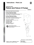
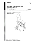
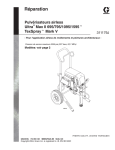
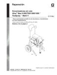
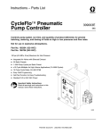
1
Parts
Instructions
7 in. (178 mm) DIAMETER
BulldogR Air Motor
307049V
100 psi (0.7 MPa, 7 bar) Maximum Air Input Pressure
Read warnings and instructions.
Model 208356, Series J
Standard Air Motor for most BulldogR Pumps
Model 625794, Series A
For BulldogR Sanitary Pumps
Model 208357, Series J
For BulldogR transfer pumps
Model 902098, Series A
For VRHM pumps
03330
Model 208356 Shown
GRACO INC.ąP.O. BOX 1441ąMINNEAPOLIS, MNą55440-1441
Copyright 2001, Graco Inc. is registered to I.S. EN ISO 9001
Table of Contents
Warnings . . . . . . . . . . . . . . . . . . . . . . . . . . . . . . . . . . . . . . 2
Installation . . . . . . . . . . . . . . . . . . . . . . . . . . . . . . . . . . . . . 5
Operation . . . . . . . . . . . . . . . . . . . . . . . . . . . . . . . . . . . . . 6
Troubleshooting . . . . . . . . . . . . . . . . . . . . . . . . . . . . . . . . 7
Service . . . . . . . . . . . . . . . . . . . . . . . . . . . . . . . . . . . . . . . 8
Parts
Model 208356, 902098 . . . . . . . . . . . . . . . . . . . . . . 20
Model 208357 . . . . . . . . . . . . . . . . . . . . . . . . . . . . . . 22
Model 625794 . . . . . . . . . . . . . . . . . . . . . . . . . . . . . . 24
Technical Data . . . . . . . . . . . . . . . . . . . . . . . . . . . . . . . .
Dimensions . . . . . . . . . . . . . . . . . . . . . . . . . . . . . . . . . . .
Mounting Hole Layout . . . . . . . . . . . . . . . . . . . . . . . . . .
Warranty . . . . . . . . . . . . . . . . . . . . . . . . . . . . . . . . . . . . .
Graco Phone Number . . . . . . . . . . . . . . . . . . . . . . . . . .
26
27
27
28
28
Symbols
Warning Symbol
Caution Symbol
WARNING
CAUTION
This symbol alerts you to the possibility of serious
injury or death if you do not follow the instructions.
This symbol alerts you to the possibility of damage to
or destruction of equipment if you do not follow the
instructions.
WARNING
EQUIPMENT MISUSE HAZARD
Equipment misuse can cause the equipment to rupture or malfunction and result in serious injury.
INSTRUCTIONS
D This equipment is for professional use only.
D Read all instruction manuals, tags, and labels before operating the equipment.
D Use the equipment only for its intended purpose. If you are uncertain about usage, call your Graco
distributor.
D Do not alter or modify this equipment. Use only genuine Graco parts and accessories.
D Check equipment daily. Repair or replace worn or damaged parts immediately.
D Do not exceed the maximum working pressure stated on the equipment or in the Technical Data
for your equipment. Do not exceed the maximum working pressure of the lowest rated component
in your system.
D Use fluids and solvents which are compatible with the equipment wetted parts. Refer to the Technical Data section of all equipment manuals. Read the fluid and solvent manufacturer’s warnings.
D Do not use hoses to pull equipment.
D Route hoses away from traffic areas, sharp edges, moving parts, and hot surfaces. Do not expose
Graco hoses to temperatures above 180_F (82_C) or below –40_F (–40_C).
D Wear hearing protection when operating this equipment.
D Do not lift pressurized equipment.
D Do not lift the equipment by the air motor lift ring if the total weight of the equipment exceeds 550 lb
(250 kg).
D Comply with all applicable local, state, and national fire, electrical, and safety regulations.
2
307049
WARNING
INJECTION HAZARD
Spray from the gun, hose leaks, or ruptured components can inject fluid into your body and cause
extremely serious injury, including the need for amputation. Fluid splashed in the eyes or on the skin
can also cause serious injury.
D Fluid injected into the skin might look like just a cut, but it is a serious injury. Get immediate medical attention.
D Do not point the gun at anyone or at any part of the body.
D Do not put your hand or fingers over the spray tip.
D Do not stop or deflect leaks with your hand, body, glove or rag.
D Do not “blow back” fluid; this is not an air spray system.
D Always have the tip guard and the trigger guard on the gun when spraying.
D Check the gun diffuser operation weekly. Refer to the gun manual.
D Be sure the gun trigger safety operates before spraying.
D Lock the gun trigger safety when you stop spraying.
D Follow the Pressure Relief Procedure on page 6 whenever you: are instructed to relieve pressure; stop spraying; clean, check, or service the equipment; and install or clean the spray tip.
D Tighten all fluid connections before operating the equipment.
D Check the hoses, tubes, and couplings daily. Replace worn, damaged, or loose parts immediately.
Permanently coupled hoses cannot be repaired; replace the entire hose.
D Use only Graco approved hoses. Do not remove any spring guard that is used to help protect the
hose from rupture caused by kinks or bends near the couplings.
MOVING PARTS HAZARD
Moving parts, such as the air motor piston, can pinch or amputate your fingers.
D Keep clear of all moving parts when starting or operating the pump.
D Before servicing the equipment, follow the Pressure Relief Procedure on page 6 to prevent the
equipment from starting unexpectedly.
307049
3
WARNING
FIRE AND EXPLOSION HAZARD
Improper grounding, poor ventilation, open flames or sparks can cause a hazardous condition and
result in a fire or explosion and serious injury.
D Ground the equipment and the object being sprayed. Refer to Grounding on page 5.
D If there is any static sparking or you feel an electric shock while using this equipment, stop spraying immediately. Do not use the equipment until you identify and correct the problem.
D Provide fresh air ventilation to avoid the buildup of flammable fumes from solvents or the fluid
being sprayed.
D Keep the spray area free of debris, including solvent, rags, and gasoline.
D Electrically disconnect all equipment in the spray area.
D Extinguish all open flames or pilot lights in the spray area.
D Do not smoke in the spray area.
D Do not turn on or off any light switch in the spray area while operating or if fumes are present.
D Do not operate a gasoline engine in the spray area.
TOXIC FLUID HAZARD
Hazardous fluid or toxic fumes can cause serious injury or death if splashed in the eyes or on the skin,
inhaled, or swallowed.
D Know the specific hazards of the fluid you are using.
D Store hazardous fluid in an approved container. Dispose of hazardous fluid according to all local,
state and national guidelines.
D Always wear protective eyewear, gloves, clothing and respirator as recommended by the fluid and
solvent manufacturer.
4
307049
Installation
General Information
6. Fluid supply container: follow your local code.
NOTE: Reference numbers and letters in parentheses
in the text refer to the callouts in the figures and the
parts drawing.
7. Solvent pails used when flushing: follow your local
code. Use only metal pails, which are conductive,
placed on a grounded surface. Do not place the
pail on a nonconductive surface, such as paper or
cardboard, which interrupts the grounding continuity.
NOTE: Always use Genuine Graco Parts and Accessories, available from your Graco distributor.
Grounding
WARNING
8. To maintain grounding continuity when flushing or
relieving pressure, hold a metal part of the spray
gun firmly to the side of a grounded metal pail,
then trigger the gun.
FIRE AND EXPLOSION HAZARD
Before operating the pump, ground the
system as explained below. Also read
the section FIRE AND EXPLOSION
HAZARD on page 4.
W
X
Y
Z
1. Pump: use a ground wire and clamp as shown in
Fig. 1. Loosen the grounding lug locknut (W) and
washer (X). Insert one end of a 12 ga (1.5 mm@)
minimum ground wire (Y) into the slot in lug (Z)
and tighten the locknut securely. Connect the other
end of the wire to a true earth ground. Order Part
No. 237569 Grounding Clamp and Wire.
2. Air and fluid hoses: use only electrically conductive
hoses with a maximum of 500 feet (150 m) combined hose length to ensure grounding continuity.
Check the electrical resistance of your air and fluid
hoses at least once a week. If the total resistance
to ground exceeds 29 megohms, replace the hose
immediately.
NOTE: Use a meter that is capable of measuring
resistance at this level.
3. Air compressor: follow manufacturer’s recommendations.
4. Spray gun or dispensing valve: ground through
connection to a properly grounded fluid hose and
pump.
5. Object being sprayed: follow your local code.
0864
Fig. 1
Air Motor Icing
Moisture in the compressed air can collect in the air
motor and freeze, causing the motor to stall. This is
called icing. If icing occurs, shut off the air supply and
allow the ice to thaw.
To minimize icing, reduce the moisture in your compressed air supply by using an air dryer or a filter
which traps water.
The main air line should slope slightly downward so
water will collect at the end of the line, where it can be
drained. Additionally, plumb a drop line from the top of
each main air line. Install an automatic drain or a drain
valve at the bottom of each drop.
For additional help in designing your system, contact
your Graco distributor.
307049
5
Operation
Pressure Relief Procedure
WARNING
INJECTION HAZARD
To reduce the risk of serious injury, including fluid injection, splashing in the
eyes or on the skin, or moving parts,
always follow the Pressure Relief Procedure
whenever you:
D
D
D
D
D
are instructed to relieve the pressure,
shut off the pump
stop spraying/dispensing,
check or service any of the system equipment,
or install or clean the spray tips/nozzle.
4. Unlock the gun/valve trigger safety. Hold a metal
part of the gun/valve firmly to a grounded metal
pail. Trigger the gun/valve to relieve pressure.
5. Lock the gun/valve trigger safety.
6. Open the fluid drain valve. Leave the fluid drain
valve open until you are ready to spray/dispense
again.
If you suspect that the spray tip/nozzle or hose is
completely clogged, or that pressure has not been fully
relieved after following the steps above, very slowly
loosen the tip guard retaining nut or hose end coupling
to relieve pressure gradually, then loosen completely.
Now clear the tip/nozzle or hose obstruction.
Preventive Maintenance Schedule
1. Lock the gun/valve trigger safety.
2. Turn off the air to the motor.
3. Close the bleed-type master air valve (required in
your system).
6
307049
The operating conditions of your particular system
determine how often maintenance is required. Establish a preventive maintenance schedule by recording
when and what kind of maintenance is needed, and
then determine a regular schedule for checking your
system.
Troubleshooting
Stalled Motor
WARNING
Moving parts can pinch or amputate your fingers or
other body parts. To reduce the risk of serious
injury, including amputation, keep fingers out of the
detent housing (45) and exhaust openings.
To restart a stalled motor, remove the lift ring (18) from
the detent housing (45) and use a screwdriver to push
the air valve housing (30) down. See Fig. 2.
Locating Air Leaks
To locate an air leak, shut off the air supply and disconnect the air hose. Screw the inlet union (3) out of
the air manifold (41). Remove the shield (51), then
screw the union back into the manifold. Connect the air
hose and turn the air on. Do not exceed 40 psi (0.28
MPa, 2.8 bar) incoming air pressure. Use the checking
methods listed below in the Check Chart to find where
the air is leaking. Refer to Fig. 2.
Detail of Air Director Valves
H (37, 17)
41
30
A or D (38)
Check Chart
06466
Stroke
Position
Model 208356 Shown
UP only
(air valve
housing
down)
18
45
Fig.
Ref.
Points
Checking
Method
Cause of
Leakage
A
By feel
Blown air
manifold
gaskets (38)
B
By feel
Blown air
cylinder
gasket (19)
C
Squirt oil
Worn throat
around wiper packings
seal (25)
(23 or 61)
D
By feel
Blown air
manifold
gasket (38)
E
By Feel
Damaged
wiper seal
(25)
F
Squirt oil
around
bearing (1)
Worn trip
rod packing
(21)
G
Squirt oil
around
bearing (1)
Damaged
trip rod
bearing
gasket (16)
H
Squirt oil
around air
valve (30)
Worn air
valves (37)
or o-rings
(17)
J
Hold paper
strip over
exhaust
holes
Worn piston
o-ring (29)
3
1
(16) G
DOWN only
(air valve
housing up)
F (21)
J (29)
(19) B
C
(23, 61)
E (25)
Fig. 2
06465
BOTH
307049
7
Service
WARNING
To avoid serious injury and equipment
damage, do not lift the equipment by the
air motor lift ring if the total weight of the
equipment exceeds 550 lb (250 kg). The
lift ring cannot support that weight.
Model 208356 Shown
3
10
NOTE: Repair kit 206734 is available. For best results,
use all the new parts in the kit, even if the old ones
look good. Parts included in the kit are marked with an
asterisk, for example (16*).
51
NOTE: Inspect all parts as they are disassembled and
replace any worn or damaged parts.
13
Disassembly
7
WARNING
To reduce the risk of serious injury whenever you
are instructed to relieve pressure, always follow the
Pressure Relief Procedure on page 6.
1. Relieve the pressure.
32
45
34
33
46
28
27
2. Disconnect the displacement pump. Disconnect
the ground wire. Set the motor upright on a workbench.
4
52
40
NOTE: Refer to Fig. 3 for steps 3 to 5.
3. Remove the air inlet fitting (3). Remove the screws
(10) and lift off the air motor shield (51). Remove
the grommet (40).
4. Unscrew the spring retainers (32) and remove the
spring (34), guide (33), and plunger (46) from each
side of the detent housing (45).
5. Remove the four screws (13) and lockwashers (7)
from the detent housing (45). Carefully lift the
housing so the rollers (4) and axles (52) do not fall
out. Remove the rollers, axles, washer (27), and
rubber pad (28).
8
307049
07268
Fig. 3
Service
NOTE: Refer to Fig. 4 for steps 6 to 9.
6. To prevent the spring-loaded director valves
(37) from popping out of the air valve housing
(30), hold them in with your fingers. Lift the air
valve housing and rotate it 90_, so it rests on the
manifolds (41). Remove your fingers slowly, allowing the valve springs to release gently. Remove
and inspect the director valves (37), o-rings (17),
and springs (26).
9. Remove and check the valve plates (47) for wear
or damage, handling them carefully. Clean the
plates and mating surfaces of the manifolds (41).
NOTE: If you replace the valve plates, also replace the
seals (39).
Model 208356 Shown
31
9
26 17
37
30
CAUTION
Be careful not to damage the surface of the trip rod
(22), which would restrict its free movement. Special
padded pliers, Part No. 207579, are available.
7. Pull the trip rod (22) up and grasp it with the
padded locking pliers (order Part No. 207579)
below the hub (35). Hold the flats of the hub with a
wrench, screw off the trip rod nut (31), and remove
the air valve housing (30). Remove the lockwasher
(9) and screw off the hub. Now release the pliers.
14
35
47
39
41
8
41
22
9
44
38
8. Remove the two screws (8) and lockwashers (9)
from each air manifold (41). Remove the manifolds
and gaskets (38) from the cylinder (44).
WARNING
The openings in the valve plates (47) are very
sharp. Be careful not to cut yourself.
07269
Fig. 4
307049
9
Service
NOTE: Refer to Fig. 5 for steps 10 to 17.
10. Remove the washer (27) and rubber pad (28) from
the cylinder (44).
11. Remove the trip rod bearing (1), using a 1 in.
deep-well socket wrench. Remove the gasket (16),
v-block packing (21), and backup washer (20) from
the bearing.
CAUTION
Be careful not to tilt the cylinder when removing it
from the piston to avoid damaging the smooth inner
surface of the cylinder.
12. Remove the screws (11) and lockwashers (6) and
carefully pull the cylinder (44) straight up off the
piston (2).
13. Pull the piston (2) and trip rod (22) up out of the
base (50 or 66). Remove the o-ring (29) from the
piston.
NOTE: The connecting rod stud (36) is fastened to the
piston shaft (2) with anaerobic sealant, and may be
difficult to remove.
CAUTION
Be careful not to damage the polished surface of the
piston shaft.
10
307049
14. Lock the hex of the piston shaft (2) in a vise and
unscrew the connecting rod stud (36) from the
piston shaft.
CAUTION
Handle the trip rod assembly (22) carefully. Nicks
and scratches cause premature spring failure.
NOTE: A damaged trip rod cannot be repaired; use a
new one.
15. Remove the trip rod (22) from the piston (2).
NOTE: Check that the clearance between the inside
shoulders of the trip rod spring guides is exactly 5.5 in.
(139.7 mm). If the clearance is different, replace the
trip rod; do not attempt to adjust it.
16. Remove the v-block packing (23), backup washer
(24), and gasket (19) from the base (50 or 66).
17. Turn the base over. On Models 208356 and
625794, remove the wiper seal (25). Inspect the
bearing (67) in place. Remove only if damaged.
On Model 208357 only, remove the packing retainer (63), spring (60), male gland (58), v-packings
(61), female gland (57), bearing (64), and washer
(65). Refer to the parts drawing on page 22.
Service
Model 208356 Shown
27
28
1
16
20
44
21
22
Detail of Piston
11
2
6
2
29
50 or 66
22
07270
Detail of Base
19
1
36
50 or 66
07274
23
1
Clearance between the inside shoulders must be
exactly 5.5 in. (139.7 mm).
24
67
25
07271
Fig. 5
307049
11
Notes
12
307049
Service
NOTE: On Model 208357 only, install the washer (65),
bearing (64), female gland (57), v-packings (61) with
the lips facing down, male gland (58), spring (60), and
packing retainer (63). Refer to the parts drawing on
page 22.
Reassembly
1. Clean all parts thoroughly and inspect for wear or
damage. Replace parts as necessary.
NOTE: Refer to Fig. 6 for steps 2 to 6.
4. On Models 208356 and 625794, grease the wiper
seal (25*) and press-fit in the base (50).
2. Turn the base (50 or 66) upside down.
3. On Models 208356 and 625794, if the bearing (67)
was removed, press-fit the new bearing so its top
edge is flush with the shoulder (S) of the packing
cavity. After installation, measure the inner diameter of the bearing. It must be uniformly 1.375 in.
(35 mm) to ensure that the piston shaft does not
bind. If incorrect, size the bearing while in place;
this can be done with a 1.375 in. diameter steel
ball.
5. Turn the base upright. Install the backup washer
(24*) in the base (50 or 66). Grease the v-block
packing (23*) and install it in the base so the lips
face up.
6. Place the gasket (19*) on the base (50 or 66) so
one of its notches (K) aligns with the optional fluid
outlet (L).
Model 208356 Shown
19
S
K
1
Inner diameter of the bearing must be uniformly 1.375 in. (35 mm).
2
Grease.
3
Lips of packing must face up.
4
Align notch (K) in gasket (19) with the optional fluid outlet (L)
in the base (50 or 66).
4
23*
3
50 or 66
24*
67
1
25*
L
2
4
07271
Fig. 6
307049
13
Service
NOTE: Refer to Fig. 7 for steps 7 to 11.
7. Grease the trip rod (22) with light, water-proof
grease and slide it into the piston (2) shaft. Clean
the threads of the piston and the connecting rod
stud (36). Apply LoctiteR 242 or the equivalent to
both. Screw the stud into the piston and torque to
148–162 ft-lb (200–220 NSm).
8. Place the cylinder (44) upside down on the base
(50 or 66). Grease the piston (2), o-ring (29*), and
inside of the cylinder. Place the o-ring around the
piston; the o-ring is larger than the piston groove.
Install the piston in the cylinder so the excess of
the o-ring fits into one of the air channels (M) of
the cylinder. Use your fingers to push the o-ring
out of the channel and seat it in the piston groove.
Very carefully lower the piston into the cylinder.
CAUTION
When reassembling the sanitary air motor, Model
625794, apply sealant to the cylinder flange to seal
out exhaust air that could contaminate the material.
Use silicone sealant GE NO. SCS 1300 or equivalent.
14
307049
9. Regrease the inside of the cylinder (44). Carefully
turn the piston assembly and cylinder over and
guide it into the base (50 or 66). Align one of the
cylinder’s air channels (M) with the notch (K) in the
gasket (19) and with the optional fluid outlet (L) of
the base. Install the lockwashers (6) and screws
(11) and torque to 9–15 ft-lb (11–20 NSm).
10. Install the backup washer (20*) and v-block packing (21*) in the bearing (1) so the lips of the packing face out of the bearing. Install the gasket (16*)
on the bearing. Grease the trip rod (22) and thread
the bearing onto the trip rod and into the cylinder
(44). Use a 1 in. deep-well socket wrench to
tighten the bearing to 14–18 ft-lb (19–24 NSm).
11. Install the rubber pad (28) and washer (27) in the
cylinder (44).
Service
Model 208356 Shown
Detail of Piston
2
1
29*
1
Grease with light, waterproof grease.
5
Torque to 9–15 ft-lb (11–20 NSm).
2
Apply Loctiter 242 or equivalent to threads.
6
Lips of packing must face out of the bearing.
3
Torque to 148–162 ft-lb (200–220 NSm).
7
Torque to 14–18 ft-lb (19–24 NSm).
4
Grease inside wall of cylinder.
8
Align air channel (M) and notch (K) in
gasket (19) with the optional fluid outlet
(L) in the base (50 or 66).
1
27
28
1
7
16*
4
44
21* 6
22 1
2
22
20*
1
11
5
6
2
M
8
50 or 66
K
2
8
3
36
07274
L
8
07270
Fig. 7
307049
15
Service
12. See Fig. 8. Make sure the seals (39) are in place
on the valve plates (47). Attach the plates to the
manifolds with the screws (14).
NOTE: The air valve alignment tool (N) ensures proper
clearance and alignment for the manifolds.
13. Place the air valve alignment tool (N, order Part
No. 168513) on the trip rod (22). Place the gaskets
(38*) on the cylinder (44) so the wide end of the
slot aligns with the air channel (M). Install the
manifolds (41). The air inlet manifold (the one with
the open port, P) must align with the optional fluid
outlet in the base (L, Fig. 7). Install the screws (8)
and washers (9). Remove the tool.
Model 208356 Shown
8
41
9
39
14
47
39
P
N
P
8
22
*38
47
9
14
41
38*
44
41
41
M
07272
Fig. 8
16
307049
07253
Service
NOTE: Refer to Fig. 9 for steps 14 to 16.
16. Install an o-ring (17*) on each director valve (37).
Grease the director valves and springs (26) and
place them in each side of the air valve housing
(30). Hold the parts in the housing and carefully
rotate the housing 90_ until it slides down between
the manifolds (41). Be very careful not to damage the air director valves (37).
14. Thread the hub (35) onto the trip rod (22). Lift the
rod and grasp it with the padded locking pliers.
Screw the hub down as far as possible by hand.
15. Install the air valve housing (30), lockwasher (9),
and trip rod nut (31) so the nut is flush with the top
of the trip rod (22). Tighten the nut 3/4 turn more,
so there is 0.031 in. (0.8 mm) clearance between
the top of the rod and the top of the nut. Hold the
flats of the trip rod nut (31) with a wrench. With
another wrench, tighten the hub (35) to 21–25 ft-lb
(28–35 NSm). Turn the valve housing (30) so it
rests on the manifolds, then release the pliers.
Model 208356 Shown
31
9
3
3
37
*17
26
1
Make top of nut flush with top of trip rod, then tighten 3/4 turn more.
Top of nut (31) must be 0.031” (0.8 mm) from end of rod (22).
2
Torque to 21–25 ft-lb (28–35 NSm)
3
Grease
26
17*
37 3
3
30
35
22
2
31
22
1
07273
06466
Fig. 9
307049
17
Service
NOTE: Refer to Fig. 10 for steps 17 to 21.
Model 208356 Shown
3
17. Install the rubber pad (28) and washer (27) in the
bottom of the detent housing (45). Grease the
plunger (46), assemble the axles (52) and rollers
(4) and grease them, and install these parts in the
detent housing.
10
18. Position the detent housing (45) on the manifolds
(41), and install the washers (7) and screws (13).
Tighten securely.
51
19. Grease the guides (33) and install with the springs
(34) into each side of the detent housing (45).
Screw the retainers (32) into both sides of the
housing; they should readily screw all the way into
the housing by hand. If they do not, the detents
are not assembled correctly; inspect, and correct
any misalignment. Now firmly tighten the retainers
(32).
WARNING
MOVING PARTS HAZARD
Do not operate without the air motor
shield in place. Pinching or amputation
of fingers or hands may occur. See
MOVING PARTS HAZARD on page 3.
20. Install the grommet (40), air motor shield (51), and
the air inlet fitting (3). Install the screws (10).
Reconnect the ground wire.
13
7
45
32
34
33
46
28
27
41
1
1
4
1
52
1
40
41
21. Before connecting the displacement pump, connect an air hose to the motor and run it slowly to
check for smooth operation.
1
Grease
07268
Fig. 10
18
307049
Notes
307049
19
Parts
Model 902098, Series A
Model 208356, Series J
Includes items 1–69
53
3
54
1
Lips of V-Packing Must Face Down
2
Lips of V-Packing Must Face Up
10
Y69
44
11
51
6
Y68
22n
32
19n
34n
15
18
13
45
7
29*
36
33
41
39
46
4n
2n
52
28
27
31
9
*38 47
14
37
*17
n26 30
n1
*20
35
27
28
2
*23
*24
40
8
9
50
16*
67
1 *21
*25
20
307049
03334A
Parts
Model 902098, Series A
Model 208356, Series J
Includes items 1–69
Ref
No.
Part No.
Description
1n
2n
3
204649
206710
207648
4n
6
7
8
169585
100018
100052
100101
9
10
100133
113161
11
100424
13
101713
BEARING
PISTON ASSY
UNION, 90_ adapter; 3/4 npt(m) x
3/4 npsm (f) swivel
ROLLER, axle
LOCKWASHER, spring; 1/2”
LOCKWASHER, spring; 7/16”
SCREW, hex hd cap;
3/8–16 x 1” long
LOCKWASHER. spring; 3/8”
SCREW, hex hd flange;
1/4–20 x 1/2” long
SCREW, hex hd cap
1/2–13 x 1–1/4” long
SCREW, hex hd cap;
7/16–14 x 3–1/2” long
SCREW, flat hd machine;
no. 10–24 x 1/2” long
PLUG, pipe; socket hd; 3/4 npt
GASKET
O-RING; buna-N
RING, lift (model 208356 only)
NUT, cap; (model 902098 only)
GASKET
WASHER, backup
PACKING, v-block; polyurethane
ROD, trip
PACKING, v-block; buna-N
WASHER, backup
SEAL, felt wiper
SPRING, compression
WASHER, flat
PAD, rubber
O-RING; buna-N
HOUSING, air valve
NUT; 3/8–24
RETAINER, detent spring
14
15
16*
17*
18
19n
20*
21*
22n
23*
24*
25*
26n
27
28
29*
30
31
32
101716
102726
150647
156698
180952
161435
161556
161559
161560
214852
161562
161563
161569
161575
161576
161577
161578
161585
161586
161587
Qty.
1
1
1
2
8
4
4
5
8
8
Ref
No.
Part No.
Description
33
34n
35
36
37
38*
39
40
41
44
45
46
47
50
161588
161589
161590
168180
168182
168183
168184
168185
168187
169372
177664
169583
169584
235995
GUIDE, spring
SPRING, compression
HUB, valve housing
STUD, connecting rod
VALVE, air director
GASKET, air manifold
SEAL, valve plate; buna-N
GROMMET
MANIFOLD, air
CYLINDER, air motor
HOUSING, detent
PLUNGER, detent
PLATE, valve
BASE, air motor (model 208356
only) includes item 67
BASE, air motor (model 902098
only)
SHIELD, air motor
AXLE, detent
LUG, grounding
WASHER, tab
BEARING
LABEL, warning; English
LABEL, warning
4
8
1
1
2
1
1
1
1
1
1
1
1
1
2
2
2
1
1
1
2
195241
51
52
53
54
67
68Y
69Y
*
169588
169586
104029
104582
189059
290331
189991
Qty.
2
2
1
1
2
2
2
1
2
1
1
2
2
1
1
1
2
1
1
1
1
1
These parts are included in Repair Kit 206734,
which may be purchased separately.
n Keep these spare parts on hand to reduce down
time.
Y Replacement Danger and Warning labels, tags and
cards are available at no cost. The 290331 label is
also available in the following languages:
German (Part No. 290396)
French (Part No. 290397)
Spanish (Part No. 290398).
307049
21
Parts
Model 208357, Series J
Includes items 1–69
59
55
53
54
10
Y69
1
Lips of V-Packings Must Face Down
2
Lips of V-Packing Must Face Up
44
11
56
36
6
2
*23
51
*24
68Y
66
19n
*29
13
18
15
45
7
41
39
*38
32
34n
57n
33
4n 46
52
28
27
31
9
47
n61
1
60
40
1
35
27
n1
28
*20
16*
9
58n
63
8
14
37 *17
n26 30
65n
64n
2n
22n
*21
03335
22
307049
Parts
Model 208357, Series J
Include items 1–69
Ref
No.
Part No.
Description
1n
2n
4n
6
7
8
204649
206710
169585
100018
100052
100101
9
10
100133
113161
11
100424
13
101713
14
101716
15
16*
17*
18
19n
20*
21*
22n
23*
24*
26n
27
28
29*
30
31
32
33
34n
35
36
37
102726
150647
156698
180952
161556
161559
161560
214852
161562
161563
161575
161576
161577
161578
161585
161586
161587
161588
161589
161590
168180
168182
BEARING
PISTON ASSY
ROLLER, axle
LOCKWASHER, spring; 1/2”
LOCKWASHER, spring; 7/16”
SCREW, hex hd cap;
3/8–16 x 1” long
LOCKWASHER, spring; 3/8”
SCREW, hex hd flange;
1/4–20 x 1/2” long
SCREW, hex hd cap
1/2–13 x 1–1/4” long
SCREW, hex hd cap;
7/16–14 x 3–1/2” long
SCREW, flat hd machine;
no. 10–24 x 1/2” long
PLUG, pipe; socket hd; 3/4 npt
GASKET
O-RING, buna-N
RING, lift
GASKET
WASHER, backup
PACKING, v-block; polyurethane
ROD, trip
PACKING, v-block; buna-N
WASHER, backup
SPRING, compression
WASHER, flat
PAD, rubber
O-RING, buna-N
HOUSING, air valve
NUT; 3/8–24
RETAINER, detent spring
GUIDE, spring
SPRING, compression
HUB, valve housing
STUD, connecting rod
VALVE, air director
Qty.
1
1
2
8
4
4
5
8
8
4
8
1
1
2
1
1
1
1
1
1
1
2
2
2
1
1
1
2
2
2
1
1
2
Ref
No.
Part No.
Description
38*
39
40
41
44
45
46
47
51
52
53
54
55
56
57n
58n
59
168183
168184
168185
168187
169372
177664
169583
169584
169588
169586
104029
104582
107141
101407
157636
157638
156172
60
61n
63
64n
65n
66
68Y
69Y
158388
159314
162847
162848
162849
162935
290331
189991
GASKET, air manifold
SEAL, valve plate; buna-N
GROMMET
MANIFOLD, air
CYLINDER, air motor
HOUSING, detent
PLUNGER, detent
PLATE, valve
SHIELD, air motor
AXLE, detent
LUG, grounding
WASHER, tab
VALVE, shutoff; 3/4 npt
NIPPLE, pipe; 3.4 npt x 3” long
GLAND, female
GLAND, male
UNION, straight adapter;
3/4 npt (f) x 3/4 nps(f) swivel
SPRING, compression
V-PACKING, neoprene
RETAINER, packing
BEARING, throat
WASHER, flat
BASE, air motor
LABEL, warning; English
LABEL, warning
*
Qty.
2
2
1
2
1
1
2
2
1
2
1
1
1
1
1
1
1
1
4
1
1
1
1
1
1
These parts are included in Repair Kit 206734,
which may be purchased separately.
n Keep these spare parts on hand to reduce down
time.
Y Replacement Danger and Warning labels, tags and
cards are available at no cost. The 290331 label is
also available in the following languages:
German (Part No. 290396)
French (Part No. 290397)
Spanish (Part No. 290398).
307049
23
Parts
Model 625794, Series A
Include items 1–69
54
53
Lips of V-Packing Must Face Down
2
Lips of V-Packing Must Face Up
44
3
18
1
11
10
6
51
36
Y69
19n
23*
Y68
2
24*
29*
34n
32
2n
13
15
45
7
41
39
4n
*38
47
46
52
28
27
31
9
22n
40
8
14
37 *17
n26 30
35
27
n1
*20
1
24
48
33
28
16*
50
9
67
*25
*21
307049
9454A
Parts
Model 625794, Series A
Include items 1–69
Ref
No.
Part No.
Description
1n
2n
3
204649
206710
115235
4n
6
7
8
169585
100018
103780
100101
9
10
100133
102235
11
100424
13
513059
BEARING
PISTON ASSY
UNION, 90_ adapter; 3/4 npt(m) x
3/4 npsm(f) swivel
ROLLER, axle
LOCKWASHER, spring; 1/2”
LOCKWASHER, spring; 7/16”
SCREW, hex hd cap;
3/8–1 x 1” long
LOCKWASHER, spring; 3/8”
SCREW, hex hd cap;
1/4–20 x 1/2” long
SCREW, hex hd cap;
1/2–13 x 1–1/4” long
SCREW, hex hd cap;
7/16–14 x 3–1/2” long
SCREW, flat hd machine;
no. 10–24 x 1/2” long
PLUG, pipe; socket hd; 3/4 npt
GASKET
O-RING; buna-N
RING, lift
GASKET
WASHER, backup
PACKING, v-block; polyurethane
ROD, trip
PACKING, v-block; buna-N
WASHER, backup
SEAL, felt wiper
SPRING, compression
WASHER, flat
PAD, rubber
O-RING; buna-N
HOUSING, air valve
NUT; 3/8–24
RETAINER, detent spring
14
101716
15
16*
17*
18
19n
20*
21*
22n
23*
24*
25*
26n
27
28
29*
30
31
32
102726
150647
156698
180952
161556
161559
161560
214852
161562
161563
161569
161575
161576
161577
161578
161585
161586
161587
Qty.
1
1
1
2
8
4
4
5
8
8
4
8
1
1
2
1
1
1
1
1
1
1
1
2
2
2
1
1
1
2
Ref
No.
Part No.
Description
33
34n
35
36
37
38*
39
40
41
44
45
46
47
48
161588
161589
161590
168180
168182
168183
168184
168185
168187
169372
177664
169583
169584
100933
50
51
189234
208388
52
53
54
67
68Y
69Y
169586
104029
104582
189059
290331
189991
GUIDE, spring
SPRING, compression
HUB, valve housing
STUD, connecting rod
VALVE, air director
GASKET, air manifold
SEAL, valve plate; buna-N
GROMMET
MANIFOLD, air
CYLINDER, air motor
HOUSING, detent
PLUNGER, detent
PLATE, valve
SCREW, type “f” self-tapping
no. 8–32 x 3/8” long
BASE, air motor
SHIELD, air motor; 1” npt(f)
exhaust connection
AXLE, detent
LUG, grounding
WASHER, tab
BEARING
LABEL, warning; English
LABEL, warning
*
Qty.
2
2
1
1
2
2
2
1
2
1
1
2
2
16
1
1
2
1
1
1
1
1
These parts are included in Repair Kit 206734,
which may be purchased separately.
n Keep these spare parts on hand to reduce down
time.
Y Replacement Danger and Warning labels, tags and
cards are available at no cost. The 290331 label is
also available in the following languages:
German (Part No. 290396)
French (Part No. 290397)
Spanish (Part No. 290398).
307049
25
Technical Data
Category
Data
Maximum Incoming Air Pressure
100 psi (0.7 MPa, 7 bar)
Effective Piston Area
38 sq. in. (248 cm2)
Piston Diameter
7 in. (178 mm)
Stroke Length
4.75 in. (121 mm)
Air Valves
Dual, slide type
Valve Housing
Balanced, opposing seals and detent rollers
Shipping Weight
Model 208356 and 208357: 74 lb (33.3 kg)
Model 625794: 78 lb (35.1 kg)
26
307049
Dimensions
Models 208356 and 625794
Model 208357
3/4 npt(f) Air Inlet
3.5” (88.9 mm)
1.75” (44.45 mm)
3.5” (88.9 mm)
3/4 npsm(f) Air Inlet
21.25”
(540 mm)
23.28”
(568.2 mm)
19”
(483 mm)
06612
06613
Mounting Hole Layout
Models 208356 and 625794
Model 208357
4.75” (121 mm) dia.
Four 0.406” (10.3 mm) dia. holes
on 5.75” (146 mm) bolt circle
Use Gasket 161806
4” (102 mm)
Four 0.437” (11.1 mm) dia. holes
on 10.5” (267 mm) bolt circle
9.75” (247.7 mm) dia.
1.375” (34.9 mm) R
90_
45_
06595
06611
307049
27
The Graco Standard Warranty
Graco warrants all equipment manufactured by Graco and bearing its name to be free from defects in material and workmanship on the
date of sale by an authorized Graco distributor to the original purchaser for use. With the exception of any special, extended, or limited
warranty published by Graco, Graco will, for a period of twelve months from the date of sale, repair or replace any part of the equipment
determined by Graco to be defective. This warranty applies only when the equipment is installed, operated and maintained in accordance with Graco’s written recommendations.
This warranty does not cover, and Graco shall not be liable for general wear and tear, or any malfunction, damage or wear caused by
faulty installation, misapplication, abrasion, corrosion, inadequate or improper maintenance, negligence, accident, tampering, or substitution of non-Graco component parts. Nor shall Graco be liable for malfunction, damage or wear caused by the incompatibility of
Graco equipment with structures, accessories, equipment or materials not supplied by Graco, or the improper design, manufacture,
installation, operation or maintenance of structures, accessories, equipment or materials not supplied by Graco.
This warranty is conditioned upon the prepaid return of the equipment claimed to be defective to an authorized Graco distributor for
verification of the claimed defect. If the claimed defect is verified, Graco will repair or replace free of charge any defective parts. The
equipment will be returned to the original purchaser transportation prepaid. If inspection of the equipment does not disclose any defect
in material or workmanship, repairs will be made at a reasonable charge, which charges may include the costs of parts, labor, and
transportation.
THIS WARRANTY IS EXCLUSIVE, AND IS IN LIEU OF ANY OTHER WARRANTIES, EXPRESS OR IMPLIED, INCLUDING BUT
NOT LIMITED TO WARRANTY OF MERCHANTABILITY OR WARRANTY OF FITNESS FOR A PARTICULAR PURPOSE.
Graco’s sole obligation and buyer’s sole remedy for any breach of warranty shall be as set forth above. The buyer agrees that no other
remedy (including, but not limited to, incidental or consequential damages for lost profits, lost sales, injury to person or property, or any
other incidental or consequential loss) shall be available. Any action for breach of warranty must be brought within two (2) years of the
date of sale.
Graco makes no warranty, and disclaims all implied warranties of merchantability and fitness for a particular purpose in connection
with accessories, equipment, materials or components sold but not manufactured by Graco. These items sold, but not manufactured
by Graco (such as electric motors, switches, hose, etc.), are subject to the warranty, if any, of their manufacturer. Graco will provide
purchaser with reasonable assistance in making any claim for breach of these warranties.
In no event will Graco be liable for indirect, incidental, special or consequential damages resulting from Graco supplying equipment
hereunder, or the furnishing, performance, or use of any products or other goods sold hereto, whether due to a breach of contract,
breach of warranty, the negligence of Graco, or otherwise.
FOR GRACO CANADA CUSTOMERS
The parties acknowledge that they have required that the present document, as well as all documents, notices and legal proceedings
entered into, given or instituted pursuant hereto or relating directly or indirectly hereto, be drawn up in English. Les parties reconnaissent avoir convenu que la rédaction du présente document sera en Anglais, ainsi que tous documents, avis et procédures judiciaires
exécutés, donnés ou intentés à la suite de ou en rapport, directement ou indirectement, avec les procedures concernées.
Graco Phone Number
TO PLACE AN ORDER, contact your Graco distributor, or call this number to identify the distributor closest to you:
1–800–367–4023 Toll Free.
612–623–6921
612–378–3505 Fax
All written and visual data contained in this document reflects the latest product information available at the time of publication.
Graco reserves the right to make changes at any time without notice.
Sales Offices: Minneapolis, Detroit
International Offices: Belgium, Korea, Hong Kong, Japan
GRACO INC.
P.O. BOX 1441
MINNEAPOLIS, MN
www.graco.com
PRINTED IN U.S.A. 307049 August 1971
28
307049
Revised 1/02
55440–1441