1
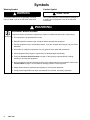
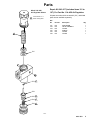
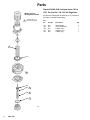
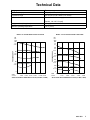
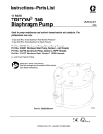
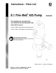
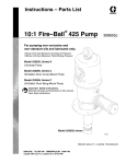
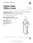
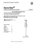
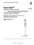
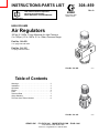
INSTRUCTIONS-PARTS LIST
This manual contains important
warnings and information.
READ AND KEEP FOR REFERENCE.
308–859
Rev. A
First choice when
quality counts.
INSTRUCTIONS
HIGH VOLUME
Air Regulators
300 psi (2.1 MPa, 21 bar) Maximum Air Inlet Pressure
5 to 150 psi (.03 to 1 MPa, 0.3 to 10 bar) Pressure Range
Part No. 114–459
1 in. npt(f) inlet and outlet
Part No. 114–105
1/2 npt(f) inlet and outlet
Part No. 114–459
Part No. 114–105
Table of Contents
Warnings . . . . . . . . . . . . . . . . . . . . . . . . . . . . . . . . . . . . . .
Installation . . . . . . . . . . . . . . . . . . . . . . . . . . . . . . . . . . . .
Operation . . . . . . . . . . . . . . . . . . . . . . . . . . . . . . . . . . . . .
Service . . . . . . . . . . . . . . . . . . . . . . . . . . . . . . . . . . . . . . .
Parts . . . . . . . . . . . . . . . . . . . . . . . . . . . . . . . . . . . . . . . . .
Technical Data . . . . . . . . . . . . . . . . . . . . . . . . . . . . . . . . .
Graco Warranty . . . . . . . . . . . . . . . . . . . . . . . . . . . . . . . .
Toll-Free Graco Phone Number . . . . . . . . . . . . . . . . . .
GRACO INC.
2
3
4
4
5
7
8
8
P.O. BOX 1441 MINNEAPOLIS, MN
COPYRIGHT 1998, GRACO INC.
Graco Inc. is registered to I.S. EN ISO 9001
55440–1441
Symbols
Warning Symbol
Caution Symbol
WARNING
CAUTION
This symbol alerts you to the possibility of serious
injury or death if you do not follow the instructions.
This symbol alerts you to the possibility of damage to
or destruction of equipment if you do not follow the
instructions.
WARNING
EQUIPMENT MISUSE HAZARD
Equipment misuse can cause the equipment to rupture or malfunction and result in serious injury.
INSTRUCTIONS
This equipment is for professional use only.
Read all instruction manuals, tags, and labels before operating the equipment.
Use the equipment only for its intended purpose. If you are uncertain about usage, call your Graco
distributor.
Do not alter or modify this equipment. Use only genuine Graco parts and accessories.
Check equipment daily. Repair or replace worn or damaged parts immediately.
Follow the Pressure Relief Procedure on page 4 if the spray tip clogs and before cleaning,
checking or servicing the equipment.
Do not exceed the maximum working pressure of the lowest rated system component. Refer to the
Technical Data on page 7 for the maximum working pressure of this equipment.
Always wear protective eyewear when operating or servicing this equipment.
Comply with all applicable local, state, and national fire, electrical, and safety regulations.
Installation
Prepare the Site
Install the Regulator
NOTE: Always use Genuine Graco Parts and Accessories, available from your Graco distributor. If you
supply your own accessories, be sure they are adequately sized and pressure rated for your system.
The air regulator controls pump speed and outlet
pressure by adjusting the air pressure to the pump.
Locate the regulator as close as possible to the equipment it serves, but upstream from the pump’s bleedtype master air valve. Install the regulator in the air line
so the air flow is in the direction of the arrow stamped
on the body.
Bring a compressed air supply line from the air compressor to the pump location. Be sure all air hoses are
properly sized and pressure-rated for your system.
Use only electrically conductive hoses.
Before installing any air line components, blow out the
air lines to remove scale and other debris. Use pipe
compound or tape sparingly and only on male threads.
Panel nuts are included with the regulators, for use in
wall mountings.
WARNING
A bleed-type master air valve is required in your
system. Install the valve downstream from the air
regulator. This valve relieves air trapped between it
and the pump when the valve is closed, to help
reduce the risk of serious injury, including fluid
injection and splashing of fluid in the eyes or on the
skin, and injury from moving parts if you are adjusting or repairing the pump.
Operation
6. Lock the gun trigger safety.
Pressure Relief Procedure
WARNING
INJECTION HAZARD
The system pressure must be manually
relieved to prevent the system from
starting or spraying accidentally. Fluid
under high pressure can be injected through the
skin and cause serious injury. To reduce the risk of
an injury from injection, splashing fluid, or moving
parts, follow the Pressure Relief Procedure
whenever you:
are instructed to relieve the pressure,
stop spraying,
7. Open any fluid drain valves (required in your
system), having a container ready to catch the
drainage.
8. Leave the drain valve(s) open until you are ready
to spray again.
If you suspect that the spray tip or hose is completely
clogged, or that pressure has not been fully relieved
after following the steps above, very slowly loosen the
tip guard retaining nut or hose end coupling and relieve
pressure gradually, then loosen completely. Now clear
the tip or hose.
Adjusting the Air Regulator
check or service any of the system equipment,
or install or clean the spray tips.
Open the air regulator slowly. Use it to control pump
speed and fluid pressure. Always use the lowest air
pressure necessary to get the desired results. Higher
pressures cause premature tip and pump wear.
1. Lock the gun trigger safety.
WARNING
2. Close all bleed-type master air valves.
3. Close the air regulator.
4. Unlock the gun trigger safety.
5. Hold a metal part of the gun firmly to the side of a
grounded metal pail, and trigger the gun to relieve
pressure.
COMPONENT RUPTURE HAZARD
To reduce the risk of overpressurizing
your system, which could cause component rupture and serious injury, never
exceed the specified Maximum Incoming Air Pressure of the equipment (see the Technical Data on
page 7 and in the separate component manuals).
Service
Air Regulator Service
Refer to pages 5 and 6. Disassemble the regulator.
Repair Kits are available. Refer to pages 5 and 6.
If the regulator fails to operate, operates roughly, or
vibrates, service it as follows.
Clean the parts with household soap and water or
denatured alcohol. Wipe dry with a clean, soft cloth.
Use compressed air to blow dirt and contaminants out
of the regulator body.
WARNING
To reduce the risk of serious injury whenever you
are instructed to relieve pressure, always follow the
Pressure Relief Procedure on page 4.
Fully relieve pressure and remove the regulator from
the air line.
4
308-859
Inspect all parts for wear or damage. Replace damaged parts.
Lubricate the bearing area, all o-rings, adjusting screw
threads, and spring ends with no. 2 lithium-base
grease. Reassemble the regulator.
Parts
Model 114–459
Air Regulator Shown
Repair Kit 240–817 (includes items 101 to
107). For Part No. 114–459 Air Regulator.
Lubricate with no. 2
lithium-base grease.
Kit parts are marked with an asterisk (101*). Individual
parts are not available separately.
1
1
Ref.
No.
Part No.
Description
101*
102*
103*
104*
105*
106*
N/A
N/A
N/A
N/A
N/A
N/A
DIAPHRAGM
VALVE ASSEMBLY
O-RING
SPRING
O-RING
O-RING
Qty.
1
1
1
1
1
1
101*
103*
1
102*
105*
1
104*
1
106*
1
8387A
Parts
Model 114–105
Air Regulator Shown
1
Lubricate with no. 2
lithium-base grease.
1
101*
102*
103*
1
104*
1
105*
1
6
308-859
Repair Kit 240–818 (includes items 101 to
105). For Part No. 114–105 Air Regulator.
Kit parts are marked with an asterisk (101*). Individual
parts are not available separately.
Ref.
No.
Part No.
Description
101*
102*
103*
104*
105*
N/A
N/A
N/A
N/A
N/A
DIAPHRAGM
VALVE ASSEMBLY
O-RING, valve
SPRING, valve
O-RING, plug
Qty.
1
1
1
1
1
Technical Data
Category
Data
Maximum air input pressure
300 psi (2.1 MPa, 21 bar)
Air pressure range
5 to 150 psi (.03 to 1 MPa, 0.3 to 10 bar)
Air inlet and outlet size
Part No. 114–459: 1 in. npt(f)
Part No. 114–105: 1/2 npt(f)
Gauge port size (air regulator)
1/4 npt(f)
Maximum operating temperature
175_F (79_C)
MODEL 114–105 AIR REGULATOR FLOW CURVE
MODEL 114–459 AIR REGULATOR FLOW CURVE
psi
bar
MPa
100
7.0
0.7
psi
bar
MPa
120
8.4
0.84
PRESSURE DROP
PRESSURE DROP
80
5.6
0.56
80
5.6
0.56
40
2.8
0.28
60
4.2
0.42
40
2.8
0.28
20
1.4
0.14
0
scfm
m#/min
0
80
160
240
320
2.240
4.480
6.720
8.920
400
480
11.200 13.440
AIR FLOW AT INLET PRESSURE OF 150 PSI (0.84 MPa, 8.4 BAR)
0
0
scfm
m#/min
40
80
120
160
200
1.120
2.240
3.360
4.480
5.600
AIR FLOW AT INLET PRESSURE OF 100 PSI (0.7 MPa, 7 BAR)
308-859
7
Graco Standard Warranty
Graco warrants all equipment manufactured by Graco and bearing its name to be free from defects in material and workmanship on the
date of sale by an authorized Graco distributor to the original purchaser for use. With the exception of any special, extended, or limited
warranty published by Graco, Graco will, for a period of twelve months from the date of sale, repair or replace any part of the equipment
determined by Graco to be defective. This warranty applies only when the equipment is installed, operated and maintained in accordance with Graco’s written recommendations.
This warranty does not cover, and Graco shall not be liable for general wear and tear, or any malfunction, damage or wear caused by
faulty installation, misapplication, abrasion, corrosion, inadequate or improper maintenance, negligence, accident, tampering, or substitution of non–Graco component parts. Nor shall Graco be liable for malfunction, damage or wear caused by the incompatibility of
Graco equipment with structures, accessories, equipment or materials not supplied by Graco, or the improper design, manufacture,
installation, operation or maintenance of structures, accessories, equipment or materials not supplied by Graco.
This warranty is conditioned upon the prepaid return of the equipment claimed to be defective to an authorized Graco distributor for
verification of the claimed defect. If the claimed defect is verified, Graco will repair or replace free of charge any defective parts. The
equipment will be returned to the original purchaser transportation prepaid. If inspection of the equipment does not disclose any defect
in material or workmanship, repairs will be made at a reasonable charge, which charges may include the costs of parts, labor, and
transportation.
THIS WARRANTY IS EXCLUSIVE, AND IS IN LIEU OF ANY OTHER WARRANTIES, EXPRESS OR IMPLIED, INCLUDING BUT
NOT LIMITED TO WARRANTY OF MERCHANTABILITY OR WARRANTY OF FITNESS FOR A PARTICULAR PURPOSE.
Graco’s sole obligation and buyer’s sole remedy for any breach of warranty shall be as set forth above. The buyer agrees that no other
remedy (including, but not limited to, incidental or consequential damages for lost profits, lost sales, injury to person or property, or any
other incidental or consequential loss) shall be available. Any action for breach of warranty must be brought within two (2) years of the
date of sale.
Graco makes no warranty, and disclaims all implied warranties of merchantability and fitness for a particular purpose in connection
with accessories, equipment, materials or components sold but not manufactured by Graco. These items sold, but not manufactured
by Graco (such as electric motors, switches, hose, etc.), are subject to the warranty, if any, of their manufacturer. Graco will provide
purchaser with reasonable assistance in making any claim for breach of these warranties.
In no event will Graco be liable for indirect, incidental, special or consequential damages resulting from Graco supplying equipment
hereunder, or the furnishing, performance, or use of any products or other goods sold hereto, whether due to a breach of contract,
breach of warranty, the negligence of Graco, or otherwise.
FOR GRACO CANADA CUSTOMERS
The parties acknowledge that they have required that the present document, as well as all documents, notices and legal proceedings
entered into, given or instituted pursuant hereto or relating directly or indirectly hereto, be drawn up in English. Les parties reconnaissent avoir convenu que la rédaction du présente document sera en Anglais, ainsi que tous documents, avis et procédures judiciaires
exécutés, donnés ou intentés à la suite de ou en rapport, directement ou indirectement, avec les procedures concernées.
Graco Phone Number
TO PLACE AN ORDER, contact your Graco distributor, or call this number to identify the distributor closest to you:
1–800–367–4023 Toll Free
All written and visual data contained in this document reflects the latest product information available at the time of publication.
Graco reserves the right to make changes at any time without notice.
Sales Offices: Minneapolis, Detroit, Los Angeles
Foreign Offices: Belgium, Canada, England, Korea, France, Germany, Hong Kong, Japan
GRACO INC.
P.O. BOX 1441 MINNEAPOLIS, MN
http://www.graco.com
PRINTED IN USA 308–859 May 1998
55440–1441