1
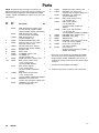
Instructions – Parts List
STAINLESS STEEL
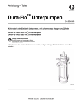
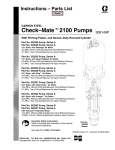
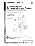
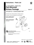
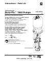
Dura–Flot 1800 Pumps
308148ZAA
ENG
With Severe–Duty Rod and Cylinder
Part Nos. 222895 Pump, Series B, and 253377, Series A
28:1 Ratio, with Quiet Kingt Air Motor
19.3 MPa, 193 bar (2800 psi) Maximum Fluid Working Pressure
0.7 MPa, 7 bar (100 psi) Maximum Air Input Pressure
Part No. 222897 Pump, Series B,
with Viscountr Hydraulic Motor
18 MPa, 179 bar (2600 psi) Maximum Fluid Working Pressure
10 MPa, 103 bar (1500 psi) Maximum Hydraulic Input Pressure
Part Nos. C59792 and 222939 Pumps, Series B,
Part Nos. 233069}, 233070}, 234667}, 234824},
241957, 243689, 246923, 246924, 246989{,
246990{, 246991{, 246992{, 253842, Pumps, Series A,
45:1 Ratio, with Premiert Air Motor
31 MPa, 310 bar (4500 psi) Maximum Fluid Working Pressure
0.7 MPa, 7 bar (100 psi) Maximum Air Input Pressure
{ Not
} Not
certified
nor
certified
Important Safety Instructions
Read all warnings and instructions in this manual.
Save these instructions.
See page 2 for Table of Contents.
Part No. 222895 Shown
0566C
Table of Contents
Warnings . . . . . . . . . . . . . . . . . . . . . . . . . . . . . . . . . . . . . . 3
Installation . . . . . . . . . . . . . . . . . . . . . . . . . . . . . . . . . . . . . 7
Air-Powered Pumps . . . . . . . . . . . . . . . . . . . . . . . . . 8
Hydraulic-Powered Pumps . . . . . . . . . . . . . . . . . . 10
Operation/Maintenance . . . . . . . . . . . . . . . . . . . . . . . . 13
All Pumps . . . . . . . . . . . . . . . . . . . . . . . . . . . . . . . . 13
Air-Powered Pumps . . . . . . . . . . . . . . . . . . . . . . . . 14
Hydraulic-Powered Pumps . . . . . . . . . . . . . . . . . . 15
Troubleshooting Chart . . . . . . . . . . . . . . . . . . . . . . . . . 16
Service . . . . . . . . . . . . . . . . . . . . . . . . . . . . . . . . . . . . . . 17
Required Tools . . . . . . . . . . . . . . . . . . . . . . . . . . . . 17
Disconnecting the Displacement Pump . . . . . . . 17
2
308148
Reconnecting the Displacement Pump . . . . . . . . 18
Displacement Pump Service . . . . . . . . . . . . . . . . 20
Parts Drawings and Parts Lists . . . . . . . . . . . . . . . . . . . .
Pump Assemblies . . . . . . . . . . . . . . . . . . . . . . . . . . 25
Displacement Pumps . . . . . . . . . . . . . . . . . . . . . . . 28
Packing Conversion Kits . . . . . . . . . . . . . . . . . . . . 32
Technical Data . . . . . . . . . . . . . . . . . . . . . . . . . . . . . . . . 33
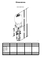
Dimensions . . . . . . . . . . . . . . . . . . . . . . . . . . . . . . . . . . . 38
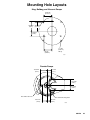
Mounting Hole Layouts . . . . . . . . . . . . . . . . . . . . . . . . . 39
Warranty . . . . . . . . . . . . . . . . . . . . . . . . . . . . . . . . . . . . . 40
Graco Information . . . . . . . . . . . . . . . . . . . . . . . . . . . . . 40
Symbols
Warning Symbol
Caution Symbol
WARNING
CAUTION
This symbol alerts you to the possibility of serious
injury or death if you do not follow the instructions.
This symbol alerts you to the possibility of damage to
or destruction of equipment if you do not follow the
instructions.
WARNING
EQUIPMENT MISUSE HAZARD
Equipment misuse can cause the equipment to rupture or malfunction and result in serious injury.
INSTRUCTIONS
D This equipment is for professional use only.
D Read all instruction manuals, tags, and labels before operating the equipment.
D Use the equipment only for its intended purpose. If you are uncertain about usage, call your Graco
distributor.
D Do not alter or modify this equipment. Use only genuine Graco parts and accessories.
D Check equipment daily. Repair or replace worn or damaged parts immediately.
D Do not exceed the maximum working pressure of the lowest rated system component. Refer to the
Technical Data on pages 33–37 for the maximum working pressure of this equipment.
D Use fluids and solvents which are compatible with the equipment wetted parts. Refer to the Technical Data section of all equipment manuals. Read the fluid and solvent manufacturer’s warnings.
D Do not kink or overbend hoses or use hoses to pull equipment.
D Route hoses away from traffic areas, sharp edges, moving parts, and hot surfaces. Do not expose
Graco hoses to temperatures above 82_C (180_F) or below –40_C (–40_F).
D Wear hearing protection when operating this equipment.
D Do not lift pressurized equipment.
D Comply with all applicable local, state, and national fire, electrical, and safety regulations.
308148
3
WARNING
SKIN INJECTION HAZARD
Spray from the gun/valve, hose leaks, or ruptured components can inject fluid into your body and
cause extremely serious injury, including the need for amputation. Fluid splashed in the eyes or on the
skin can also cause serious injury.
D Fluid injected into the skin might look like just a cut, but it is a serious injury. Get immediate surgical treatment.
D Do not point the gun/valve at anyone or at any part of the body.
D Do not put your hand or fingers over the spray tip/nozzle.
D Do not stop or deflect leaks with your hand, body, glove or rag.
D Do not “blow back” fluid; this is not an air spray system.
D Always have the tip guard and the trigger guard on the gun/valve when spraying.
D Be sure the gun/valve trigger safety operates before spraying.
D Lock the gun/valve trigger safety when you stop spraying.
D Follow the Pressure Relief Procedure on page 13 whenever you: are instructed to relieve pressure; stop spraying; clean, check, or service the equipment; and install or clean the spray tip/
nozzle.
D Tighten all fluid connections before operating the equipment.
D Check the hoses, tubes, and couplings daily. Replace worn, damaged, or loose parts immediately.
Permanently coupled hoses cannot be repaired; replace the entire hose.
D Use only Graco approved hoses. Do not remove any spring guard that is used to help protect the
hose from rupture caused by kinks or bends near the couplings.
MOVING PARTS HAZARD
Moving parts, such as the air motor piston, can pinch or amputate your fingers.
D Keep clear of all moving parts when starting or operating the pump.
D Before servicing the equipment, follow the Pressure Relief Procedure on page 13 to prevent the
equipment from starting unexpectedly.
4
308148
WARNING
FIRE AND EXPLOSION HAZARD
Improper grounding, poor ventilation, open flames or sparks can cause a hazardous condition and
result in a fire or explosion and serious injury.
D Ground the equipment and the object being sprayed. Refer to Grounding on page 7.
D If there is any static sparking or you feel an electric shock while using this equipment, stop spraying immediately. Do not use the equipment until you identify and correct the problem.
D Provide fresh air ventilation to avoid the buildup of flammable fumes from solvents or the fluid
being sprayed.
D Keep the spray area free of debris, including solvent, rags, and gasoline.
D Electrically disconnect all equipment in the spray area.
D Extinguish all open flames or pilot lights in the spray area.
D Do not smoke in the spray area.
D Do not turn on or off any light switch in the spray area while operating or if fumes are present.
D Do not operate a gasoline engine in the spray area.
D Keep a fire extinguisher in the work area.
TOXIC FLUID HAZARD
Hazardous fluid or toxic fumes can cause serious injury or death if splashed in the eyes or on the skin,
inhaled, or swallowed.
D Know the specific hazards of the fluid you are using.
D Store hazardous fluid in an approved container. Dispose of hazardous fluid according to all local,
state and national guidelines.
D Always wear protective eyewear, gloves, clothing and respirator as recommended by the fluid and
solvent manufacturer.
308148
5
Notes
6
308148
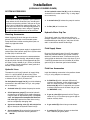
Installation
7. Object being sprayed: according to your local
code.
Grounding
WARNING
FIRE AND EXPLOSION HAZARD
Before operating the pump, ground the
system as explained below. Also read
the section FIRE AND EXPLOSION
HAZARD on page 5.
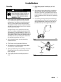
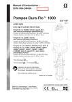
1. King Pumps: use a ground wire and clamp. See
Fig. 1. Remove the ground screw (Z) and insert
through eye of ring terminal at the end of ground
wire (Y). Fasten ground screw back onto pump
and tighten securely. Connect the other end of the
wire to a true earth ground. Order Part No. 222011
Ground Wire and Clamp.
8. All solvent pails used when flushing, according to
your local code. Use only metal pails, which are
conductive, placed on a grounded surface. Do not
place the pail on a nonconductive surface, such as
paper or cardboard, which interrupts the grounding
continuity.
9. To maintain grounding continuity when flushing or
relieving pressure, always hold a metal part of the
spray gun/dispensing valve firmly to the side of a
grounded metal pail, then trigger the gun/valve.
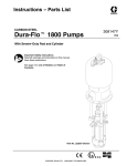
All Other Pumps: use a ground wire and clamp.
See Fig. 2. Loosen the grounding lug locknut (W)
and washer (X). Insert one end of a 1.5 mm@ (12
ga) minimum ground wire (Y) into the slot in lug (Z)
and tighten the locknut securely. Connect the other
end of the wire to a true earth ground. Order Part
No. 237569 Ground Wire and Clamp.
2. Air and hydraulic hoses: use only electrically
conductive hoses.
Z
Y
TI1052
Fig. 1
W
3. Fluid hoses: use only grounded fluid hoses.
X
4. Air compressor or hydraulic power supply: follow
manufacturer’s recommendations.
Y
Z
5. Spray gun/dispensing valve: grounding is obtained
through connection to a properly grounded fluid
hose and pump.
6. Fluid supply container: according to your local
code.
0864
Fig. 2
308148
7
Installation
(AIR-POWERED PUMPS)
NOTE: Reference numbers and letters in parentheses
in the text refer to the callouts in the figures and the
parts drawing.
NOTE: Accessories are available from your Graco
distributor. If you supply your own accessories, be sure
they are adequately sized and pressure-rated to meet
the system’s requirements.
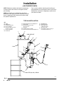
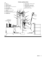
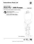
Fig. 3 is only a guide for selecting and installing system components and accessories. Contact your Graco
distributor for assistance in designing a system to suit
your particular needs.
TYPICAL INSTALLATION
KEY
A
B
C
D
E
F
G
Pump
Wall Bracket
Pump Runaway Valve
Air Line Lubricator
Bleed-Type Master Air Valve
(required, for pump)
Pump Air Regulator
Air Manifold
H
J
K
Electrically Conductive Air Supply Hose
Air Line Filter
Bleed-Type Master Air Valve
(for accessories)
L Fluid Filter
M Fluid Drain Valve (required)
N Electrically Conductive Fluid Supply Hose
J
P
R
S
T
Y
Fluid Whip Hose
Gun/Valve Swivel
Airless Spray Gun
or Dispensing Valve
Drum Suction Kit
Ground Wire (required; see page 7
for installation instructions)
K
MAIN AIR LINE
D
Y
A
H
C
E
R
F
G
L P
S
B
M
N
T
200 LITER (55 GAL.) DRUM
0626C
Fig. 3
8
308148
Installation
(AIR-POWERED PUMPS)
SYSTEM ACCESSORIES
WARNING
A bleed-type master air valve (E) and a fluid drain
valve (M) are required in your system. These
accessories help reduce the risk of serious injury,
including skin injection and splashing of fluid in the
eyes or on the skin, and injury from moving parts if
you are adjusting or repairing the pump.
The bleed-type master air valve relieves air trapped
between this valve and the pump after the air is
shut off. Trapped air can cause the pump to cycle
unexpectedly. Locate the valve close to the pump.
D
An air line lubricator (D) provides automatic air
motor lubrication.
D
A bleed-type master air valve (E) is required in
your system to relieve air trapped between it and
the air motor when the valve is closed (see the
WARNING above). Be sure the bleed valve is easily accessible from the pump, and is located
downstream from the air regulator.
D
An air regulator (F) controls pump speed and outlet pressure by adjusting the air pressure to the
pump. Locate the regulator close to the pump, but
upstream from the bleed-type master air valve.
D
A pump runaway valve (C) senses when the
pump is running too fast and automatically shuts
off the air to the motor. A pump which runs too fast
can be seriously damaged.
D
An air manifold (G) has a swivel air inlet. It
mounts to a wall bracket, and provides ports for
connecting lines to air-powered accessories.
D
An air line filter (J) removes harmful dirt and
moisture from the compressed air supply.
D
A second bleed-type air valve (K) isolates the air
line accessories for servicing. Locate upstream
from all other air line accessories.
The fluid drain valve assists in relieving fluid pressure in the displacement pump, hose, and gun.
Triggering the gun to relieve pressure may not be
sufficient.
Air and Fluid Hoses
Be sure all air hoses (H) and fluid hoses (N and P) are
properly sized and pressure-rated for your system.
Use only electrically conductive hoses. Fluid hoses
must have spring guards on both ends. Use a whip
hose (P) and a swivel (R) between the main fluid hose
(N) and the gun/valve (S) to allow freer gun/valve
movement.
Mounting Accessories
WARNING
For Models 222939 and C59792 Premier Pumps,
do not lift the pump by the lift ring when the total
weight exceeds 550 lb (250 kg).
Fluid Line Accessories
Install the following accessories in the positions shown
in Fig. 3, using adapters as necessary:
D
A fluid filter (L) with a 60 mesh (250 micron)
stainless steel element, to filter particles from the
fluid as it leaves the pump. It includes a fluid
drain valve (M), which is required in your system
to relieve fluid pressure in the hose and gun (see
the WARNING at left).
D
A gun or valve (S) dispenses the fluid. The gun
shown in Fig. 3 is an airless spray gun for light to
medium viscosity fluids.
D
A gun swivel (R) allows freer gun movement.
D
A suction kit (T) allows the pump to draw fluid
from a 200 liter (55 gallon) drum.
Mount the pump (A) to suit the type of installation
planned. Fig. 3 illustrates a wall-mounted system.
Pump dimensions and the mounting hole layout are
shown on pages 38 and 39.
If you are using an elevator or a cart, refer to the
separate manuals supplied with those components for
installation and operation instructions.
Air Line Accessories
Install the following accessories in the order shown in
Fig. 3, using adapters as necessary:
308148
9
Installation
(HYDRAULIC-POWERED PUMPS)
NOTE: Reference numbers and letters in parentheses
in the text refer to the callouts in the figures and the
parts drawing.
NOTE: Accessories are available from your Graco
distributor. If you supply your own accessories, be sure
they are adequately sized and pressure-rated to meet
the system’s requirements.
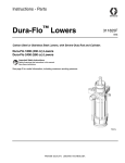
Fig. 4 is only a guide for selecting and installing system components and accessories. Contact your Graco
distributor for assistance in designing a system to suit
your particular needs.
CAUTION
It is very important to keep the hydraulic supply
system clean at all times. Be sure that all hydraulic
fluid lines are absolutely clean. Blow out the lines
with air and flush thoroughly with solvent before
connecting to the hydraulic motor, to avoid introducing harmful contaminants into the motor. Plus the
hydraulic lines immediately when they are disconnected.
Do not exceed 37.8 liter/min (10 gpm) hydraulic oil
volume to the motor, to avoid pump stalling.
For optimum pump performance, keep the temperature of the hydraulic oil below 54_ C (130_ F)
10
308148
TYPICAL INSTALLATION
KEY
A
B
C
D
E
F
G
H
J
K
L
M
N
P
R
Pump
Wall Bracket
Hydraulic Supply Line
Hydraulic Return Line
Drain Line (from pressure reducing valve)
Pressure Gauge
Flow Control Valve
Pressure Reducing Valve
Accumulator
Drain Line (from motor drip pan)
Fluid Filter
Fluid Drain Valve (required)
Electrically Conductive Fluid Supply Hose
Fluid Whip Hose
Gun/Valve Swivel
S
T
U
V
Y
Airless Spray Gun or Dispensing Valve
Drum Suction Kit
Hydraulic Supply Line Shutoff Valve
Hydraulic Return Line Shutoff Valve
Ground Wire (required, see page 7 for
installation instructions)
AA Hydraulic Return Line Filter
J
H
F
V
A
E
S
Y
U
R
C
L
G
P
B
HYDRAULIC
POWER SUPPLY
N
M
D
AA
DRAINAGE
CONTAINER
K
T
200 LITER
(55 GAL.) DRUM
0627B
Fig. 4
308148
11
Installation
(HYDRAULIC-POWERED PUMPS)
SYSTEM ACCESSORIES
WARNING
A fluid drain valve (M) is required in your system to
help reduce the risk of serious injury, including skin
injection and splashing of fluid in the eyes or on the
skin if you are adjusting or repairing the pump. The
fluid drain valve assists in relieving fluid pressure in
the displacement pump, hose, and gun. Triggering
the gun to relieve pressure may not be sufficient.
On the hydraulic return line (D), install the following
accessories in the order shown in Fig. 4, using adapters as necessary:
D
A shutoff valve (V) isolates the pump for service.
D
A filter (AA) of 10 micron size.
Hydraulic Motor Drip Pan
Mounting Accessories
Mount the pump (A) to suit the type of installation
planned. Fig. 4 illustrates a wall-mounted system.
Pump dimensions and the mounting hole layout are
shown on pages 38 and 39.
The hydraulic motor has a drip pan to collect any
leakage. Connect a 6 mm (1/4 in.) ID drain line (K) to
the barbed fitting on the drip pan, and place the free
end in a container to receive the drainage.
Filters
Be sure your hydraulic power supply is equipped with a
suction filter to the hydraulic pump and a system return
line filter (AA) of 10 micron size.
Carefully follow the manufacturer’s recommendations
on reservoir and filter cleaning, and periodic changes
of hydraulic fluid. Use only Graco-approved hydraulic
oil. Order Part No. 169236, 5 gal. (19 liter) or 207428,
1 gal. (3.8 liter). Do not substitute a lower grade oil or
one with a lower flash point.
Hydraulic Lines
The motor has a 3/4 npt(f) hydraulic oil supply fitting,
and a 1 in. npt(f) hydraulic oil return fitting. Use a
minimum 13 mm (1/2 in.) ID hydraulic supply line, and
a minimum 22 mm (7/8 in.) ID return line.
On the hydraulic supply line (C), install the following
accessories in the order shown in Fig. 4, using adapters as necessary:
D
A shutoff valve (U) isolates the pump for service.
D
A fluid pressure gauge (F) to monitor hydraulic
oil pressure to the motor and to avoid overpressurizing the motor or displacement pump, and a pressure- and temperature-compensated flow control valve (G) to prevent the motor from running
too fast and possibly damaging itself.
D
D
A pressure reducing valve (H), with a drain line
(E) run directly to the hydraulic return line (D).
An accumulator (J) to reduce the hammering effect caused by the motor reversing direction.
12
308148
Fluid Supply Hoses
Be sure all fluid supply hoses (N and P) are properly
sized and pressure-rated for your system. Use only
electrically conductive hoses. Fluid hoses must have
spring guards on both ends. Use a whip hose (P) and
a swivel (R) between the main fluid hose (N) and the
gun/valve (S) to allow freer gun/valve movement.
Fluid Line Accessories
Install the following accessories in the positions shown
in Fig. 4, using adapters as necessary:
D
A fluid filter (L) with a 60 mesh (250 micron)
stainless steel element, to filter particles from the
fluid as it leaves the pump. It includes a fluid
drain valve (M), which is required in your system
to relieve fluid pressure in the hose and gun (see
the WARNING at left).
D
A gun or valve (S) dispenses the fluid. The gun
shown in Fig. 3 is an airless spray gun for light to
medium viscosity fluids.
D
A gun swivel (R) allows freer gun movement.
D
A suction kit (T) allows the pump to draw fluid
from a 200 liter (55 gallon) drum.
Operation/Maintenance
(ALL PUMPS)
Pressure Relief Procedure
WARNING
SKIN INJECTION HAZARD
Fluid under high pressure can be injected through the skin and cause
serious injury. To reduce the risk of an
injury from injection, splashing fluid, or moving
parts, follow the Pressure Relief Procedure
whenever you:
D
D
D
D
are instructed to relieve the pressure,
stop spraying/dispensing,
check or service any of the system equipment,
or install or clean the spray tip/nozzle.
FLUSHING THE PUMP
The pump is tested with lightweight oil, which is left in
to protect the pump parts. If the fluid you are using
may be contaminated by the oil, flush it out with a
compatible solvent before using the pump.
WARNING
For your safety, read the warning section, FIRE
AND EXPLOSION HAZARD on page 5 before
flushing, and follow all recommendations given
there.
1. Lock the gun/valve trigger safety.
2. Shut off the air or hydraulic supply to the pump.
3. In air-powered systems, close the bleed-type
master air valve (required in your system). In
hydraulic-powered systems, close the hydraulic
supply line valve first, then the return line valve.
4. Unlock the gun/valve trigger safety.
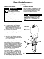
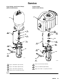
Model 222895
Shown
1
Bleed hole must
face down.
5. Hold a metal part of the gun/valve firmly to the side
of a grounded metal pail, and trigger the gun/valve
to relieve pressure.
6. Lock the gun/valve trigger safety.
7. Open the drain valve (required in your system)
and/or the pump bleeder valve, having a container
ready to catch the drainage.
3
8. Leave the drain valve open until you are ready to
spray/dispense again.
If you suspect that the spray tip/nozzle or hose is
completely clogged, or that pressure has not been fully
relieved after following the steps above, very slowly
loosen the tip guard retaining nut, nozzle, or hose end
coupling and relieve pressure gradually, then loosen
completely. Now clear the tip/nozzle or hose.
34, 35
1
104
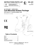
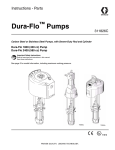
PACKING NUT/WET-CUP
Fill the packing nut/wet-cup (3) 1/3 full with Graco
Throat Seal Liquid (TSL) or compatible solvent. See
Fig. 5. Using the supplied wrench (104), adjust the
packing nut weekly so it is just snug; do not overtighten. Follow the Pressure Relief Procedure Warning
above before adjusting the packing nut.
0566C
Fig. 5
308148
13
Operation/Maintenance
(AIR-POWERED PUMPS)
Starting and Adjusting the Pump
1. Refer to Fig. 3 on page 8. Connect the suction kit
(T) to the pump’s fluid inlet, and place the tube into
the fluid supply.
2. Be sure the air regulator (F) is closed. Then open
the pump’s bleed-type master air valve (E). Hold a
metal part of the spray gun/dispensing valve (S)
firmly to the side of a grounded metal pail and hold
the trigger open. Now slowly open the air regulator
until the pump starts.
3. Cycle the pump slowly until all air is pushed out
and the pump and hoses are fully primed. Release
the gun/valve trigger and lock the trigger safety.
The pump should stall against pressure when the
trigger is released.
WARNING
SKIN INJECTION HAZARD
To reduce the risk of skin injection, do not use your
hand or fingers to cover the bleed hole on the
underside of the bleeder valve body (34) when
priming the pump. Use a crescent wrench to open
and close the bleeder plug (35). Keep your hands
away from the bleed hole.
4. If the pump fails to prime properly, open the
bleeder valve (35) slightly. Use the bleed hole on
the underside of the valve body (34) as a priming
valve until the fluid appears at the hole. See Fig. 5.
Close the plug (35).
NOTE: When changing fluid containers with the hose
and gun already primed, open the bleeder valve (24),
to assist in priming the pump and venting air before it
enters the hose. Close the bleeder valve when all air
has been eliminated.
5. With the pump and lines primed, and with adequate air pressure and volume supplied, the pump
will start and stop as the gun/valve is opened and
closed. In a circulating system, the pump will
speed up or slow down on demand, until the air
supply is shut off.
14
308148
6. Use the air regulator to control the pump speed
and the fluid pressure. Always use the lowest air
pressure necessary to get the desired results.
Higher pressures cause premature tip/nozzle and
pump wear.
WARNING
To reduce the risk of overpressurizing your system,
which could result in component rupture and cause
serious injury, never exceed the specified Maximum Incoming Air Pressure to the pump (see the
Technical Data on pages 33–37).
7. Never allow the pump to run dry of the fluid being
pumped. A dry pump will quickly accelerate to a
high speed, possibly damaging itself. A pump
runaway valve (C), which shuts off the air supply to
the pump if the pump accelerates beyond the
pre-set speed, is available. See Fig. 3 on page 8.
If your pump accelerates quickly, or is running too
fast, stop it immediately and check the fluid supply.
If the supply container is empty and air has been
pumped into the lines, refill the container and
prime the pump and the lines with fluid, or flush
and leave it filled with a compatible solvent. Be
sure to eliminate all air from the fluid system.
Shutdown and Care of the Pump
WARNING
To reduce the risk of serious injury whenever you
are instructed to relieve pressure, always follow the
Pressure Relief Procedure on page 13.
For overnight shutdown, relieve the pressure. Stop
the pump at the bottom of its stroke to prevent fluid
from drying on the exposed displacement rod and
damaging the throat packings.
Always flush the pump before the fluid dries on the
displacement rod. Flush with water or a compatible
solvent. Relieve the pressure after flushing.
Operation/Maintenance
(HYDRAULIC-POWERED PUMPS)
Starting and Adjusting the Pump
1. Refer to Fig. 4 on page 11. Connect the suction kit
(T) to the pump’s fluid inlet, and place the tube into
the fluid supply.
2. Check the hydraulic fluid level before each use,
and add fluid as necessary.
3. Make certain that the supply line shutoff valve (U)
and the return line shutoff valve (V) are closed.
4. Start the hydraulic power supply.
5. Hold a metal part of the gun/valve (S) firmly to the
side of a grounded metal pail and hold the trigger
open.
6. Open the return line shutoff valve (V) first, then
slowly open the supply line shutoff valve (U).
7. Cycle the pump slowly until all air is pushed out
and the pump and hoses are fully primed. Release
the gun/valve trigger and engage the safety latch.
The pump should stall against pressure when the
trigger is released.
WARNING
SKIN INJECTION HAZARD
To reduce the risk of skin injection, do not use your
hand or fingers to cover the bleed hole on the
underside of the bleeder valve body (34) when
priming the pump. Use a crescent wrench to open
and close the bleeder plug (35). Keep your hands
away from the bleed hole.
8. If the pump fails to prime properly, open the
bleeder valve (35) slightly. Use the bleed hole, on
the underside of the body (34), as a priming valve
until the fluid appears at the hole. See Fig. 5.
Close the plug (35).
NOTE: When changing fluid containers with the hose
and gun already primed, open the bleeder valve (24),
to assist in priming the pump and venting air before it
enters the hose. Close the bleeder valve when all air
has been eliminated.
9. With the pump and lines primed, and with adequate hydraulic volume supplied, the pump will
start and stop as the gun/valve is opened and
closed. In a circulating system, the pump will
speed up or slow down on demand, until the
hydraulic power supply is shut off.
10. Use the fluid pressure gauge (F) and flow control
valve (G) to control the pump speed and the fluid
outlet pressure. Always use the lowest hydraulic
flow and pressure necessary to get the desired
results. Higher pressures cause premature tip/nozzle and pump wear.
WARNING
To reduce the risk of overpressurizing your system,
which could result in component rupture and cause
serious injury, never exceed 10 MPa, 103 bar
(1500 psi) Maximum Hydraulic Input Pressure to
the pump, or 14.0 MPa, 140 bar (2000 psi) Maximum Fluid Working Pressure (see the Technical
Data on page 37).
To prevent overpressurizing the hydraulic motor or
its seals, always shut off the supply line valve (U)
first, then shut off the return line valve (V).
CAUTION
Do not allow the hydraulic oil temperature to exceed
54_ C (130_ F). The pump seals will wear faster and
leakage may occur if the pump is operated at higher
oil temperatures.
11. Never allow the pump to run dry of the fluid being
pumped. A dry pump will quickly accelerate to a
high speed, possibly damaging itself. If your pump
accelerates quickly, or is running too fast, stop it
immediately and check the fluid supply. If the
supply container is empty and air has been
pumped into the lines, refill the container and
prime the pump and the lines with fluid, or flush
and leave it filled with a compatible solvent. Be
sure to eliminate all air from the fluid system.
Shutdown and Care of the Pump
WARNING
To reduce the risk of serious injury whenever you
are instructed to relieve pressure, always follow the
Pressure Relief Procedure on page 13.
For overnight shutdown, relieve the pressure. Stop
the pump at the bottom of the stroke to prevent fluid
from drying on the exposed displacement rod and
damaging the throat packings.
Always flush the pump before the fluid dries on the
displacement rod. Flush with water or a compatible
solvent. Relieve the pressure after flushing.
308148 15
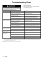
Troubleshooting Chart
WARNING
To reduce the risk of serious injury whenever you
are instructed to relieve pressure, always follow the
Pressure Relief Procedure on page 13.
1. Relieve the pressure.
2. Check all possible causes and problems before
disassembling the pump.
PROBLEM
CAUSE
Pump fails to operate
Restricted line or inadequate air/hydraulic Clear; increase air/hydraulic supply.
supply; closed or clogged valves
Check that valves are open.
SOLUTION
Obstructed fluid hose or gun/valve;
fluid hose ID is too small
Open, clear*; use hose with larger ID.
Fluid dried on the displacement rod
Clean; always stop pump at bottom of stroke;
keep wet-cup 1/3 filled with compatible solvent.
Dirty, worn, or damaged motor parts
Clean or repair; see separate motor manual.
Pump operates, but out- Restricted line or inadequate air/hydraulic Clear; increase air/hydraulic supply.
put low on both strokes
supply; closed or clogged valves
Check that valves are open.
Obstructed fluid hose or gun/valve;
fluid hose ID is too small
Open, clear*; use hose with larger ID.
Bleeder valve open
Close.
Fluid too heavy for pump priming
Use bleeder valve (see pages 14 and 15); use ram.
Worn packings in displacement pump
Replace packings.
Pump operates, but out- Held open or worn intake valve
put low on downstroke
Fluid too heavy for pump priming
Clear valve; service.
Use bleeder valve (see pages 14 and 15); use ram.
Pump operates, but out- Held open or worn piston valve or packings. Clear valve; replace packings.
put low on upstroke
Erratic or accelerated Exhausted fluid supply
pump speed
Fluid too heavy for pump priming
Refill and prime.
Use bleeder valve (see pages 14 and 15); use ram.
Held open or worn piston valve or packings. Clear valve; replace packings.
Held open or worn intake valve
*
To determine if the fluid hose or gun is obstructed, relieve the pressure. Disconnect the fluid hose and place a container at the pump fluid
outlet to catch any fluid. Turn on the air/hydraulic power just enough to start the pump. If the pump starts when the air/hydraulic power is turned
on, the obstruction is in the fluid hose or gun.
NOTE: If you experience air motor icing, contact your Graco distributor.
16
Clear valve; service.
308148
Service
REQUIRED TOOLS
D
D
D
D
D
D
D
D
D
D
D
Set of socket wrenches
Set of adjustable wrenches
24 in. adjustable wrench
Torque wrench
Rubber mallet
Arbor press
Soft wooden block (approx. 1 square foot in size)
Large vise, with soft jaws
Thread lubricant
Anti-seize lubricant 222955
LoctiteR 2760t or equivalent
NOTE: Service Tool 109507 is available as an accessory. The tool fits over the top of the displacement rod,
making it easier to apply a 24 inch adjustable wrench
or 3/4 in. drive socket when connecting or disconnecting the rod from the piston assembly.
DISCONNECTING DISPLACEMENT PUMP
WARNING
To reduce the risk of serious injury whenever you
are instructed to relieve pressure, always follow the
Pressure Relief Procedure on page 13.
1. Flush the pump, if possible. Stop the pump at the
bottom of its stroke. Relieve the pressure.
2. Disconnect the air or hydraulic hose. Plug all
hydraulic hoses immediately, to prevent contamination of the hydraulic system. Hold the fluid outlet
fitting (4) with a wrench to keep it from being
loosened while you disconnect the fluid hose.
WARNING
For Models 222939 and C59792 Premier Pumps,
do not lift the pump by the lift ring when the total
weight exceeds 550 lb (250 kg).
3. Disconnect the displacement pump (105) from the
motor (101) as follows. Be sure to note the relative
position of the pump’s fluid outlet to the air or
hydraulic inlet of the motor. If the motor does not
require servicing, leave it attached to its mounting.
CAUTION
Be sure to use at least two people when lifting,
moving, or disconnecting the pump. The pump is too
heavy for one person. If you are disconnecting the
displacement pump from a motor which is still
mounted (for example, on a wall bracket), be sure to
support the displacement pump while it is being
disconnected, to prevent it from falling and causing
injury or property damage. Do this by securely
bracing the pump, or by having at least two people
hold it while another disconnects it.
4. Using adjustable wrenches, unscrew the coupling
nut (103) from the connecting rod adapter (102).
Remove the coupling collars (108). Take care not
to lose or drop them. See Fig. 6.
5. Hold the tie rod flats with a wrench to keep the
rods from turning. Unscrew the nuts (106) from the
tie rods (107). Carefully remove the displacement
pump (105) from the motor (101).
6. Refer to page 20 for displacement pump service.
To service the air or hydraulic motor, refer to the
separate motor manual, supplied.
308148
17
Service
RECONNECTING DISPLACEMENT PUMP
WARNING
To reduce the risk of pinching or injuring hands or
fingers caught between the hydraulic motor drip
pan and the coupling nut, always use connecting
rod adapter 184595 and tie rods 184596 on Model
222897 Viscount Pump. Never use connecting rod
adapter 184451 and tie rods 184452 on Model
222897; those parts do not allow sufficient clearance between the drip pan and coupling nut.
1. Use at least two people to hold the displacement
pump while another reconnects it to the motor (see
the CAUTION at left). Orient the pump’s fluid
outlet to the air or hydraulic inlet as was noted in
step 3 under Disconnecting the Displacement
Pump. Position the displacement pump (105) on
the tie rods (107). See Fig. 6.
2. Screw the nuts (106) onto the tie rods (107) and
torque as noted in Fig. 6.
3. Place the coupling nut (103) on the displacement
rod (1), then place the coupling collars (108) into
the nut. Screw the coupling nut onto the connecting rod adapter (102) loosely. Hold the connecting
rod adapter flats with a wrench to keep it from
turning. Use an adjustable wrench to tighten the
coupling nut. Torque as noted in Fig. 6.
NOTE: On Premier models, ensure that the rod adapter (102) has not loosened during maintenance. Proper
torque is necessary to prevent the rod adapter from
loosening during the pump operation.
4. Torque the packing nut (3) to 135–169 N.m
(100–125 ft–lb).
If the rod adapter (102) has loosened during maintenance, remove the adapter and apply LoctiteR 2760t
(or equivalent) to the rod adapter and air motor piston
threads, and then torque as specified in Fig. 6.
6. Turn on the air or hydraulic power supply. On
hydraulic pumps, open the hydraulic return line
valve first, then the supply line valve. Run the
pump slowly to ensure that it is operating properly.
18
308148
5. Reconnect all hoses. Reconnect the ground wire if
it was disconnected. Fill the wet-cup (3) 1/3 full of
Graco Throat Seal Liquid or compatible solvent.
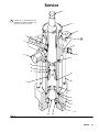
Service
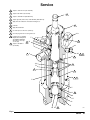
King, Bulldog, and Viscount Pumps
(Model 222895 Shown)
Premier Pumps
(Model 222939 Shown)
101
101
1
102
3
7
107
102
6
108
1
103
108
1
3
103
2
5
107
3
3
6
1
2
106
105
4
5
106
105
104
4
4
0567C
104
4
1
Torque to 196–210 N.m (145–155 ft–lb)
5
Torque to 129–142 N.m (95–105 ft–lb)
2
Torque to 135–169 N.m (100–125 ft–lb)
6
Torque to 312–340 N.m (230–250 ft–lb)
3
Torque to 192–142 N.m (95–105 ft–lb)
7
Apply LoctiteR 2760t (or equivalent) to threads.
4
Square hole is for use with torque wrench.
01397D
Fig. 6
308148
19
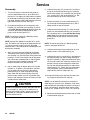
Service
DISPLACEMENT PUMP SERVICE
Disassembly
When disassembling the pump, lay out all the removed
parts in sequence, to ease reassembly. Clean all parts
with a compatible solvent and inspect them for wear or
damage. Refer to Fig. 7.
NOTE: Repair Kits are available to replace the throat
(T) and piston (P) packings, and to replace the o-rings
and cylinder seals. For the best results, use all the new
parts in the kit. Kit parts are marked with an asterisk,
for example (11*). These kits can also be used to
convert the pump to different packing materials. Refer
to pages 30 and 32.
NOTE: Standard Displacement Pumps 222805 and
687055 use stainless steel capscrews (20) with washers (33). Optional Pumps 222989, 236227 and 236231
use carbon steel cap screws and do not include the
washers.
1. Stand the displacement pump upright in a large
vise. Loosen, but do not remove, the packing nut
(3). Remove the six long cap screws (20) and
washers (33, if present), using a socket wrench.
2. Lift the outlet housing (19) straight up off the
pump. Be careful not to scratch the displacement
rod (1) while removing the housing.
3. Lift the cylinder (7), displacement rod (1), and
piston assembly off the intake housing (17).
4. Remove the seal (6), ball guide (14), intake ball
(16), intake seat housing (15), and o-ring (27) from
the intake housing (17). Inspect the ball (16) and
the ball seat (A) on the housing (15) for wear or
damage.
5. Remove the seal (6) from the bottom of the outlet
housing (19). Unscrew the packing nut (3). Remove the glands and v-packings (T) from the
housing. Do not remove the outlet fitting (4) and
o-ring (5) unless they need replacement.
6. Unscrew the handle of the bleeder valve (24)
completely from the valve housing. Clean the valve
threads and the bleed hole in the valve housing. It
is not necessary to remove the valve housing from
the outlet housing (19).
20
308148
7. Stand the cylinder (7) upright on a wooden block.
Using a rubber mallet or an arbor press, drive the
displacement rod (1) and piston assembly down
into the cylinder as far as possible, then place the
cylinder on its side and continue to drive the rod
out the bottom until the piston comes free. Pull the
rod and piston from the cylinder, being careful not
to scratch the rod or cylinder.
CAUTION
To reduce the possibility of costly damage to the rod
(1) and cylinder (7), always use a rubber mallet or an
arbor press to drive the rod out of the cylinder. Be
sure to place the cylinder on a soft block of wood.
Never use a hammer to drive the rod.
NOTE: Service Tool 109507 is available as an accessory. The tool fits over the top of the displacement rod
(1), making it easier to apply a 24 inch adjustable
wrench or 3/4 in. drive socket when disconnecting the
rod from the piston assembly.
8. Put the flats of the piston seat housing (12) in a
vise. Unscrew the rod (1) from the housing (12),
leaving the ball guide (9) assembled to the rod. Be
careful to catch the piston ball (10) as you separate the housing (12) and ball guide (9), so that it
doesn’t fall and suffer damage.
9. Remove the glands and v-packings (P) from the
piston seat housing (12). Inspect the ball (10) and
ball seat (B) on the housing (12) for wear or damage.
10. Inspect the outer surface of the displacement rod
(1) and the inner surface of the cylinder (7) for
scoring or wear; replace either part if necessary. If
the rod is being replaced, remove the ball guide (9)
as explained in step 11.
NOTE: Do not remove the ball guide (9) from the
displacement rod (1) unless either part is damaged.
11. Place the flats of the ball guide (9) in a vise. Using
a 24 in. adjustable wrench or 3/4 in. drive socket,
unscrew the rod (1) from the ball guide.
Service
1
10
Included only on standard Displacement
Pump Models 222805 and 687055, with
stainless steel cap screws (20).
3
19
T
33
10
5
34
4
35
6
10
B
9
12
20
P
7
6
14
17
A
15
16
0421B
27
Fig. 7
308148
21
Service
Reassembly
1. If it was necessary to remove the ball guide (9)
from the displacement rod (1), place the flats of
the rod in a vise. Apply anti-seize lubricant 222955
to the threads and mating faces of the rod and the
ball guide. Screw the ball guide onto the rod, hand
tight. Remove from the vise. See Fig. 8.
2. Place the female gland (13*) on the piston seat
housing (12). Install the five v-packings (P) one at
a time with the lips facing up. Refer to pages 30
and 32 for the correct packing order for your
pump. Install the male gland (11*).
NOTE: To convert the pump to a different packing
material, see pages 30 and 32.
NOTE: Service Tool 109507 is available as an accessory. The tool fits over the top of the displacement rod
(1), making it easier to apply a 24 inch adjustable
wrench or 3/4 in. drive socket when connecting the rod
to the piston assembly.
3. Apply anti-seize lubricant 222955 to the threads
and mating faces of the ball guide (9) and piston
seat housing (12). Place the flats of the piston seat
housing in a vise. Place the ball (10) on the piston
seat. Screw the assembled rod (1) and ball guide
(9) onto the piston assembly hand tight, then
torque to 459–481 N.m (338–354 ft–lb).
4. Use an arbor press to reinstall the rod (1) into the
cylinder (7), as follows. (The cylinder is symmetrical, so either end may face up.) Lubricate the
piston packings (P). With the piston end facing
down, lower the rod into the cylinder. Start the
piston into the cylinder as much as possible, then
drive the rod and piston the rest of the way into the
cylinder with the arbor press.
CAUTION
To reduce the possibility of costly damage to the rod
(1) and cylinder (7), always use an arbor press to
drive the rod into the cylinder, and be sure to place
the cylinder on a soft block of wood. Never use a
hammer to drive the rod.
22
308148
5. Lubricate the o-ring (27*) and seal (6*). Install the
o-ring on the intake seat housing (15). Install the
intake seat housing (15), intake ball (16), ball guide
(14), and seal (6*) in the intake housing (17). Set
the intake housing all the way into the vise.
6. Place the cylinder (7) on the intake housing (17).
Tap on the top of the displacement rod (1) with a
rubber mallet, to seat the cylinder.
7. Lubricate the throat packings (T). Place the male
gland (29*) into the outlet housing (19). Install the
five v-packings one at a time with the lips facing
down. Refer to pages 30 and 32 for the correct
packing order for your pump. Install the female
gland (25*).
NOTE: To convert the pump to a different packing
material, see pages 30 and 32.
8. Lubricate the threads of the packing nut (3), and
loosely install it in the outlet housing (19).
9. Lubricate the seal (6*) and install it in the bottom of
the outlet housing (19). Set the outlet housing on
top of the cylinder (7). Apply thread lubricant to the
six long cap screws (20). Install the washers (33, if
present) and cap screws through the outlet housing (19) and thread them loosely by hand into the
intake housing (17). Tighten the cap screws oppositely and evenly, using a socket wrench, then
torque to 244–264 N.m (180–195 ft–lb).
10. Screw the housing valve (34) into the valve housing. Torque to 30–28 N.m (22–28 ft-lb).
NOTE: It is not ordinarily necessary to remove the
outlet fitting (4) and o-ring (5*). However, if they were
replaced because of damage, lubricate the o-ring and
place it on the fitting. Screw the fitting into the outlet
housing (19). Torque to 156–171 N.m (115–126 ft–lb).
11. Reconnect the displacement pump to the air motor
as explained on page 18.
Service
1
Torque to 156–171 N.m (115–126 ft–lb).
2
Torque to 60–74 N.m (45–55 ft–lb).
3
Torque to 459–481 N.m (338–354 ft–lb).
4
Torque oppositely and evenly to 244–264 N.m (180–195 ft–lb).
5
Apply anti-seize lubricant to threads and mating faces.
6
Lubricate.
7
Apply thread lubricant.
8
Use arbor press to drive into cylinder (7).
9
Unscrew plug from valve housing and clean.
10
Included only on standard
Displacement Pump Models 222805 and 687055,
with stainless steel cap
screws (20).
6
Torque to 30–38 N.m
(22–28 ft-lb)
11
1
8
2
3
1
19
T
33
*5
10
34
35
4
6*
10
11
9
6
5
B
3
9
P
12
3
20
7
4
7
6*
6
14
17
A
15
16 27*
6
0421
Fig. 8
308148
23
Notes
24
308148
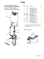
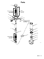
Parts
Part No. 222895 Pump, Series B
28:1 Ratio, with Quiet King Air Motor
Ref.
No.
Part No.
Description
Part No. 253377 Pump, Series A
28:1 Ratio, with Quiet King Air Motor
101
220106
AIR MOTOR, King, quiet
See 309348 for parts
Used on Model 222895 only
AIR MOTOR, King, quiet
See 309348 for parts
Used on Model 253377 only
ADAPTER, connecting rod
NUT, coupling
WRENCH, packing nut
PUMP, displacement
See pages 28 & 30 for parts
PUMP, displacement
See pages 28 & 30 for parts
NUT, hex; M16 x 2.0
ROD, tie; 265 mm (10.43 in.)
shoulder to shoulder
COLLAR, coupling
INTAKE AND EXHAUST KIT
Used on Model 253377 only
235525
102}
103}
104}
105
101
184451
184096
184278
222805
687055
102}
106}
107}
106166
184452
108}
109
184130
249967
Qty.
1
1
1
1
1
1
1
3
3
2
1
} These parts are included in Connection Kit 235414. For
applications requiring stainless steel tie rods, order Connection Kit 222913.
Detail of Model 253377
108}
103}
109
}107
105
}106
104}
TI7925A
0568C
308148
25
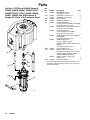
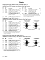
Parts
Part Nos. C59792 and 222939, Series B;
233069, 233070, 234667, 234824 241957,
243689 246923, 246924, 246989, 246990,
246991, 246992, and 253842 Series A
Pumps 45:1 Ratio, with Premier Air Motor
Ref.
No.
Part No.
Description
101
222800
102}
184582
617463
184096
184278
C59703
AIR MOTOR, Premier
See 308213 for parts
1
ADAPTER, connecting rod
1
ADAPTER, (234824 only)
1
NUT, coupling
1
WRENCH, packing nut
1
PUMP, displacement
(used on C59792, 233069, and 233070)
See pages 28 & 30 for parts
1
PUMP, displacement (used on 222939)
See pages 28 & 30 for parts
1
PUMP, displacement
(used on 241957 and 243689)
See pages 28 & 30 for parts
1
PUMP, displacement (used on 246923
and 246924)
See pages 28 & 30 for parts
1
PUMP, displacement
(used on 234667, 234824,
246989, 246990, 246991, 246992, and
253842)
See pages 28 & 30 for parts
1
NUT, hex; M16 x 2.0
3
ROD, tie; 380 mm (14.96 in.)
shoulder to shoulder (used on 222939,
C59792, 241957, 243689, 246989,
3
246990, 246991 and 246992)
ROD, tie 730.25 mm (28.75 in)
(234824 only)
3
COLLAR, coupling
2
103}
104
105
222805
241956
246925
249992
106}
107}
106166
184382
102}
101
617464
108}
} These parts are included in Connection Kit 235419. For
applications requiring stainless steel tie rods, order Connection Kit 235420.
108}
}107
103}
}106
105
104
01397C
26
308148
184130
Qty.
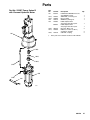
Parts
Part No. 222897 Pump, Series B
with Viscount Hydraulic Motor
Ref.
No.
101
Part No.
235345
102}
103}
104
105
184595
184096
184278
222805
687055
101
106}
107}
106166
184596
108}
184130
Description
HYDRAULIC MOTOR, Viscount,
See 308048 for parts
ADAPTER, connecting rod
NUT, coupling
WRENCH, packing nut
PUMP, displacement
See pages 28 & 30 for parts
PUMP, displacement
See pages 28 & 30 for parts
NUT, hex; M16 x 2.0
ROD, tie; 315 mm (12.40 in.)
shoulder to shoulder
COLLAR, coupling
Qty.
1
1
1
1
1
1
3
3
2
} These parts are included in Connection Kit 222976.
102}
108}
103}
}107
105
}106
104
0569C
308148
27
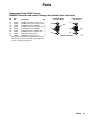
Parts
NOTE: The parts listed on this page are common to all
displacement pumps covered in this manual. The pumps use
different packing configurations. Standard Models 222805,
241956, 249992, and 687055 use stainless steel cap screws
with washers.
14
15
253742
16n
Ref
No.
Part
No.
1
184276
687118
15G852
3
4
184458
184387
15B316
5*
6*
7
109213
184072
184461
15G853
9
10n
184283
102973
112267
**
15C869
12
222795
253743
184282
222838
110294
C59027
Description
Qty
ROD, displacement; stainless steel
(used on 222796, 222805, 222988,
246925, 687055, C59703 and 246987) 1
ROD, displacement; ceramic
(used on 241956 and 246988)
1
ROD, displacement; sst
(used on 249992 only)
1
PACKING NUT/WET-CUP; SST
1
FITTING, outlet; 1–1/2 in. npt(m) x
M42 x 20; stainless steel
1
FITTING, outlet; 3/4 in. npt(m) x
M42 x 20; SST (used on 687055)
1
O-RING; PTFE
1
SEAL; acetal
2
CYLINDER; stainless steel
1
CYLINDER, sst
(used on 249992 only)
1
GUIDE, ball, piston; stainless steel
1
BALL, piston; stainless steel;
1.25 in. (31.8 mm) dia.
(used on 222805, 687055)
1
BALL, piston; tungsten;
1.25 in. (31.8 mm) dia.
(used on C59703, 241956 and
246925)
1
BALL, piston; silicone nitride;
1.25 in. (31.8 mm) dia.
(used on 246987, 246988 and 249992) 1
HOUSING, seat, piston valve;
stainless steel w/tungsten carbide seat 1
HOUSING, seat, piston valve
(used on 249992 only)
1
**
15C868
17
19
27*
34
184390
184389
102857
184392
35
190293
36
101748
GUIDE, ball, intake; stainless steel
1
HOUSING, seat, intake valve;
stainless steel w/tungsten carbide seat 1
HOUSING, seat, intake valve
(used on 249992 only)
1
BALL, intake; stainless steel;
2 in. (50.8 mm) dia.
1
BALL, intake; carbide;
2 in. (50.8 mm) dia.
(used on C59703, 241956 and
246925)
1
BALL, intake; silicone nitride;
2 in. (50.8 mm) dia.
(used on 246987, 246988 and 249992) 1
HOUSING, intake; stainless steel
1
HOUSING, outlet, pump
1
O-RING; PTFE
1
HOUSING, valve; 3/8–18 npt x 1/2–20
unf-2b (not used on 249992)
1
PLUG, valve; 1/2–20 unf-2a
(not used on 249992)
1
PLUG, pipe, sst
(Replaces both 34 and 35 on 246987,
246988 and 249992)
1
* These parts are included in Packing Repair Kit 222845,
which may be purchased separately for Displacement
Pumps 222805, 241956, and 687055. They are also included in the packing conversion kits described on pages
30 and 32.
** Included with Packing Repair Kit 249098.
n Keep these spare parts on hand to reduce down time.
02257
28
308148
Parts
3
Throat Packings
(see pages
30 and 32)
20, 33
(see pages
30 and 32)
19
*5
34
35
4
36
Replaces 34 and 35
on 246987, 246988,
and 249992)
1
7
9
6*
14
10n
16n
6*
Piston Packings
(see pages
30 and 32)
15
27*
17
12
02257
308148
29
Parts
Displacement Pumps 222805, 241956, and 687055, Series A
(UHMWPE and PTFE Packings, with Stainless Steel Cap Screws)
Ref
No.
Part
No.
11*
13*
18*
20
184232
184182
109262
109470
25*
184181
Description
Qty
GLAND, male; piston; stainless steel
GLAND, female; piston; stainless steel
V-PACKING; piston; UHMWPE
SCREW, cap, hex hd; 5/8–11 unc–2A
x 12 in. (305 mm); stainless steel;
Used on Models 222805, 241956, and
687055; see page 29.
1
1
3
6
GLAND, female; throat; stainless steel 1
Ref
No.
Part
No.
26*
28*
109261
109312
687057
Description
Qty
V-PACKING; throat; UHMWPE
3
V-PACKING; piston; PTFE
2
PACKING; graphite; PTFE
Used on Model 687055
2
29*
184231
GLAND, male; throat; stainless steel 1
30*
109311
V–PACKING; throat; PTFE
2
* These parts are included in Packing Repair Kit 222845,
which may be purchased separately. For packing conversion kits, see pages 30 through 32.
Displacement Pump 246925, Series A
(UHMWPE and Leather Packings, with Stainless Steel Cap Screws)
Ref
No.
Part
No.
11*
13*
18*
20
184232
184182
109262
109470
25*
26*
28*
29*
30*
33
184181
109261
184312
184231
184311
184618
Description
Qty
GLAND, male; piston; stainless steel
GLAND, female; piston; stainless steel
V-PACKING; piston; UHMWPE
SCREW, cap, hex hd; 5/8–11 unc–2A
x 12 in. (305 mm); stainless steel
GLAND, female; throat; stainless steel
V-PACKING; throat; UHMWPE
V-PACKING; piston; leather
GLAND, male; throat; stainless steel
V-PACKING; throat; leather
WASHER, flat; stainless steel;
1
1
3
6
1
3
2
1
2
6
THROAT PACKINGS:
LIPS FACE DOWN
*25
*26
PISTON PACKINGS:
LIPS FACE UP
*11
30*
*29
*18
28*
*13
LUBRICATE PACKINGS
0805
0806
* These parts are included in Repair Kit 222848, which may
be purchased separately. For packing conversion kits,
see pages 30 through 32.
Displacement Pump 246987 and 246988, Series A
(UHMWPE and Leather Packings, with Stainless Steel Cap Screws)
Ref
No.
Part
No.
11*
13*
18*
20
184232
184182
109262
109470
25*
26*
28*
29*
30*
33
184181
109261
184312
184231
184311
184618
Description
Qty
GLAND, male; piston; stainless steel
GLAND, female; piston; stainless steel
V-PACKING; piston; UHMWPE
SCREW, cap, hex hd; 5/8–11 unc–2A
x 12 in. (305 mm); stainless steel
GLAND, female; throat; stainless steel
V-PACKING; throat; UHMWPE
V-PACKING; piston; leather
GLAND, male; throat; stainless steel
V-PACKING; throat; leather
WASHER, flat; stainless steel;
1
1
3
6
1
3
2
1
4
6
* These parts are included in Packing Repair Kit 222850,
which may be purchased separately. For packing conversion kits, see pages 30 through page 32.
30
308148
THROAT PACKINGS:
LIPS FACE DOWN
*25
*26
*29
PISTON PACKINGS:
LIPS FACE UP
*11
30*
*18
28*
*13
LUBRICATE PACKINGS
0805
0806
Parts
Displacement Pump 249992, Series A
(UHMWPE Submicron and Leather Packings, with Stainless Steel Cap Screws)
Ref
No.
Part
No.
Description
Qty
11*
184232
GLAND, male; piston; stainless steel 1
13*
184182
GLAND, female; piston; stainless steel 1
18*
109262
V–PACKING; piston; UHMWPE
3
25*
184181
GLAND, female; throat; stainless steel 1
26*
109261
V–PACKING; piston; UHMWPE
3
28*
120533
V-PACKING; piston; UHMWPE S/M
2
29*
184231
GLAND, male; throat; stainless steel 1
30*
184311
V-PACKING; throat; leather
4
33
184618
WASHER, flat; stainless steel
6
* These parts are included in Packing Repair Kit 253744,
which may be purchased separately. For packing conversion kits, see pages 30 through 32.
THROAT PACKINGS:
LIPS FACE DOWN
PISTON PACKINGS:
LIPS FACE UP
*11
*25
30*
*32
*31
*29
*13
LUBRICATE PACKINGS
28*
0805
0806
308148
31
Parts
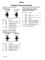
Packing Conversion Kits
Packing Conversion Kit 222846,
(PTFE Packings)
THROAT PACKINGS:
LIPS FACE DOWN
PISTON PACKINGS:
LIPS FACE UP
*11
*25
*30
*28
*29
*13
LUBRICATE PACKINGS
Ref
No.
Part
No.
11*
13*
25*
28*
184232
184182
184181
109312
687057
29*
30*
184231
109311
687056
Max–Life Conversion Kit 288551, Series A
Includes parts to convert existing
Dura–Flo 1800 (246987) to Max–Life
Displacement Pump 249992.
Description
Ref
No.
Qty
1
1
1
5
5
1
5
5
Packing Conversion Kit 222848,
(UHMWPE and Leather Packings)
THROAT PACKINGS:
LIPS FACE DOWN
*25
*26
PISTON PACKINGS:
LIPS FACE UP
*11
32*
*29
*18
31*
*13
LUBRICATE PACKINGS
0805
0806
Ref
No.
Part
No.
Description
11*
13*
18*
25*
26*
29*
31*
32*
184232
184182
109262
184181
109261
184231
184312
184311
GLAND, male; piston; stainless steel
GLAND, female; piston; stainless steel
V-PACKING; piston; UHMWPE
GLAND, female; throat; stainless steel
V-PACKING; throat; UHMWPE
GLAND, male; throat; stainless steel
V-PACKING; piston; leather
V-PACKING; throat; leather
32
308148
Description
1
7
11*
12
13*
15
0805
0806
GLAND, male; piston; stainless steel
GLAND, female; piston; stainless steel
GLAND, female; throat; stainless steel
V-PACKING; piston; PTFE
PACKING; graphite; PTFE
Used on Model 687055
GLAND, male; throat; stainless steel
V-PACKING; throat; PTFE
PACKING; graphite; PTFE
Used on Model 687055
Part
No.
Qty
1
1
3
1
3
1
2
2
Qty
15G852
Rod
15G853
Cylinder
184232
GLAND, male; piston; stainless steel
253743
Housing
184182
GLAND, female; piston; stainless steel
253742
Housing
253744
Seals Kit
18*
109262
V–PACKING; piston; UHMWPE
25*
184181
GLAND, female; throat; stainless steel
26*
109261
V–PACKING; piston; UHMWPE
28*
120533
V-PACKING; piston; UHMWPE S/M
29*
184231
GLAND, male; throat; stainless steel
30*
184311
V-PACKING; throat; leather
* These parts are included in Packing Repair Kit 253744,
which may be purchased separately.
Refer to page 29 for assembly detail.
1
1
1
1
1
1
3
1
3
2
1
4
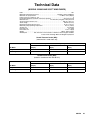
Technical Data
(MODELS 222895 AND 253377 KING PUMPS)
Ratio . . . . . . . . . . . . . . . . . . . . . . . . . . . . . . . . . . . . . . . . . . . . . . . . . . . . . . . . . . . . . . . . . . . . . . . 28:1
Maximum fluid working pressure . . . . . . . . . . . . . . . . . . . . . . . . . . 19.3 MPa, 193 bar (2800 psi)
Maximum air input pressure . . . . . . . . . . . . . . . . . . . . . . . . . . . . . . . . . . 0.7 MPa, 7 bar (100 psi)
Pump cycles per 3.8 liters (1 gal.) . . . . . . . . . . . . . . . . . . . . . . . . . . . . . . . . . . . . . . . . . . . . . . . . . 9
Recommended pump speed for continuous operation . . . . . . . . . . . . . . . . . . 50 cycles per min
Maximum flow . . . . . . . . . . . . . . . . . . . . . . . . . . . . . . . 21.8 liters/min (5.8 gpm) at 50 cycles/min
Air motor piston effective area . . . . . . . . . . . . . . . . . . . . . . . . . . . . . . . . . . . . . 506 cm@ (78.5 in.@)
Stroke length . . . . . . . . . . . . . . . . . . . . . . . . . . . . . . . . . . . . . . . . . . . . . . . . . . . . . 120 mm (4.75 in.)
Displacement pump effective area . . . . . . . . . . . . . . . . . . . . . . . . . . . . . . . . . . . 18 cm@ (2.79 in.@)
Maximum pump operating temperature . . . . . . . . . . . . . . . . . . . . . . . . . . . . . . . . 65.5_C (150_F)
Air inlet size . . . . . . . . . . . . . . . . . . . . . . . . . . . . . . . . . . . . . . . . . . . . . . . . . . . . . . . . . . . 3/4 npsm(f)
Fluid inlet size . . . . . . . . . . . . . . . . . . . . . . . . . . . . . . . . . . . . . . . . . . . . . . . . . . . . . . . . . . 2 in. npt(f)
Fluid outlet size . . . . . . . . . . . . . . . . . . . . . . . . . . . . . . . . . . . . . . . . . . . . . . . . . . . . 1–1/2 in. npt(m)
Weight . . . . . . . . . . . . . . . . . . . . . . . . . . . . . . . . . . . . . . . . . . . . . . . . . . . . . . approx. 69 kg (152 lb)
Wetted parts . . . . . . . . . 304, 329 and 17–4 PH Grades of Stainless Steel; Tungsten Carbide;
acetal; PTFE; Ultra-High Molecular Weight Polyethylene
Sound Pressure Levels (dBa)
(measured at 1 meter from unit)
Input Air Pressures at 15 cycles per minute
Air Motor
0.28 MPa, 2.8 bar
(40 psi)
0.48 MPa, 4.8 bar
(70 psi)
0.63 MPa, 6.3 bar
(90 psi)
King
78.8
82.7
90.5
Quiet King
77.9
79.2
87.5
Sound Power Levels (dBa)
(tested in accordance with ISO 9614–2)
Input Air Pressures at 15 cycles per minute
Air Motor
0.28 MPa, 2.8 bar
(40 psi)
0.48 MPa, 4.8 bar
(70 psi)
0.63 MPa, 6.3 bar
(90 psi)
King
86.5
88.8
97.7
Quiet King
85.2
86.6
95.2
308148
33
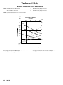
Technical Data
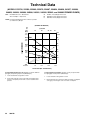
(MODELS 222895 AND 253377 KING PUMPS)
KEY:
Fluid Outlet Pressure – Black Curves
Air Consumption – Gray Curves
A
B
C
0.63 MPa, 6.3 bar (90 psi) Air Pressure
0.49 MPa, 4.9 bar (70 psi) Air Pressure
0.28 MPa, 2.8 bar (40 psi) Air Pressure
NOTE: Recommended pump speed for continuous operation
(to shaded area): 50 cpm
MODEL 222895
(QUIET KING AIR MOTOR)
psi
bar
MPa
18
2500
175
17.5
cycles/min
36
54
72
scfm
m#/min
250
7.00
A
200
5.60
2000
140
14.0
B
150
4.20
A
1500
105
10.5
B
1000
70
7.0
100
2.80
C
C
50
1.40
500
35
3.5
0
gpm 0
liters/min
2
7.6
4
15.2
6
22.8
8
30.4
FLUID FLOW (NO. 10 WEIGHT OIL)
To find Pump Air Consumption (m#/min or scfm) at a specific fluid
flow (lpm/gpm) and air pressure (MPa/bar/psi):
1. Locate desired flow along bottom of chart.
34
308148
2. Read vertical line up to intersection with selected air consumption
curve (gray). Follow right to scale to read air consumption.
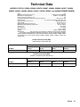
Technical Data
(MODELS C59792, 222939, 233069, 233070, 234667, 234824, 234826, 241957, 243689,
246923, 246924, 246989, 246990, 246991, 246992, 253842, and 249992 PREMIER PUMPS)
Ratio . . . . . . . . . . . . . . . . . . . . . . . . . . . . . . . . . . . . . . . . . . . . . . . . . . . . . . . . . . . . . . . . . . . . . . . 45:1
Maximum fluid working pressure . . . . . . . . . . . . . . . . . . . . . . . . . . . 31 MPa, 310 bar (4500 psi)
Maximum air input pressure . . . . . . . . . . . . . . . . . . . . . . . . . . . . . . . . . . 0.7 MPa, 7 bar (100 psi)
Pump cycles per 3.8 liters (1 gal.) . . . . . . . . . . . . . . . . . . . . . . . . . . . . . . . . . . . . . . . . . . . . . . . . 8.7
Recommended pump speed for continuous operation . . . . . . . . . . . . . . . . . . 60 cycles per min
Maximum flow . . . . . . . . . . . . . . . . . . . . . . . . . . . . . . . . 26.1 liters/min (6.9 gpm) at 60 cycles/min
Air motor piston effective area . . . . . . . . . . . . . . . . . . . . . . . . . . . . . . . . . . . . . 800 cm@ (38.5 in.@)
Stroke length . . . . . . . . . . . . . . . . . . . . . . . . . . . . . . . . . . . . . . . . . . . . . . . . . . . . . 120 mm (4.75 in.)
Displacement pump effective area . . . . . . . . . . . . . . . . . . . . . . . . . . . . . . . . . . . 18 cm@ (2.79 in.@)
Maximum pump operating temperature . . . . . . . . . . . . . . . . . . . . . . . . . . . . . . . . 65.5_C (150_F)
Air inlet size . . . . . . . . . . . . . . . . . . . . . . . . . . . . . . . . . . . . . . . . . . . . . . . . . . . . . . . . . . . 3/4 npsm(f)
Fluid inlet size . . . . . . . . . . . . . . . . . . . . . . . . . . . . . . . . . . . . . . . . . . . . . . . . . . . . . . . . . . . 2 in. npt(f)
Fluid outlet size . . . . . . . . . . . . . . . . . . . . . . . . . . . . . . . . . . . . . . . . . . . . . . . . . . . . . 1–1/2 in. npt(m)
Weight . . . . . . . . . . . . . . . . . . . . . . . . . . . . . . . . . . . . . . . . . . . . . . . . . . . . . approx. 109 kg (240 lb)
Wetted parts . . . . . . . . . 304, 329 and 17–4 PH Grades of Stainless Steel; Tungsten Carbide;
acetal; PTFE; Ultra-High Molecular Weight Polyethylene; Ceramic (model 241957, 246991,
246992, 233069 and 233070 only); leather (models 246923, 246924, 246989, 246990, 246991
and 246992 only); silicon nitride (models 246989, 246990, 246991, 246992, 234824 and
253842 only)
Sound Pressure Levels (dBa)
(measured at 1 meter from unit)
Input Air Pressures at 15 cycles per minute
Air Motor
0.28 MPa, 2.8 bar
(40 psi)
0.48 MPa, 4.8 bar
(70 psi)
0.63 MPa, 6.3 bar
(90 psi)
0.7 MPa, 7 bar
(100 psi)
Premier
82.5
82.4
83.2
83.0
Sound Power Levels (dBa)
(tested in accordance with ISO 9614–2)
Input Air Pressures at 15 cycles per minute
Air Motor
0.28 MPa, 2.8 bar
(40 psi)
0.48 MPa, 4.8 bar
(70 psi)
0.63 MPa, 6.3 bar
(90 psi)
0.7 MPa, 7 bar
(100 psi)
Premier
90.6
90.6
93.0
95.9
308148
35
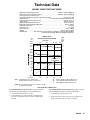
Technical Data
(MODELS C59792, 222939, 233069, 233070, 234667, 234824, 234826, 241957, 243689,
246923, 246924, 246989, 246990, 246991, 246992, 253842, and 249992 PREMIER PUMPS)
KEY:
Fluid Outlet Pressure – Black Curves
Air Consumption – Gray Curves
A
B
C
0.7 MPa, 7 bar (100 psi) Air Pressure
0.49 MPa, 4.9 bar (70 psi) Air Pressure
0.28 MPa, 2.8 bar (40 psi) Air Pressure
NOTE: Recommended pump speed for continuous operation
(to shaded area): 60 cpm
(PREMIER AIR MOTORS)
psi
bar
MPa
5000
350
35.0
4000
280
28.0
3000
210
21.0
2000
140
14.0
18
cycles/min
36
54 60
72
scfm
m#/min
400
11.20
A
300
8.40
B
A
B
200
5.60
C
1000
70
7.0
C
100
2.80
0
gpm 0
liters/min
2
7.6
4
15.2
6
22.8
8
30.4
FLUID FLOW (NO. 10 WEIGHT OIL)
To find Fluid Outlet Pressure (MPa/bar/psi) at a specific fluid flow
(lpm/gpm) and operating air pressure (MPa/bar/psi):
1. Locate desired flow along bottom of chart.
2. Follow vertical line up to intersection with selected fluid outlet
pressure curve (black). Follow left to scale to read fluid outlet
pressure.
36
308148
To find Pump Air Consumption (m#/min or scfm) at a specific fluid
flow (lpm/gpm) and air pressure (MPa/bar/psi):
1. Locate desired flow along bottom of chart.
2. Read vertical line up to intersection with selected air consumption
curve (gray). Follow right to scale to read air consumption.
Technical Data
(MODEL 222897 VISCOUNT PUMP)
Maximum fluid working pressure . . . . . . . . . . . . . . . . . . . . . . . . . . . 18 MPa, 179 bar (2600 psi)
Maximum hydraulic oil input pressure . . . . . . . . . . . . . . . . . . . . . . . 10 MPa, 103 bar (1500 psi)
Pump cycles per 3.8 liters (1 gal.) . . . . . . . . . . . . . . . . . . . . . . . . . . . . . . . . . . . . . . . . . . . . . . . . . 9
Recommended pump speed for continuous operation . . . . . . . . . . . . . . . . . . 60 cycles per min
Maximum flow . . . . . . . . . . . . . . . . . . . . . . . . . . . . . . . 26.1 liters/min (6.9 gpm) at 60 cycles/min
Hydraulic motor piston effective area . . . . . . . . . . . . . . . . . . . . . . . . . . . . . . . 31.6 cm@ (4.9 in.@)
Stroke length . . . . . . . . . . . . . . . . . . . . . . . . . . . . . . . . . . . . . . . . . . . . . . . . . . . . . 120 mm (4.75 in.)
Displacement pump effective area . . . . . . . . . . . . . . . . . . . . . . . . . . . . . . . . . . . 18 cm@ (2.79 in.@)
Maximum pump operating temperature . . . . . . . . . . . . . . . . . . . . . . . . . . . . . . . . 65.5_C (150_F)
Hydraulic oil inlet size . . . . . . . . . . . . . . . . . . . . . . . . . . . . . . . . . . . . . . . . . . . . . . . . . . . . 3/4 npt(f)
Fluid inlet size . . . . . . . . . . . . . . . . . . . . . . . . . . . . . . . . . . . . . . . . . . . . . . . . . . . . . . . . . . 2 in. npt(f)
Fluid outlet size . . . . . . . . . . . . . . . . . . . . . . . . . . . . . . . . . . . . . . . . . . . . . . . . . . . . . 1-1/2 in. npt(m)
Weight . . . . . . . . . . . . . . . . . . . . . . . . . . . . . . . . . . . . . . . . . . . . . . . . . . . . . . approx. 89 kg (196 lb)
Wetted parts . . . . . . . . . 304, 329 and 17–4 PH Grades of Stainless Steel; Tungsten Carbide;
acetal; PTFE; Ultra-High Molecular Weight Polyethylene
MODEL 222897
(VISCOUNT HYDRAULIC MOTOR)
psi
bar
MPa
2500
175
17.5
18
cycles/min
36
54
60
A
gpm
lpm
(hyd.
72 oil)
25
95.0
20
76.0
2000
140
14.0
B
15
57.0
1500
105
10.5
1000
70
7.0
hydraulic oil
consumption
C
10
38.0
5
19.0
500
35
3.5
0
gpm 0
liters/min
KEY:
2
7.6
4
15.2
Fluid Outlet Pressure – Black Curves
Hydraulic Oil Consumption – Gray Curves
6
22.8
A
B
C
8
30.4
105 bar (1500 psi) Hydraulic Oil Pressure
74 bar (1050 psi) Hydraulic Oil Pressure
42 bar (600 psi) Hydraulic Oil Pressure
NOTE: Recommended pump speed for continuous operation
(to shaded area): 60 cpm
FLUID FLOW (NO. 10 WEIGHT OIL)
To find Fluid Outlet Pressure (MPa/bar/psi) at a specific fluid flow
(lpm/gpm) and operating hydraulic oil pressure (MPa/bar/psi):
1. Locate desired flow along bottom of chart.
2. Follow vertical line up to intersection with selected fluid outlet
pressure curve (black). Follow left to scale to read fluid outlet
pressure.
To find Pump Hydraulic Oil Consumption (lpm or gpm) at a specific
fluid flow (lpm/gpm) and hydraulic oil pressure (MPa/bar/psi):
1. Locate desired flow along bottom of chart.
2. Read vertical line up to intersection with oil consumption curve
(gray). Follow right to scale to read oil consumption.
308148
37
Dimensions
Model 222895 Shown
C
A
B
D
0566
Pump Model
A
B
C
D
222895, 253377
1235.1 mm (48.63 in.)
642.6 mm (25.3 in.)
592.5 mm (23.33 in.)
298.0 mm (11.73 in.)
C59792,
222939,233069,
233070, 234667,
241947, 243689,
246989, 246990,
246991, 246992,
246923, 246924,
249992
1160.0 mm (45.7 in.)
759.0 mm (29.9 in.)
401.0 mm (15.79 in.)
413.0 mm (16.3 in.)
222897
1264.8 mm (49.8 in.)
642.6 mm (25.3 in.)
622.2 mm (24.5 in.)
298.0 mm (11.73 in.)
234824
1405.0 mm (55.3 in.)
887.6 mm (34.9 in.)
867.6 mm (34.16 in.)
543.0 mm (21.38 in.)
38
308148
Mounting Hole Layouts
King, Bulldog, and Viscount Pumps
94.28 mm
(3.712 in.)
101.6 mm
(4.0 in.)
94.28 mm
(3.712 in.)
50.8 mm
(2.0 in.)
11.1 mm
(0.437 in.)
DIA (4)
88 mm
(3.464 in.)
0653
Premier Pumps
135.0 mm
(5.3 in.)
67.5 mm
(2.7 in.)
116.9 mm
(4.6 in.)
87.9 mm
(3.5 in.)
Three M16 x 2.0 Holes
Three 3/8–16 Mounting Studs
101.5 mm
(4.0 in.)
50.7 mm
(2.0 in.)
06555
308148
39
Graco Standard Warranty
Graco warrants all equipment manufactured by Graco and bearing its name to be free from defects in material and workmanship on the
date of sale to the original purchaser for use. With the exception of any special, extended, or limited warranty published by Graco,
Graco will, for a period of twelve months from the date of sale, repair or replace any part of the equipment determined by Graco to be
defective. This warranty applies only when the equipment is installed, operated and maintained in accordance with Graco’s written
recommendations.
This warranty does not cover, and Graco shall not be liable for general wear and tear, or any malfunction, damage or wear caused by
faulty installation, misapplication, abrasion, corrosion, inadequate or improper maintenance, negligence, accident, tampering, or substitution of non–Graco component parts. Nor shall Graco be liable for malfunction, damage or wear caused by the incompatibility of
Graco equipment with structures, accessories, equipment or materials not supplied by Graco, or the improper design, manufacture,
installation, operation or maintenance of structures, accessories, equipment or materials not supplied by Graco.
This warranty is conditioned upon the prepaid return of the equipment claimed to be defective to an authorized Graco distributor for
verification of the claimed defect. If the claimed defect is verified, Graco will repair or replace free of charge any defective parts. The
equipment will be returned to the original purchaser transportation prepaid. If inspection of the equipment does not disclose any defect
in material or workmanship, repairs will be made at a reasonable charge, which charges may include the costs of parts, labor, and
transportation.
THIS WARRANTY IS EXCLUSIVE, AND IS IN LIEU OF ANY OTHER WARRANTIES, EXPRESS OR IMPLIED, INCLUDING BUT
NOT LIMITED TO WARRANTY OF MERCHANTABILITY OR WARRANTY OF FITNESS FOR A PARTICULAR PURPOSE.
Graco’s sole obligation and buyer’s sole remedy for any breach of warranty shall be as set forth above. The buyer agrees that no other
remedy (including, but not limited to, incidental or consequential damages for lost profits, lost sales, injury to person or property, or any
other incidental or consequential loss) shall be available. Any action for breach of warranty must be brought within two (2) years of the
date of sale.
Graco makes no warranty, and disclaims all implied warranties of merchantability and fitness for a particular purpose in connection
with accessories, equipment, materials or components sold but not manufactured by Graco. These items sold, but not manufactured
by Graco (such as electric motors, switches, hose, etc.), are subject to the warranty, if any, of their manufacturer. Graco will provide
purchaser with reasonable assistance in making any claim for breach of these warranties.
In no event will Graco be liable for indirect, incidental, special or consequential damages resulting from Graco supplying equipment
hereunder, or the furnishing, performance, or use of any products or other goods sold hereto, whether due to a breach of contract,
breach of warranty, the negligence of Graco, or otherwise.
FOR GRACO CANADA CUSTOMERS
The parties acknowledge that they have required that the present document, as well as all documents, notices and legal proceedings
entered into, given or instituted pursuant hereto or relating directly or indirectly hereto, be drawn up in English. Les parties reconnaissent avoir convenu que la rédaction du présente document sera en Anglais, ainsi que tous documents, avis et procédures judiciaires
exécutés, donnés ou intentés à la suite de ou en rapport, directement ou indirectement, avec les procedures concernées.
Graco Information
For the latest information about Graco products, visit www.graco.com.
TO PLACE AN ORDER, contact your Graco distributor or call to identify the distributor closest to you:
Phone: 612–623–6921 or Toll Free: 1–800–328–0211 Fax: 612–378–3505
All written and visual data contained in this document reflects the latest product information available at the time of publication.
Graco reserves the right to make changes at any time without notice.
Original instructions. This manual contains English. MM 308148
Graco Headquarters: Minneapolis
International Offices: Belgium, China, Japan, Korea
GRACO INC. P.O. BOX 1441 MINNEAPOLIS, MN 55440–1441
Copyright 1992, Graco Inc. is registered to ISO 9001
www.graco.com
Revised 02/2010
40
308148