1
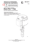
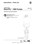
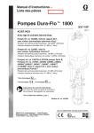
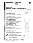
Instructions – Parts List
45:1 RATIO PREMIERt CARBON STEEL
Cart-Mounted Airless Package
WITH DURA-FLOt 1800 DISPLACEMENT PUMP
308215L
315 bar, 31.5 MPa (4500 psi) Maximum Working Pressure
7 bar, 0.7 MPa (100 psi) Maximum Air Inlet Pressure
Part No. 222973, Series B
With High Pressure Fluid Filter
Part No. 238144, Series B
With High Pressure
Fluid Filter, hose and gun
05915
Important Safety Instructions
Read all warnings and instructions in this manual.
Save these instructions.
GRACO INC. P.O. BOX 1441 MINNEAPOLIS, MN 55440–1441
Copyright 1993, Graco Inc. is registered to I.S. EN ISO 9001
Model 238144 Shown
Table of Contents
Warnings . . . . . . . . . . . . . . . . . . . . . . . . . . . . . . . . . . . . . . 2
Setup . . . . . . . . . . . . . . . . . . . . . . . . . . . . . . . . . . . . . . . . . 6
Operation . . . . . . . . . . . . . . . . . . . . . . . . . . . . . . . . . . . . . 8
Parts . . . . . . . . . . . . . . . . . . . . . . . . . . . . . . . . . . . . . . . . 12
Technical Data . . . . . . . . . . . . . . . . . . . . . . . . . . . . . . . . 14
Dimensions . . . . . . . . . . . . . . . . . . . . . . . . . . . . . . . . . . . 15
Graco Standard Warranty . . . . . . . . . . . . . . . . . . . . . . 16
Graco Information . . . . . . . . . . . . . . . . . . . . . . . . . . . . . 16
Symbols
Warning Symbol
WARNING
This symbol alerts you to the possibility of serious
injury or death if you do not follow the instructions.
Caution Symbol
CAUTION
This symbol alerts you to the possibility of damage to
or destruction of equipment if you do not follow the
instructions.
WARNING
EQUIPMENT MISUSE HAZARD
Equipment misuse can cause the equipment to rupture or malfunction and result in serious injury.
INSTRUCTIONS
D This equipment is for professional use only.
D Read all instruction manuals, tags, and labels before operating the equipment.
D Use the equipment only for its intended purpose. If you are not sure, call your Graco distributor.
D Do not alter or modify this equipment.
D Check equipment daily. Repair or replace worn or damaged parts immediately.
D Do not exceed the maximum working pressure of the lowest rated system component. Refer to the
Technical Data on page 14 for the maximum working pressure of this equipment.
D Use fluids and solvents which are compatible with the equipment wetted parts. Refer to the Technical Data section of all equipment manuals. Read the fluid and solvent manufacturer’s warnings.
D Do not use hoses to pull equipment.
D Route hoses away from traffic areas, sharp edges, moving parts, and hot surfaces. Do not expose
Graco hoses to temperatures above 82_C (180_F) or below –40_C (–40_F).
D Wear hearing protection when operating this equipment.
D Do not lift pressurized equipment.
D Comply with all applicable local, state, and national fire, electrical, and safety regulations.
2
308215
WARNING
SKIN INJECTION HAZARD
Spray from the gun, leaks or ruptured components can inject fluid into your body and cause extremely
serious injury, including the need for amputation. Fluid splashed in the eyes or on the skin can also
cause serious injury.
D Fluid injected into the skin might look like just a cut, but it is a serious injury. Get immediate surgical treatment.
D Do not point the gun at anyone or at any part of the body.
D Do not put your hand or fingers over the spray tip.
D Do not stop or deflect leaks with your hand, body, glove or rag.
D Do not “blow back” fluid; this is not an air spray system.
D Always have the tip guard and the trigger guard on the gun when spraying.
D Check the gun diffuser operation weekly. Refer to the gun manual.
D Be sure the gun trigger safety operates before spraying.
D Lock the gun trigger safety when you stop spraying.
D Follow the Pressure Relief Procedure on page 8 if the spray tip clogs and before cleaning,
checking or servicing the equipment.
D Tighten all fluid connections before operating the equipment.
D Check the hoses, tubes, and couplings daily. Replace worn or damaged parts immediately.
Do not repair high pressure couplings; you must replace the entire hose.
D Fluid hoses must have spring guards on both ends, to help protect them from rupture caused by
kinks or bends near the couplings.
MOVING PARTS HAZARD
Moving parts, such as the air motor rocker arms, can pinch or amputate your fingers.
D Keep clear of all moving parts when starting or operating the pump.
D Before servicing the equipment, follow the Pressure Relief Procedure on page 8 to prevent the
equipment from starting unexpectedly.
308215
3
WARNING
FIRE AND EXPLOSION HAZARD
Improper grounding, poor ventilation, open flames or sparks can cause a hazardous condition and
result in a fire or explosion and serious injury.
D Ground the equipment and the object being sprayed. Refer to Grounding on page 5.
D If there is any static sparking or you feel an electric shock while using this equipment, stop spraying immediately. Do not use the equipment until you identify and correct the problem.
D Provide fresh air ventilation to avoid the buildup of flammable fumes from solvents or the fluid
being sprayed.
D Keep the spray area free of debris, including solvent, rags, and gasoline.
D Electrically disconnect all equipment in the spray area.
D Extinguish all open flames or pilot lights in the spray area.
D Do not smoke in the spray area.
D Do not turn on or off any light switch in the spray area while operating or if fumes are present.
D Do not operate a gasoline engine in the spray area.
TOXIC FLUID HAZARD
Hazardous fluid or toxic fumes can cause serious injury or death if splashed in the eyes or on the skin,
inhaled, or swallowed.
D Know the specific hazards of the fluid you are using.
D Store hazardous fluid in an approved container. Dispose of hazardous fluid according to all local,
state and national guidelines.
D Always wear protective eyewear, gloves, clothing and respirator as recommended by the fluid and
solvent manufacturer.
4
308215
Setup
General Information
Grounding
NOTE: Reference numbers and letters in parentheses
in the text refer to the callouts in the figures and the
parts drawing.
NOTE: Always use Genuine Graco Parts and Accessories, available from your Graco distributor. Refer to
the Product Data Sheet for your pump, Form No.
305756. If you supply your own accessories, be sure
they are adequately sized and pressure rated for your
system.
Fig. 2 is only a guide for selecting and installing system components and accessories. Contact your Graco
distributor for assistance in designing a system to suit
your particular needs.
WARNING
FIRE AND EXPLOSION HAZARD
Before operating the pump, ground the
system as explained below. Also read
the section FIRE OR EXPLOSION HAZARD on page 4.
1. Pump: use the ground wire and clamp (supplied).
See Fig. 1. Loosen the grounding lug locknut (W)
and washer (X). Insert one end of the ground wire
(57) into the slot in lug (Z) and tighten the locknut
securely. Connect the other end of the wire to a
true earth ground.
W
Prepare the Operator
X
57
All persons who operate the equipment must be
trained in the safe, efficient operation of all system
components as well as the proper handling of all fluids.
All operators must thoroughly read all instruction
manuals, tags, and labels before operating the equipment.
Z
0864
Prepare the Site
Fig. 1
The Premier pumps require 6.4 m#/min (230 scfm) of
compressed air while operating at 7 bar (100 psi) air
pressure and 60 cycles per minute. Ensure that you
have an adequate compressed air supply.
2. Air and fluid hoses: use only electrically conductive
hoses.
Refer to Fig. 2. Bring a compressed air supply line (A)
from the air compressor to the pump location. Be sure
all air hoses (A) are properly sized and pressure-rated
for your system. Use only electrically conductive
hoses. The air hose should have a 3/4 npt(m) thread.
4. Spray gun: ground through connection to a properly grounded fluid hose and pump.
3. Air compressor: follow manufacturer’s recommendations.
5. Fluid supply container: follow your local code.
6. Object being sprayed: follow your local code.
Install a bleed-type shutoff valve (B) in the air line to
isolate the air line components for servicing. Install an
air line moisture trap and drain valve (C) to help remove moisture from the compressed air supply.
Keep the site clear of any obstacles or debris that
could interfere with the operator’s movement.
Have a grounded, metal pail available for use when
flushing the system or draining the fluid filter.
7. Solvent pails used when flushing: follow your local
code. Use only metal pails, which are conductive,
placed on a grounded surface. Do not place the
pail on a nonconductive surface, such as paper or
cardboard, which interrupts the grounding continuity.
8. To maintain grounding continuity when flushing or
relieving pressure, hold a metal part of the spray
gun firmly to the side of a grounded metal pail,
then trigger the gun.
308215
5
Setup
Supplied Components
D The suction hose (12) and tube (13) allow the
pump to draw fluid from a fluid container.
Refer to Fig. 2.
WARNING
A red-handled bleed-type master air valve (50) and
a fluid drain valve (D) are supplied. These accessories help reduce the risk of serious injury, including
fluid injection and splashing of fluid in the eyes or
on the skin, and injury from moving parts if you are
adjusting or repairing the pump.
The bleed-type master air valve relieves air trapped
between this valve and the pump after the valve is
closed. Trapped air can cause the pump to cycle
unexpectedly. Locate the valve close to the pump.
The fluid drain valve assists in relieving fluid pressure in the displacement pump, hose, and gun.
Triggering the gun to relieve pressure may not be
sufficient.
D The red-handled bleed-type master air valve
(50) is required in your system to relieve air trapped
between it and the air motor when the valve is
closed (see the WARNING above). Be sure the
bleed valve is easily accessible from the pump, and
is located downstream from the air regulator (33).
D With a wrench, loosen and remove the female air
line coupler (69). Screw it onto the main air hose
(A). Leave the mating coupler (68) attached to the
air manifold (46)
D The air regulator (33) controls pump speed and
outlet pressure by adjusting the air pressure to the
pump. Locate the regulator close to the pump, but
upstream from the bleed-type master air valve.
D Two fluid shutoff valves (67) are supplied at the
fluid filter outlets. Attach the fluid hose (103) to one
of the valves. Keep the other valve capped and
closed at all times unless you are using a second
hose and gun.
Connect the Suction Hose
Apply thread sealant to the suction hose (12) and
screw it into the bushing (8) at the pump’s fluid intake.
Screw the elbow (14) onto the other end of the hose,
and screw the suction tube (24) into the elbow.
Connect the Fluid Hoses and Gun
NOTE: Model 238144 includes a Hose and Gun Kit
(101), which supplies fluid hoses, a spray gun, and
connecting parts (ref. nos. 102–106). If you supply
your own fluid hoses and gun, be sure they are properly sized and pressure-rated for your system. Use only
electrically conductive hoses.
1. Connect the main fluid hose (103) to one fluid
shutoff valve (67) at the fluid filter (18) outlet.
2. Screw the coupling (105) onto the other end of the
main fluid hose (103).
3. Screw the short whip hose (104) onto the coupling
(105).
4. Screw the whip hose (104) onto the gun swivel
(106).
D The air manifold (46) provides ports for connecting lines to air-powered accessories.
5. Screw the gun swivel (106) onto the fluid inlet of
the spray gun (102).
D The air relief valve (70) opens automatically to
prevent overpressurization of the pump.
Assemble Model 238144
D The fluid filter (18) includes a 60 mesh (250
micron) stainless steel element to filter particles
from the fluid as it leaves the pump. It includes the
fluid drain valve (D), which is required in your
system to relieve fluid pressure in the hose and gun
(see the WARNING above).
6
308215
1. Assemble the fluid hoses and gun as explained in
the preceding paragraph.
2. Mark the date of assembly on the designation
plate (107) and install the plate as shown on its
separate instruction sheet.
Setup
KEY
SUPPLIED WITH ALL MODELS
1 Pump
2 Cart
8 Pump Intake Bushing
12 Suction Hose
13 Suction Tube
14 Elbow
18 Fluid Filter (includes drain valve)
33 Pump Air Regulator
46 Air Manifold
50 Red-Handled Bleed-Type Master
Air Valve (required, for pump)
57 Ground Wire (required; see page 5
for installation instructions)
67 Fluid Shutoff Valves
68 Air Line Male Coupler
69 Air Line Female Coupler
70 Air Relief Valve
D Fluid Drain Valve (required)
1
SUPPLIED WITH MODEL 238144 ONLY
COMPONENTS YOU MUST SUPPLY
102 Airless Spray Gun
103 Electrically Conductive Fluid Supply Hose
104 Electrically Conductive Fluid Whip Hose
105 Coupling
106 Gun Swivel
A
B
C
E
Electrically Conductive Air Supply Hose
Bleed-Type Master Air Valve
(for accessories)
Air Line Moisture Trap and Drain Valve
Grounded Fluid Container
B
Detail of Air Line Connections
50
Keep this valve closed unless you are
using a second hose and gun.
50
C
33
57
A
69
102
68
70
46
1
2
12
106
67
104
105
18
1
14
13
E
67
D
8
103
Model 238144 Shown
05916
Fig. 2
308215
7
Operation
Pressure Relief Procedure
WARNING
SKIN INJECTION HAZARD
The system pressure must be manually
relieved to prevent the system from
starting or spraying accidentally. Fluid
under high pressure can be injected through the
skin and cause serious injury. To reduce the risk of
an injury from injection, splashing fluid, or moving
parts, follow the Pressure Relief Procedure
whenever you:
D
D
D
D
are instructed to relieve the pressure,
stop spraying,
check or service any of the system equipment,
or install or clean the spray tips.
1. Lock the gun trigger safety.
2. Close the red-handled bleed-type master air valve
(50, required in your system).
Packing Nut/Wet-Cup
Before starting, fill the packing nut (F) 1/3 full with
Graco Throat Seal Liquid (TSL) or compatible solvent.
See Fig. 3.
WARNING
To reduce the risk of serious injury whenever you
are instructed to relieve pressure, always follow the
Pressure Relief Procedure at left.
The packing nut is torqued at the factory and is ready
for operation. If it becomes loose and there is leaking
from the throat packings, relieve pressure, then
torque the nut to 135–169 N.m (100–125 ft-lb) using
the supplied wrench. Do this whenever necessary. Do
not overtighten the packing nut.
3. Open the fluid shutoff valve (67).
4. Unlock the gun trigger safety.
5. Hold a metal part of the gun firmly to the side of a
grounded metal pail, and trigger the gun to relieve
pressure.
6. Lock the gun trigger safety.
7. Open the drain valve (D, required in your system),
having a container ready to catch the drainage.
8. Leave the drain valve open until you are ready to
spray again.
If you suspect that the spray tip or hose is completely
clogged, or that pressure has not been fully relieved
after following the steps above, very slowly loosen the
tip guard retaining nut or hose end coupling and relieve
pressure gradually, then loosen completely. Now clear
the tip or hose.
8
308215
Flush the Pump Before First Use
The pump is tested with lightweight oil, which is left in
to protect the pump parts. If the fluid you are using
may be contaminated by the oil, flush it out with a
compatible solvent. See Flushing on page 10.
Using the Airless Spray Gun
Before operating the equipment, read the instruction
manual supplied with the gun.
Spray some test patterns before doing any finished
work. Refer to the gun manual for detailed information
on correct spraying technique.
Operation
CAUTION
To avoid tip-over, the cart must be on a flat and level
surface. Failure to follow this caution could result in
injury or equipment damage.
Prime the Pump
1. See Fig. 3. Remove the tip guard and spray tip
from the gun (102). See the gun instruction manual.
2. Close the air regulator (33) and bleed-type air
valves (B, 50).
3. Close the fluid drain valve (D).
4. Engage the air line coupler (69) with the mating
coupler (68) attached to the air manifold (46) and
twist with a wrench to lock.
5. Check that all fittings throughout the system are
tightened securely.
6. Place the suction tube (13) into the fluid supply
container.
7. Open the fluid shutoff valve (67).
8. Open the bleed-type air valves (B, 50).
9. Hold a metal part of the gun (102) firmly to the side
of a grounded metal pail and hold the trigger open.
10. Slowly open the air regulator (33) until the pump
starts.
11. Cycle the pump slowly until all air is pushed out
and the pump and hoses are fully primed.
12. Release the gun trigger and lock the trigger safety.
The pump should stall against pressure.
13. If the pump fails to prime properly, open the drain
valve (D). Use the drain valve as a priming valve
until the fluid flows from the valve. Close the valve.
NOTE: When changing fluid containers with the hose
and gun already primed, open the drain valve (D) to
help prime the pump and vent air before it enters the
hose. Close the drain valve when all air is eliminated.
Set the Air and Fluid Pressure
WARNING
To reduce the risk of serious injury whenever you
are instructed to relieve pressure, always follow the
Pressure Relief Procedure on page 8.
1. Relieve the pressure. Install the tip guard and
spray tip in the gun, as explained in the gun manual.
2. Open the air regulator (33) slowly. Use the regulator to control pump speed and fluid pressure.
Always use the lowest air pressure necessary to
get the desired results. Higher pressures cause
premature tip and pump wear.
NOTE: To open the air regulator, turn the T-handle in
(clockwise). To close the regulator, turn the handle
counterclockwise. To lock the regulator setting, tighten
the jam nut.
WARNING
COMPONENT RUPTURE HAZARD
To reduce the risk of overpressurizing
your system, which could cause component rupture and serious injury, never
exceed the specified Maximum Incoming Air Pressure to the pump (see the Technical Data, on
page 14).
3. With the pump and lines primed, and with adequate air pressure and volume supplied, the pump
will start and stop as you open and close the gun.
CAUTION
Do not allow the pump to run dry. It will quickly
accelerate to a high speed, causing damage. If your
pump is running too fast, stop it immediately and
check the fluid supply. If the container is empty and
air has been pumped into the lines, refill the container and prime the pump and the lines, or flush and
leave it filled with a compatible solvent. Eliminate all
air from the fluid system.
308215
9
Operation
Shutdown and Care of the Pump
WARNING
To reduce the risk of serious injury whenever you
are instructed to relieve pressure, always follow the
Pressure Relief Procedure on page 8.
For overnight shutdown, stop the pump at the bottom
of its stroke to prevent fluid from drying on the exposed displacement rod and damaging the throat
packings. Relieve the pressure.
Always flush the pump before the fluid dries on the
displacement rod. See Flushing below.
CAUTION
Never leave water or water-base fluid in the pump
overnight. If you are pumping water-base fluid, flush
with water first, then with a rust inhibitor such as
mineral spirits. Relieve the pressure, but leave the
rust inhibitor in the pump to protect the parts from
corrosion.
WARNING
To reduce the risk of serious injury whenever you
are instructed to relieve pressure, always follow the
Pressure Relief Procedure on page 8.
1. Relieve the pressure.
Flushing
WARNING
FIRE AND EXPLOSION HAZARD
Before flushing, read the section FIRE
OR EXPLOSION HAZARD on page 4.
Be sure the entire system and flushing
pails are properly grounded. Refer to
Grounding on page 5.
2. Remove the tip guard and spray tip from the gun.
See the gun instruction manual.
3. Remove the filter element from the fluid filter (18).
Reinstall the filter bowl.
4. Place the suction tube (13) in a container of solvent.
5. Hold a metal part of the gun firmly to the side of a
grounded metal pail.
Flush the pump:
D Before the first use
6. Start the pump. Always use the lowest possible
fluid pressure when flushing.
D When changing colors or fluids
7. Trigger the gun.
D Before fluid can dry or settle out in a dormant pump
(check the pot life of catalyzed fluids)
8. Flush the system until clear solvent flows from the
gun.
D Before storing the pump.
Flush with a fluid that is compatible with the fluid you
are pumping and with the wetted parts in your system.
Check with your fluid manufacturer or supplier for
recommended flushing fluids and flushing frequency.
10
308215
9. Relieve the pressure.
10. Clean the tip guard, spray tip, and fluid filter element separately, then reinstall them.
11. Clean the inside and outside of the suction tube
(13).
Operation
KEY
12
13
18
33
50
Suction Hose
Suction Tube
Fluid Filter
Pump Air Regulator
Red-Handled Bleed-Type Master Air Valve
(required, for pump)
67 Fluid Shutoff Valve
68 Air Line Male Coupler
69 Air Line Female Coupler
102 Airless Spray Gun
103 Electrically Conductive Fluid Supply Hose
B Bleed-Type Master Air Valve (for accessories)
D Fluid Drain Valve (required)
F Packing Nut/Wet-Cup
1
B
50
50
33
Torque to 135–169 N.m
(100–125 ft-lb)
69
68
102
1
F
12
67
18
13
D
103
05916
Model 238144 Shown
Fig. 3
308215
11
Parts
Part No. 222973, Series B (includes items 1–74)
Part No. 238144, Series B (includes items 1–106)
Ref.
No.
Part No.
Description
1
237555
PUMP, Premier, 45:1 ratio;
See manual 308147 for parts
CART, portable
Includes replacement items 2a–2d
. WHEEL
. RING, retaining
. WASHER, flat; 0.77 in. size
. PLUG, tube
WASHER, flat; 3/8 in. size
BUSHING; 2 in. npt(m) x
1–1/2 in. npt(f)
HOSE, suction; polyethylene;
coupled 1–1/2 in. npt (mbe);
38 mm (1–1/2 in.) ID;
2.44 m (8 ft) long
TUBE, suction; carbon steel;
38 mm (1–1/2 in.) diameter,
tapered one end; 1–1/2 in. npt(m);
908.4 mm (35.76 in.) long
ELBOW, pipe; 90_; 1–1/2 in. npt(fbe)
FITTING, pump fluid outlet;
3/4 npt(m) x M42 x 2.0
FLUID FILTER, with 250 micron
(60 mesh) stainless steel element
and drain valve
See manual 307296 for parts
UNION, swivel; 3/4 npt(m) x
3/4 npsm(f)
LOCKNUT, with nylon insert; 3/8–16
ELBOW, street; 90_; 2 in. npt(m) x
2 in. npt(f)
AIR REGULATOR
See manual 308168 for parts
LOCKNUT, with nylon insert;
1/4–20 unc–3b
BOLT, eye
STRAP; rubber
O-RING; PTFE
SCREW, cap, hex hd;
3/8–16 unc–2a; 1 in. (25 mm) long
2
236943
2a
2b
2c
2d
3
8*
112860
107146
154628
112853
100023
109505
12*
222914
13*
184475
14*
16
109475
184470
18
238620
19
157785
27
30*
33*
34
35
36
39
42*
12
101566
100088
112728
102040
109511
109510
109213
100101
308215
Qty.
1
1
2
2
2
2
3
Ref.
No.
Part No.
Description
43
44*
45*
100133
100840
100960
46*
189978
47*
102806
48*
236990
49*
50*
158585
113163
51*
52*
53*
57
67
68*
69*
70*
71*
72*
73
100139
101754
100721
238909
238612
113429
113430
113498
113562
158586
113864
74
101
158256
238614
102
238591
103
H53850
104
H52506
105
165198
106
189018
WASHER, lock; 3/8 in. size
1
ELBOW, street; 1/4 npt (m x f)
1
GAUGE, air pressure;
0–200 psi (0–14 bar) range
1
MANIFOLD, air;
1 in. npt(f) inlet; 1 in. npt(m) outlet;
3/8 npt, 1/4 npt, and 1/8 npt ports
1
UNION, adapter, swivel; 1 in. npt(m) x
1 in. npsm(f)
1
HOSE, air; 1 in. npt(mbe);
2 ft (0.61 m) long
1
NIPPLE; 1 in. npt
1
BLEED VALVE, red-handled;
1 in. npt (fbe)
1
PLUG, pipe; 1/8 npt
1
PLUG, pipe; 3/8 npt
1
PLUG, pipe; 1/4 npt
1
GROUND WIRE ASSEMBLY
1
VALVE, ball; 3/8 npt(mbe)
2
COUPLER, air line; 3/4 npt(m)
1
COUPLER, air line; 3/4 npt(f)
1
RELIEF VALVE, air; 7.6 bar (110 psi) 1
CAP, valve
1
BUSHING; 3/4 npt(f) x 1 in. npt(m)
1
UNION SWIVEL;
1–1/2 npt(m) x 1–1/2 npsm(f)
1
BUSING, pipe
1
HOSE AND GUN KIT
Includes items 102–106
1
. AIRLESS SPRAY GUN
See manual 309092 for parts
1
. HOSE, fluid; nylon; 9.5 mm (3/8 in.) ID;
3/8 npsm(fbe); 15.2 m (50 ft) long
1
. HOSE, fluid; nylon; 6.3 mm (1/4 in.) ID;
1/4 npsm (fbe); 1.8 m (6 ft) long
1
. NIPPLE, reducing; 1/4 npt(m) x
3/8 npt(m)
1
. SWIVEL, gun
1
1
1
1
1
1
1
1
3
1
1
1
1
1
1
1
* These parts are included in Air Regulator Kit 236989.
Qty.
Parts
Part No. 222973, Series B (includes items 1–74)
Part No. 238144, Series B (includes items 1–106)
47
* These parts are included in Suction Kit 222916, which
may be purchased separately.
48
50
45
44
49
33
53
51
69
68
48 (Ref)
72
46
70
52
2d
2
57
102
1
106
43
42
104
18 19
16
39
35
34
36
105
67
71
67
3
27
*30
*8
73
2a 2c 2b
103
05914C
*12
13*
05914B
14*
308215
13
Technical Data
Category
Data
Maximum fluid working pressure
315 bar (4500 psi)
Maximum air input pressure
7 bar (100 psi)
Ratio
45:1
Pump performance data
See pump manual 308147
Air consumption data
See pump manual 308147
Air inlet size
1 in. npsm(f)
Fluid outlet size (at fluid filter)
3/8 npt(m)
Fluid inlet size
2 in. npt(f)
Maximum operating temperature
82_C (180_F)
* Sound level at 77 psi, 25 cycles/min
88 dBa
* Sound power level at 77 psi, 25 cycles/min 103 dBa
Wetted parts
* Tested in accordance with ISO 3744.
14
308215
Pump: See pump manual 308147
Fluid Filter/Surge Tank: See manual 307296
Suction Hose, Tube, and Fittings: Polyethylene, Stainless Steel,
Carbon Steel, Nickel and Cadmium Plating
Drain Tube and Fluid Hoses: Nylon
Dimensions
A
B
C
05917
Pump Model
A
B
C
Width Across
Wheels
Weight
222973
1270 mm (50 in.)
864 mm (34 in.)
864 mm (34 in.) 737 mm (29 in.)
166 kg (365 lb)
238144
1270 mm (50 in.)
864 mm (34 in.)
864 mm (34 in.) 737 mm (29 in.)
171 kg (376 lb)
308215
15
Graco Standard Warranty
WARRANTY
Graco warrants all equipment listed in this manual which is manufactured by Graco and bearing its name to be free from defects
in material and workmanship on the date of sale by an authorized Graco distributor to the original purchaser for use. Graco will,
for a period of twelve months from the date of sale, repair or replace any part of the equipment determined by Graco to be defective. This warranty applies only when the equipment is installed, operated and maintained in accordance with Graco’s written recommendations.
This warranty does not cover, and Graco shall not be liable for general wear and tear, or any malfunction, damage or wear
caused by faulty installation, misapplication, abrasion, corrosion, inadequate or improper maintenance, negligence, accident,
tampering, or substitution of non-Graco component parts. Nor shall Graco be liable for malfunction, damage or wear caused by
the incompatibility of Graco equipment with structures, accessories, equipment or materials not supplied by Graco, or the improper design, manufacture, installation, operation or maintenance of structures, accessories, equipment or materials not supplied by Graco.
This warranty is conditioned upon the prepaid return of the equipment claimed to be defective to an authorized Graco distributor
for verification of the claimed defect. If the claimed defect is verified, Graco will repair or replace free of charge any defective
parts. The equipment will be returned to the original purchaser transportation prepaid. If inspection of the equipment does not
disclose any defect in material or workmanship, repairs will be made at a reasonable charge, which charges may include the
costs of parts, labor, and transportation.
THIS WARRANTY IS EXCLUSIVE, AND IS IN LIEU OF ANY OTHER WARRANTIES, EXPRESS OR IMPLIED, INCLUDING
BUT NOT LIMITED TO WARRANTY OF MERCHANTABILITY OR WARRANTY OF FITNESS FOR A PARTICULAR PURPOSE.
Graco’s sole obligation and buyer’s sole remedy for any breach of warranty shall be as set forth above. The buyer agrees that no
other remedy (including, but not limited to, incidental or consequential damages for lost profits, lost sales, injury to person or property, or any other incidental or consequential loss) shall be available. Any action for breach of warranty must be brought within two
(2) years of the date of sale.
GRACO MAKES NO WARRANTY, AND DISCLAIMS ALL IMPLIED WARRANTIES OF MERCHANTABILITY AND FITNESS
FOR A PARTICULAR PURPOSE IN CONNECTION WITH ACCESSORIES, EQUIPMENT, MATERIALS, OR COMPONENTS
SOLD BUT NOT MANUFACTURED BY GRACO. These items sold, but not manufactured by Graco (such as electric motors,
switches, hose, etc.) are subject to the warranty, if any, of their manufacturer. Graco will provide purchaser with reasonable assistance in making any claim for breach of these warranties.
For Sales to Canadian Customers:
Except as expressly stated herein, Graco makers no representations, warranties or conditions, express, implied or collateral, concerning any goods or services sold, and GRACO SHALL NOT BE LIABLE IN ANY MANNER FOR any other representation,
warranty or condition of any kind, whether arising by operation of law or otherwise, including but not limited to, WARRANTIES OF
MERCHANTABLE QUALITY OR FITNESS FOR A PARTICULAR PURPOSE.
LIMITATION OF LIABILITY
In no event will Graco be liable for indirect, incidental, special or consequential damages resulting from Graco supplying equipment hereunder, or for the furnishing, performance, or use of any products or other goods sold hereto, whether due to a breach of
contract, breach of warranty, the negligence of Graco, or otherwise.
SPECIAL WARRANTY FOR DURA-FLOt DISPLACEMENT PUMP LOWERS
For no additional cost, Graco offers an extended warranty for Dura-Flo displacement pump lowers for 36 months from the date of
sale by an authorized Graco distributor to the original purchaser for use. All other terms and conditions of the Graco warranty
shall apply.
Graco Information
TO PLACE AN ORDER, contact your Graco distributor, or call this number to identify the distributor closest to you:
Phone: 612–623–6921, Toll Free: 1–800–328–0211, Fax: 612–378–3505
All written and visual data in this document reflects the latest product information available at the time of publication.
Graco reserves the right to make changes at any time without notice.
MM 308215
Graco Headquarters: Minneapolis
International Offices: Belgium, China, Japan, Korea
GRACO INC.
P.O. BOX 1441
MINNEAPOLIS, MN
PRINTED IN U.S.A. 07/1993 Revised 01/2006
16
308215
55440–1441