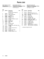
1
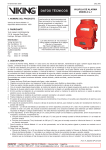
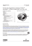
Instructions -- Parts List
1:1 RATIO
307906W
EN
Fast-Ballt Pumps
For non--abrasive and non--corrosive oils and lubricants only.
180 psi (1.2 MPa, 12.4 bar) Maximum Air and Fluid Working Pressure
Oil Pumps
CAUTION
These pumps are designed to pump lubricating
fluids only.
Model No. 222051, Series E
Universal Pump
Model No. 222103, Series E
55-Gallon Drum, Bung-Mount Pump
Model No. 222104, Series E
275-Gallon Tank, Bung-Mount Pump
Important Safety instructions
Read all warnings and instructions in this manual.
Save these instructions.
See page 2 for Table of Contents.
Model 222051
05939B
Models 222103
222104
GRACO INC. P.O. BOX 1441 MINNEAPOLIS, MN 55440- 1441
Copyright 1989, Graco Inc. is registered to I.S. EN ISO 9001
05940B
Table of Contents
Symbols
Warning Symbol
Warnings . . . . . . . . . . . . . . . . . . . . . . . . . . . . . . . . . . . . . . 2
Installation . . . . . . . . . . . . . . . . . . . . . . . . . . . . . . . . . . . . . 5
Operation . . . . . . . . . . . . . . . . . . . . . . . . . . . . . . . . . . . . . 8
Troubleshooting . . . . . . . . . . . . . . . . . . . . . . . . . . . . . . . . 9
Service . . . . . . . . . . . . . . . . . . . . . . . . . . . . . . . . . . . . . . 10
Parts List . . . . . . . . . . . . . . . . . . . . . . . . . . . . . . . . . . . . . 12
Parts Drawing . . . . . . . . . . . . . . . . . . . . . . . . . . . . . . . . . 13
Dimensional Drawing . . . . . . . . . . . . . . . . . . . . . . . . . . 14
Technical Data . . . . . . . . . . . . . . . . . . . . . . . . . . . . . . . . 14
Performance Curves . . . . . . . . . . . . . . . . . . . . . . . . . . . 15
Graco Standard Warranty . . . . . . . . . . . . . . . . . . . . . . 16
Graco Information . . . . . . . . . . . . . . . . . . . . . . . . . . . . . 16
WARNING
This symbol alerts you to the possibility of serious
injury or death if you do not follow the instructions.
Caution Symbol
CAUTION
This symbol alerts you to the possibility of damage to
or destruction of equipment if you do not follow the
instructions.
WARNING
EQUIPMENT MISUSE HAZARD
Equipment misuse can cause the equipment to rupture or malfunction and result in serious injury.
D This equipment is for professional use only.
D Read all instruction manuals, tags, and labels before you operate the equipment.
D Use the equipment only for its intended purpose. If you are not sure, call your Graco distributor.
D Do not alter or modify this equipment. Use only genuine Graco parts and accessories.
D Check equipment daily. Repair or replace worn or damaged parts immediately.
D Do not exceed the maximum working pressure of the lowest rated component in your system.
This equipment has a 180 psi (1.2 MPa, 12.4 bar) maximum working pressure at 180 psi
(1.2 MPa, 12.4 bar) maximum incoming air pressure.
D Use fluids and solvents that are compatible with the equipment wetted parts. Refer to the Technical Data section of all equipment manuals. Read the fluid and solvent manufacturer’s warnings.
D Do not use 1,1,1--trichloroethane, methylene chloride, other halogenated hydrocarbon solvents,
or fluids that contain such solvents in pressurized aluminum equipment. Such use could result in
a chemical reaction, with the possibility of explosion.
D Handle hoses carefully. Do not pull on hoses to move equipment.
D Route hoses away from traffic areas, sharp edges, moving parts, and hot surfaces. Do not expose Graco hoses to temperatures above 82_C (180_F) or below --40_C (--40_F).
D Do not lift pressurized equipment.
D Comply with all applicable local, state, and national fire, electrical, and safety regulations.
2
307906
WARNING
SKIN INJECTION HAZARD
Fluid from the dispensing valve, leaks, or ruptured components can inject fluid into your body and
cause extremely serious injury, including the need for amputation. Fluid splashed in the eyes or on
the skin can also cause serious injury.
D If a fluid injection injury occurs, get immediate surgical treatment. Do not treat as a simple
cut. Tell the doctor exactly what fluid was injected.
D Do not point the dispensing valve at anyone or at any part of the body.
D Do not put your hand or fingers over the end of the dispensing valve.
D Do not stop or deflect leaks with your hand, body, glove, or rag.
D Use only extensions and no-drip tips that are designed for use with your dispensing valve.
D Do not use a low pressure flexible nozzle with this equipment.
D Follow the Pressure Relief Procedure on page 8 if the dispensing valve clogs before you
clean, check, or service the equipment.
D Tighten all fluid connections before you operate the equipment.
D Check the hoses, tubes, and couplings daily. Replace worn or damaged parts immediately. Do
not repair high pressure couplings; you must replace the entire hose.
TOXIC FLUID HAZARD
Hazardous fluids or toxic fumes can cause serious injury or death if splashed in the eyes or on the
skin, inhaled, or swallowed.
D Know the specific hazards of the fluid you are using.
D Store hazardous fluid in an approved container. Dispose of hazardous fluid according to all local,
state and national guidelines.
D Always wear protective eyewear, gloves, clothing, and respirator as recommended by the fluid
and solvent manufacturer.
307906
3
WARNING
FIRE AND EXPLOSION HAZARD
Improper grounding, poor ventilation, open flames, or sparks can cause a hazardous condition and
result in a fire or explosion and serious injury.
D Ground the equipment and the object being lubricated. See Grounding on page 6.
D If there is any static sparking or you feel an electric shock while using this equipment, stop
dispensing immediately. Do not use the equipment until you identify and correct the problem.
D Provide fresh air ventilation to avoid the buildup of flammable fumes from solvents or the fluid
being dispensed.
D Keep the dispensing area free of debris, including solvent, rags, and gasoline.
D Do not smoke in the dispensing area.
MOVING PARTS HAZARD
Moving parts can pinch or amputate your fingers or other body parts.
D Do not cycle the pump with any parts disassembled.
D Keep clear of all moving parts when you start or operate the pump.
D Before you service the equipment, follow the Pressure Relief Procedure on page 8 to prevent
the equipment from starting unexpectedly.
United States Government safety standards have been adopted under the Occupational Safety and Health Act. You
should consult these standards----particularly the General Standards, Part 1910.
4
307906
Installation
A
A
Main Air Line
Main Fluid Line
B
C
D
E
B
F
C
D E F
P
P
Q
Q
G
J
R
N
G
28
H
N
R
H
M
K
L
KEY
A
B
C
D
E
F
G
H
Air shutoff valve
Air filter
Air regulator and gauge
Air motor lubricator
Bleed-type master air valve (required, Part No. 110223)
Air and fluid hose kits
Ground wire (required, Part No. 222011)
Fluid shutoff valve
Wall bracket
Universal pump (Model 222051)
Suction kit
55-gallon drum bung-mount pump (Model 222103)
Fluid drain valve (required, Part No. 210658)
Air inlet
Ball valve (for releasing collected moisture)
Thermal relief kit (required for permanent
installations, Part No. 237601)
28 Bung adapter
J
K
L
M
N
P
Q
R
05942B
Fig. 1
Install the accessories in the order shown in the typical installation in Fig. 1. The installation shown in Fig. 1 is only
a guide for selecting and installing a pump; it is not an actual system design. Contact your Graco representative for
assistance in designing a system to suit your needs.
NOTE: Blow out all lines with compressed air before you connect the pumps.
CAUTION
Always mount the pump firmly to a wall bracket or
a bung on a drum. Never operate the pump while it
is not mounted. Such use could damage the pump
and fittings.
CAUTION
Do not hang the air accessories directly on the air
inlet (P). The fittings are not strong enough to
support the accessories and may break. Provide a
bracket on which to mount the accessories.
307906
5
Installation
Grounding
System Accessories
Proper grounding is an essential part of maintaining a
safe system.
To reduce the risk of static sparking, ground the pump.
Check your local electrical code for detailed grounding
instructions for your area and type of equipment. Be
sure to ground all of this equipment:
D Pump: Use a ground wire and clamp as shown in
Fig. 2.
D Air compressor: Follow the manufacturer’s recommendations.
D Object being dispensed to: Follow the local code.
D Fluid supply container: Follow the local code.
D To maintain grounding continuity when flushing or
relieving pressure, always hold a metal part of the
dispensing valve firmly to the side of a grounded
metal container, then trigger the valve.
To ground the pump, remove the ground screw (Z)
and insert through the eye of the ring terminal at end of
ground wire (Y). Fasten the ground screw back onto
the pump and tighten securely. Connect the other end
of the wire to a true earth ground. To order a ground
wire and clamp, order Part No. 222011.
WARNING
Three accessories are required in your system:
bleed-type master air valve, fluid drain valve, and
grounding wire. Additionally, for permanent installations, a thermal relief kit is required. These accessories help reduce the risk of serious bodily injury,
including fluid injection, splashing in the eyes or on
the skin, injury from moving parts if you are adjusting or repairing the pump, and explosion from
static sparking.
D The bleed-type master air valve (E) relieves air
trapped between it and the air motor after the
air supply is shut off. Trapped air can cause the
air motor to cycle unexpectedly, causing serious
injury if you are adjusting or repairing the pump.
As an alternative, use a quick-disconnect
coupler and fitting. Install them near the pump
air inlet within easy reach from the pump.
D The fluid drain valve (N) assists in relieving fluid
pressure in the displacement pump, hoses, and
dispensing valve. Triggering the valve to relieve
pressure may not be sufficient.
D The ground wire (G) reduces the risk of static
sparking.
D The thermal relief kit (R) assists in relieving
pressure in the pump, hose, and dispensing
valve due to heat expansion.
D Extension Tubes: Pump models 222103 and
222104 have extensions tubes. An extension tube
may be added to the Universal pump for use in
submerged applications. To install, apply PTFE
tape to the female threads at the top of the tube.
Thread the tube tightly into the intake housing of
the Universal pump. Also, install a bung adapter. To
order a standard 2-in. bung adapter, order Part No.
222308.
Z
D Air and Fluid Hose Kits (F): An 18-in. kit for wallmounted pumps and a 6-ft. kit for drum-mounted
pumps are available. Use a minimum 1/4-in. ID air
supply hose between the pump air inlet and the air
accessories. To order a kit with 1/4-in. air hose,
1/4-in. swivel elbow, 3/4-in. fluid hose, and 3/4-in.
swivel elbow, order one of the kits below:
Y
222118 18-in. (0.4 m) hose kit for wall-mounted
pumps
05941B
Fig. 2
6
307906
222119 6-ft (1.8 m) hose kit for drum-mounted
pumps
Installation
D Wall Bracket: Use the wall bracket (J) for wall
mounting the Universal pump. This wall bracket is
sized to fit any Graco pump designed to use a 2-in.
bung adapter. Order Part No. 203987.
D Runaway Valve: Install a pump runaway valve to
shut off the air to the pump when the pump accelerates beyond the pre-adjusted setting. A pump that
is in a runaway condition can be seriously damaged.
CAUTION
Never allow the pump to run dry of the fluid being
pumped. A dry pump quickly accelerates to a high
speed, possibly damaging itself, and it may get
very hot.
D Bleed-Type Master Air Valve: Install a bleed-type
master air valve (E) to relieve air trapped between it
and the motor when the valve is closed. To order a
300 psi (2.1 MPa, 21 bar), 1/4-in. npt(f) bleed-type
master air valve, order Part No. 110223.
D Suction Kit: The suction kit (L) is for use with the
wall-mounted Universal pump, and it includes a
drum tube and hose. To order a suction kit, order
Part No. 213099.
D Air Motor Lubricator: The air motor lubricator (D)
provides automatic air motor lubrication. To order a
250 psi (1.7 MPa, 17.4 bar) 1/4-in. npt(f) air motor
lubricator, order Part No. 110148.
D Air Regulator and Gauge: Use the air regulator and
gauge (C) to control air pressure and pump speed.
To order a 0 to 200 psi (0 to 1.4 MPa, 0 to 14 bar)
regulated pressure range (300 psi [2.1 MPa,
21 bar] maximum), 1/4-in npt(f) air regulator and
gauge, order Part No. 110147.
D Air Filter: The air filter (B) removes harmful dirt and
moisture from the compressed air supply. To order
a 300 psi (2.1 MPa, 21 bar), 1/4-in npt(f) air filter
(20-micron element), order Part No. 110146.
D Air and Fluid Shutoff Valves: Install air shutoff
valves (A) and fluid shutoff valves (H) as shown to
isolate the pump while you are servicing it.
D Quick-Disconnect Coupler and Nipple: The quickdisconnect coupler and nipple (not shown) are used
to quickly disconnect the air supply. Attach the
coupler (Part No. 208536) to the pump air inlet
hose, and install the nipple (Part No. 169970) to the
pump air inlet (P).
D Thermal Relief Kit: Install the thermal relief kit on
the dispensing valve side of the pump to assist in
relieving pressure in the pump, hose, and dispensing valve due to heat expansion. To order a 600 psi
(4.2 MPa, 41 bar) Thermal Relief Kit, order Part No.
237601.
307906
7
Operation
Pressure Relief Procedure
WARNING
PRESSURIZED FLUID HAZARD
This equipment stays pressurized until
pressure is manually relieved. To reduce
the risk of serious injury from moving
parts, pressurized fluid, accidental spray from the
valve, or splashing fluid, follow this procedure
whenever you do any of the following:
D
D
D
D
Are instructed to relieve pressure
Stop dispensing
Check, clean, or service any system equipment
Install or clean dispensing devices
1. Shut off the air supply to the pump.
2. Close the bleed-type master air valve (required in
your system).
3. Hold a metal part of the dispensing valve firmly to
a grounded metal waste container, and trigger the
valve to relieve pressure.
If you suspect that the nozzle or hose is completely
clogged, or that pressure has not been fully relieved
after you have followed the steps above, do the following: Wrap a rag around the hose end coupling and
relieve pressure gradually by very slowly partially
loosening the fitting. Then loosen completely, then
clear the obstruction.
WARNING
HAZARDOUS VAPORS
The air motor exhaust coming out of the
muffler could contain harmful materials,
such as oil, antifreeze, or some of the
material being pumped.
8
307906
To Start the Pump
1. Turn the air regulator to the minimum setting.
2. Direct the outlet hose into a waste container.
3. Open the bleed-type master air valve.
4. Slowly adjust the air regulator until the pump is
running smoothly and all air has been pumped out
of the pump and hoses. If the pump contains
solvent, be sure to pump it all into the waste
container.
5. Use the air regulator to control the pump speed
and cycle rate. Always use the lowest pressure
needed to obtain the desired results. This results
in optimum system efficiency and reduces pump
wear.
NOTES:
D The pump only takes a few strokes to prime. However, in a large system, it may take several minutes
to completely prime the fluid lines.
D Never allow a pump to run dry of the fluid being
pumped. A dry pump quickly speeds up and can
damage itself. If it speeds up, shut off the air supply
to the motor immediately. Refill the supply container, and prime the pump to eliminate air in the
fluid line.
D To prevent air from being sucked into the pump and
fluid lines if the supply container runs dry, use a
low-level cutoff valve at the pump intake. To order a
1 1/2-in. npt(f) thread connection low-level cutoff
valve, Order Part No. 203688.
Troubleshooting
Problem
Cause
Pump does not run.
Solution
There is no fluid demand.
In a closed-end system the pump runs only when
there is demand for fluid.
Air supply is insufficient.
Check air supply. Increase air pressure or volume.
Fluid outlet line or intake valve is
clogged.
Relieve the pressure. Check and clear obstructions.
Air motor parts are worn or
damaged.
Check the piston o-rings (15a*, 15b*) and exhaust
plate (15c*) for swelling. Replace if necessary. See
page 10.
Check the piston assembly (15). Be sure its screws
are properly torqued (10 to 14 in-lb [1.3 to 1.6 N-m])
and that the assembly is hand-tightened onto the
piston rod.
Check the springs (8, 17) for wear or damage, and
replace as needed.
Pump speeds up or runs
erratically.
Pump slows
erratically.
down
Material viscosity is too high.
Reduce viscosity. Reduce pump speed when running
viscous materials.
Pump throat packings, piston or
piston packings, or intake valve is
worn.
Relieve the pressure. Check and repair. See pages
10 and 11.
or runs Air motor is icing.
Shut off pump and allow to warm up. Run pump at a
lower air pressure.
Pump runs, but output is low on
up or down stroke.
Pump piston and/or intake valve is
worn.
Relieve the pressure. Check and repair. See pages
10 and 11.
Pump runs, but output is low on
both strokes.
Air supply is insufficient.
Check air supply. Increase air pressure or volume.
Fluid outlet line, intake valve, or
dispense valve is clogged.
Relieve the pressure. Check and clear obstructions.
WARNING
To reduce the risk of serious injury whenever you
are instructed to relieve pressure, always follow the
Pressure Relief Procedure on page 8.
307906
9
Service
NOTE: Clean and inspect all parts for wear or damage
when disassembled. Replace parts as needed. Repair
Kit 247431 is available. For the best results, use all
the parts in the kit. Parts included in the kit are marked
with an asterisk in the text, figures, Parts Drawing,
and Parts List.
Intake Valve
See the Parts Drawing on page 13.
1. Relieve the pressure.
WARNING
To reduce the risk of serious injury whenever you
are instructed to relieve pressure, always follow the
Pressure Relief Procedure on page 8.
2. Unscrew the valve housing (21). Remove the
o-ring (22*), ball (23), and retainer (20).
3. Inspect the parts for wear or damage. If the ball is
nicked, replace it. Apply liquid sealant to the male
threads, and reassemble.
Air Motor
See Fig. 3.
NOTE: Old, cured thread sealant on the piston rod
threads makes it necessary that you use tools to
remove the air piston assembly from the piston
rod. Do not use these tools when you screw
the air piston assembly onto the piston rod.
7. Disassemble the air piston assembly (15). See the
Piston Detail in Fig. 3. Clean all parts, and inspect
them for wear or damage. If any valve plate
spacers are damaged, replace all three in order to
maintain the correct clearance between the valve
plates and seals.
8. Check the spring (8) for wear or damage, and
replace as needed.
9. Apply sealant, such as LoctiteR green, to the
threads of the screws. Assemble the parts as
shown in the Piston Detail in Fig. 3. Torque the
screws to 10 to 14 in-lb (1.3 to 1.6 N-m).
Displacement Pump
See Fig. 3, and see the Parts Drawing on page 13.
WARNING
Do not cycle the pump with any parts disassembled. See the Moving Parts Hazard on page 4.
1. Relieve the pressure.
WARNING
To reduce the risk of serious injury whenever you
are instructed to relieve pressure, always follow the
Pressure Relief Procedure on page 8.
2. Remove the air hose and fluid hoses.
3. Place the air motor base (5) in a vise.
WARNING
To reduce the risk of injury from trapped air pressure when servicing the air motor, always remove
air cap (2) from air cylinder (4) before removing air
cylinder from base (5).
4. Remove the air cap (2). Gently pry the coils of the
spring (17) to remove the spring. Check the spring
for wear or damage, and replace as needed.
5. Use a strap wrench to unscrew the air cylinder (4)
from the base (5).
6. Unscrew the air piston assembly (15) from the
piston rod (10). Use pliers on the air exhaust plate
(15c*) and a wrench on the piston rod. See the
Piston Detail in Fig. 3.
10
307906
1. Use a strap wrench on the fluid cylinder (24) to
unscrew it from the motor base (5). Pull down on
the piston rod (10) until you have access to the
fluid piston assembly (19).
2. Stand the fluid piston assembly (19) in a vise, and
remove the piston rod (10).
3. Unscrew the fluid piston (19) from the piston
rod (10), and be careful not to drop the ball (18).
Remove the piston rod the rest of the way from the
base.
4. Remove the shaft seal (16*), wiper ring (11*), and
the gasket (9*) from the top of the motor base (5).
5. Reach inside the opening of the air motor base (5)
to remove the o-ring (26*). Carefully remove the
wiper ring (11*) and the seal (12*) from the motor
base.
6. Carefully inspect the smooth inner surface of the
fluid cylinder (24) for scoring or irregular surfaces.
Such damage causes premature packing wear and
leaking, so replace the part if needed.
7. Lubricate and install the new shaft seal (16*),
wiper ring (11*), and gasket (9*), seal (12*), wiper
ring (11*), and o-ring (26*) into the base.
8. Lubricate the new seal (19b*), and install it on the
fluid piston (19c).
9. Install washer (19a) onto fluid piston (19c).
Service
10. Place the ball (18) on the fluid piston (19c).
15. Lubricate the outside of the air piston assembly (15). Install the spring (17) into the cap (2).
Lubricate the gasket (6*), and install it in the cap.
Install the cap on the cylinder (4).
11. Apply thread sealant to the threads of the fluid
piston (19), screw the fluid piston onto the piston
rod (10), and torque to 23 ft-lb (31.2 NSm).
12. Install the air motor rod assembly by inserting it up
through the base from the bottom.
13. Install the spring (8) and the washer (7) on top of
the piston rod (10).
14. Apply sealant to the threads of the piston rod (10).
Carefully hand tighten the air piston assembly (15)
onto the piston rod until it is secure. Do not
tighten with tools.
16. Assemble the cylinder (4) onto the base (5). Screw
the cylinder and base together hand tight.
17. Screw the intake valve housing (21) of the
assembled intake valve assembly onto the fluid
cylinder (24).
18. Heavily lubricate the top inside diameter of the
fluid cylinder (24) and the outside threads. Carefully guide the fluid piston assembly into the fluid
cylinder. Push the fluid cylinder up, and screw it
into the pump base. Use a pipe wrench on the
knurled part of the intake valve housing (21) to
tighten the fluid cylinder and the intake valve.
2
15c*
17
6*
15d
4
15a*
15e
15b*
15
15f
7
8
15g Apply sealant to threads of screw,
and torque to 10 to 14 in-lb
(1.3 to 1.6 N-m).
10
air inlet
5
13
Piston Detail
pliers
15c*
15a*
fluid outlet
24
21
Fig. 3
0.032 in.
(0.8 mm)
minimum
NOTE: Use pliers and
wrench only for loosening
the piston assembly from
the piston rod. Do not use
them for tightening the
piston assembly.
15b*
wrench
intake valve
05943B
307906
11
Parts List
Model 222051, Series E
Universal Pump
Includes items 1 through 27
Ref.
No.
Part No.
1
2
3
4
5
6*
7
8
9*
10
11*
12*
13
15
168825
185218
185528
183520
162989
157872
157633
158109
191389
185428
110247
116343
24J679
15a*
15b*
15c*
15d
15e
15f
15g
108357
108358
162729
189210
181485
181487
220884
12
307906
Description
Model 222103, Series E
55-Gallon Drum Bung-Mount Pump
Includes items 1 through 26
and 28 through 31,
Qty.
AIR MOTOR
(includes items 2 through 17)
CAP, air motor
LABEL, identification
CYLINDER, air
BASE, air motor
GASKET
WASHER, valve
SPRING, compression, piston
GASKET
PISTON ROD
RING, wiper
SEAL
SCREW, ground
KIT, air valve
(includes items 15a through 15g)
.O-RING
.O-RING
.PLATE, air exhaust valve
PISTON
SPACER, valve plate
PLATE, valve
SCREW / GASKET assy
1
1
1
1
1
1
1
1
1
1
2
1
1
1
1
3
1
1
1
1
1
Model 222104, Series E
275-Gallon Tank Bung-Mount Pump
Includes items 1 through 26,
28 through 30, and 32
Ref.
No.
Part No.
Description
16*
17
18
19a
19b*
19c
20
21
22*
23
24
26*
28
30
31
32
121010
157630
100279
116153
116152
196802
157182
183009
156633
101190
196803
156641
222308
110127
191130
191131
SEAL, shaft
SPRING, compression, cap
BALL, steel 0.88” (22.2 mm) dia
WASHER
CUP, piston
PISTON, fluid
RETAINER, ball
HOUSING, intake valve
O-RING, nitrile rubber
BALL, steel; 1” (25 mm) dia
CYLINDER, fluid
O-RING, buna-N
BUNG ADAPTER
SPACER, foot
TUBE, extension, 55-gal drum
TUBE, extension, 275-gal tank
* Included in Repair Kit 247431
Qty.
1
1
1
1
1
1
1
1
1
1
1
1
1
1
1
1
Parts Drawing
2
9*
17
4
*16
11*
6
12*
5
6*
7
*11
4
15c*
3
13
5
15d
15
15a*
7
15e
8
15b*
15f
1
28
15g
*26
10
31, 32
3
24
19a
18
19b*
19c
30
2
*22
20
1
Torque to 10 to 14 in-lb (1.3 to 1.6 N-m).
2
Torque to 23 ft--lb (31.2 NSm).
3
Torque to 95 to 105 ft-lb (129 to 142 N-m).
4
Lips face up.
5
Lips face down.
6
Smaller OD up.
7
Smaller OD down.
23
21
05944B
307906
13
Dimensional Drawing
1/4
npt(f)
15.7 in.
(400 mm)
grounding screw
3/4 npt(f)
7.4 in.
(187 mm)
1 1/2 npt(f)
36.6 in.
(929 mm)
Model 222103
46.6 in.
(1183 mm)
Model 222104
extension tube
stand-off
05940B
Technical Data
Maximum working pressure . . . . . . . . . . . . . . . . . 180 psi
(1.2 MPa, 12.4 bar)
Fluid pressure ratio . . . . . . . . . . . . . . . . . . . . . . . . . . . 1:1
Air pressure range . . . . . . . . . . . . . . . . . . . . 40 to 180 psi
(0.28 to 1.2 MPa, 2.8 to 12.4 bar)
Air consumption . . . . . . . . . . . . . Approximately 1.5 cfm
(0.042 m3/min)
at 1 gpm (3.8 lpm) at 100 psi
(0.7 MPa, 7 bar) air pressure
Sound data*
Sound pressure level . . . . . . . . . . . . . . . . 74.9 dB(A)
Sound power level . . . . . . . . . . . . . . . . . . . 83.5 dB(A)
Effective piston area . . . . . . . . 1.48 sq in. (9.55 sq cm)
14
307906
Piston rod diameter . . . . . . . . . . . . . 1.375 in. (34.9 mm)
Stroke length . . . . . . . . . . . . . . . . . . . . . . 4 in. (101 mm)
Wetted parts . . . . . carbon steel, aluminum, urethane,
UHMWPE
Approximate weight
Model 222051 . . . . . . . . . . . . . . . . . . . . 8 lb (3.6 kg)
Model 222103 . . . . . . . . . . . . . . . . . . . 13 lb (5.9 kg)
Model 222104 . . . . . . . . . . . . . . . . . . . 14 lb (6.4 kg)
Maximum temperature . . . . . . . . . . . . . . . 180_F (82_C)
*
Sound measurements were taken at 100 psi air
(0.7 MPa, 7 bar) inlet pressure at 40 cycles per
minute per ISO Standard 3744.
LoctiteR is a registered trademark of Loctite
Corporation.
Performance Curves
Fluid
Outlet Pressure,
psi
(MPa, bar)
Air
Consumption
scfm
(m#/min)
black curves=fluid outlet pressure
gray curves=air consumption
KEY
150
(1.0, 10.4)
D
125
(0.85, 8.5)
A
B
C
D
10
(0.280)
40 psi (0.28 MPa, 2.8 bar) air pressure
70 psi (0.48 MPa, 4.8 bar) air pressure
100 psi (0.7 MPa, 7 bar) air pressure
150 psi (1.0 MPa, 10.4 bar) air pressure
100
8
(0.224)
(0.7, 7)
C
75
6
(0.168)
(0.51, 5.1)
D
B
50
4
(0.34, 3.4)
(0.112)
C
B
25
(0.17, 1.7)
2
A
(0.056)
A
0
0
1
(3.8)
2
(7.6)
3
(11.4)
4
(15.1)
5
(18.9)
FLUID FLOW----gpm (lpm)
Test Fluid: No. 10 weight oil at 75_ F (23.9_ C)
To find fluid outlet pressure at a specific fluid flow
and operating air pressure:
To find pump air consumption at a specific fluid
flow and air pressure:
1. Locate desired fluid flow along bottom of chart.
1. Locate desired flow along bottom of chart.
2. Follow vertical line up to intersection with
selected fluid outlet pressure curve (black).
2. Read vertical line up to intersection with
selected air consumption curve (gray).
3. Follow left to scale to read fluid outlet pressure.
2. Follow right to scale to read air consumption.
307906
15
Graco Standard Warranty
Graco warrants all equipment manufactured by Graco and bearing its name to be free from defects in material and workmanship on the
date of sale to the original purchaser for use. With the exception of any special, extended, or limited warranty published by Graco,
Graco will, for a period of twelve months from the date of sale, repair or replace any part of the equipment determined by Graco to be
defective. This warranty applies only when the equipment is installed, operated and maintained in accordance with Graco’s written
recommendations.
This warranty does not cover, and Graco shall not be liable for general wear and tear, or any malfunction, damage or wear caused by
faulty installation, misapplication, abrasion, corrosion, inadequate or improper maintenance, negligence, accident, tampering, or substitution of non--Graco component parts. Nor shall Graco be liable for malfunction, damage or wear caused by the incompatibility of
Graco equipment with structures, accessories, equipment or materials not supplied by Graco, or the improper design, manufacture,
installation, operation or maintenance of structures, accessories, equipment or materials not supplied by Graco.
This warranty is conditioned upon the prepaid return of the equipment claimed to be defective to an authorized Graco distributor for
verification of the claimed defect. If the claimed defect is verified, Graco will repair or replace free of charge any defective parts. The
equipment will be returned to the original purchaser transportation prepaid. If inspection of the equipment does not disclose any defect
in material or workmanship, repairs will be made at a reasonable charge, which charges may include the costs of parts, labor, and
transportation.
THIS WARRANTY IS EXCLUSIVE, AND IS IN LIEU OF ANY OTHER WARRANTIES, EXPRESS OR IMPLIED, INCLUDING BUT
NOT LIMITED TO WARRANTY OF MERCHANTABILITY OR WARRANTY OF FITNESS FOR A PARTICULAR PURPOSE.
Graco’s sole obligation and buyer’s sole remedy for any breach of warranty shall be as set forth above. The buyer agrees that no other
remedy (including, but not limited to, incidental or consequential damages for lost profits, lost sales, injury to person or property, or any
other incidental or consequential loss) shall be available. Any action for breach of warranty must be brought within two (2) years of the
date of sale.
Graco makes no warranty, and disclaims all implied warranties of merchantability and fitness for a particular purpose in connection
with accessories, equipment, materials or components sold but not manufactured by Graco. These items sold, but not manufactured
by Graco (such as electric motors, switches, hose, etc.), are subject to the warranty, if any, of their manufacturer. Graco will provide
purchaser with reasonable assistance in making any claim for breach of these warranties.
In no event will Graco be liable for indirect, incidental, special or consequential damages resulting from Graco supplying equipment
hereunder, or the furnishing, performance, or use of any products or other goods sold hereto, whether due to a breach of contract,
breach of warranty, the negligence of Graco, or otherwise.
FOR GRACO CANADA CUSTOMERS
The parties acknowledge that they have required that the present document, as well as all documents, notices and legal proceedings
entered into, given or instituted pursuant hereto or relating directly or indirectly hereto, be drawn up in English. Les parties reconnaissent avoir convenu que la rédaction du présente document sera en Anglais, ainsi que tous documents, avis et procédures judiciaires
exécutés, donnés ou intentés à la suite de ou en rapport, directement ou indirectement, avec les procedures concernées.
Graco Information
TO PLACE AN ORDER, contact your Graco distributor, or call one of the following numbers
to identify the distributor closest to you:
1--800--533--9655 Toll Free
612--623--6928
612--378--3590 Fax
All written and visual data contained in this document reflects the latest product information available at the time of publication.
Graco reserves the right to make changes at any time without notice.
This manual contains English. MM 307906
For patent information: www.graco.com/patents
Graco Headquarters: Minneapolis
International Offices: Belgium, Korea, China, Japan
www.graco.com
02/1989, Revised February 2014
16
307906