1
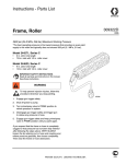
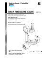
Instructions – Parts List
Parts
BACK PRESSURE VALVE
306770J
300 psi (2.1 MPa, 21 bar) Maximum Inlet Pressure
180 psi (1.2 MPa, 12 bar) Maximum Regulated Pressure
Model 206019, Series F
For use with Monark, President and 5:1 Bulldog pumps
in circulating supply systems.
D Controls line pressures from 0–180 psi (0–1.2 MPa, 0–12 bar).
D Tungsten carbide valve stem and seat.
D Maintains fluid pressure in circulating supply system.
7865
Read warnings and instructions.
See page 2 for Table of Contents.
GRACO INC.ąP.O. BOX 1441ąMINNEAPOLIS, MNą55440-1441
Copyright 2002, Graco Inc. is registered to I.S. EN ISO 9001
Table of Contents
Warnings . . . . . . . . . . . . . . . . . . . . . . . . . . . . . . . . . . . . . .
Installation . . . . . . . . . . . . . . . . . . . . . . . . . . . . . . . . . . . . .
Operation . . . . . . . . . . . . . . . . . . . . . . . . . . . . . . . . . . . . .
Service . . . . . . . . . . . . . . . . . . . . . . . . . . . . . . . . . . . . . . .
Parts . . . . . . . . . . . . . . . . . . . . . . . . . . . . . . . . . . . . . . . . .
Dimensions . . . . . . . . . . . . . . . . . . . . . . . . . . . . . . . . . . . .
Technical Data . . . . . . . . . . . . . . . . . . . . . . . . . . . . . . . . .
Graco Standard Warranty . . . . . . . . . . . . . . . . . . . . . . .
Graco Phone Numbers . . . . . . . . . . . . . . . . . . . . . . . . . .
Symbols
2
4
5
5
6
7
7
8
8
Warning Symbol
WARNING
This symbol alerts you to the possibility of serious
injury or death if you do not follow the instructions.
Caution Symbol
CAUTION
This symbol alerts you to the possibility of damage to
or destruction of equipment if you do not follow the
corresponding instructions.
2
306770
WARNING
PRESSURIZED EQUIPMENT HAZARD
Spray from the gun, hose leaks, or ruptured components can splash fluid in the eyes or on the skin
and cause serious injury.
D Do not stop or deflect fluid leaks with your hand, body, glove, or rag.
D Follow the Pressure Relief Procedure for your equipment if the spray tip clogs and before cleaning, checking, or servicing the equipment.
D Tighten all the fluid connections before operating the equipment.
D Check the hoses, tubes, and couplings daily. Replace worn, damaged, or loose parts immediately.
Permanently coupled hoses cannot be repaired; replace the entire hose.
EQUIPMENT MISUSE HAZARD
Equipment misuse can cause the equipment to rupture or malfunction and result in serious injury.
INSTRUCTIONS
D This equipment is for professional use only.
D Read all instruction manuals, tags, and labels before operating the equipment.
D Use the equipment only for its intended purpose. If you are uncertain about usage, call your Graco
distributor.
D Do not alter or modify this equipment. Use only genuine Graco parts and accessories.
D Check equipment daily. Repair or replace worn or damaged parts immediately.
D Do not exceed the maximum working pressure of the lowest rated system component. Refer to the
Technical Data on page 7 for the maximum working pressure of this equipment.
D Use fluids and solvents that are compatible with the equipment wetted parts. Refer to the Technical Data section of all equipment manuals. Read the fluid and solvent manufacturer’s warnings.
D Do not exceed the maximum working pressure of the lowest rated system component. This equipment has a 300 psi (2.1 MPa, 21 bar) maximum inlet pressure.
D Do not use hoses to pull equipment.
D Route hoses away from traffic areas, sharp edges, moving parts, and hot surfaces. Do not expose
Graco hoses to temperatures above 82_C (180_F) or below –40_C (–40_F).
D Wear hearing protection when operating this equipment.
D Do not lift pressurized equipment.
D Comply with all applicable local, state, and national fire, electrical, and safety regulations.
D Never use 1.1.1–trichloroethane, methylene chloride, other halogenated hydrocarbon solvents or
fluids containing such solvents in pressurized aluminum equipment. Such use could result in a
chemical reaction, with the possibility of explosion.
306770
3
Installation
Typical Installation
F
E
A
B
D
KEY
A
B
C
D
E
F
Fluid Pressure Regulator
Air Spray Gun
Fluid Return Line
Back Pressure Valve
Air Supply Line
Fluid Supply Line
C
7867
CAUTION
Before installing the valve, check the tightness of the
capscrews (4). The screws might be loose before the
valve is installed and put under pressure. See the
Parts Drawing for the tightening sequence and
torque value. After 24 hours, or if the valve leaks
during operation, check and torque the screws again.
4
306770
Install the valve in the spray gun return line (See the
Typical Installation). Connect the line to the 1 in.
npt(f) inlet and outlet. Make sure flow agrees with IN
and OUT markings on the valve body.
If more than one spray station is used, the back pressure valve should be installed in the supply line after
the last station to maintain proper circulating pressures
in the system.
Operation
The valve is adjustable to control fluid pressures in a
circulating system from 0–180 psi (0–1.2 MPa, 0–12
bar).
Adjust the pump pressure and back pressure valve for
best spraying combination and for proper circulation of
fluid.
The back pressure valve controls pressure ahead of its
intake.
Turn the adjusting screw (16) CLOCKWISE to increase pressure, and COUNTERCLOCKWISE to
decrease pressure.
Flush the valve with a compatible solvent whenever
the rest of the system or unit (pump, spray valve, etc.)
is being flushed. Open the valve before flushing (turn
the screw counterclockwise).
Service
WARNING
Always open the valve and relieve the system
pressure before servicing.
Regular cleaning and inspection of the valve, based
upon the degree and kind of service, is essential.
Shut off the pump and relieve the line pressure by
turning the valve adjusting screw counterclockwise
until no spring tension is felt.
To clean and inspect the valve, remove it from the line,
disassemble, and clean with a compatible solvent.
CAUTION
Use special care in handling the valve to avoid
damaging the diaphragm (11) and the hard carbide
valve stem (15) and seat (19).
Carefully inspect the diaphragm (11) for cracks or
other damage. Before reassembling, check for chips or
other dirt that could puncture the diaphragm. Check
also to see if the gasket (12) needs to be replaced.
Reinstall the diaphragm parts in reverse order. Torque
the retaining nut (9) to 12–15 ft-lb (16–20 NSm).
Carefully inspect the seat (19) for damage or wear.
Obstructing dirt could cause regulated pressure to
creep. Replace if necessary.
Replace the seat gasket (14) when replacing the seat
(19). Torque the seat to 15–20 ft-lb (21–27 NSm).
To remove or install the gauge (2), use a wrench on
the square portion of the gauge stud only. Use thread
sealer sparingly on the male threads of the gauge
when installing to prevent plugging the gauge.
Reassemble the remainder of the parts in reverse
order. Tighten valve capscrews (4) per sequence
shown on page 6. Check the torque after 24 hours,
and re-torque if necessary or if leaking occurs. Reinstall the back pressure valve in the line.
306770
5
Parts
Model 206019, Series F
1
Torque to 120–130 in-lb (13.6–14.7 NSm).
See Detail A for torque sequence.
2
Torque to 12–15 ft-lb (16–20 NSm).
3
PTFE side down.
DETAIL A
ÎÎ
Î
ÎÎ
Î
ÎÎ
Î
ÎÎ
Î
5
3
NOTE: Numbers indicate
capscrew (4) tightening sequence. Torque evenly to
7–10 in-lb (0.8–1.1 NSm),
then re-torque to 120–130
in-lb (13.6–14.7 NSm)
2
4
1
6
16
*2
1
11*
3
12†
4
20†
18
17
6
15†
†3
19†
14†
7
10
13
2
9
8
21
7866
Ref
No. Part No.
2*
101180
3†
104430
4
6
7
8
9
10
11†
12†
13
101682
160033
160034
164864
160741
160745
172193
171912
165750
6
306770
Description
Qty
GAUGE; 0–200 psi
(0–1.4 MPa, 0–14 bar)
1
PIN, cotter; 0.06” (1.5 mm) dia, 0.75”
(19 mm) lg
1
SCREW, soc hd cap; 1/4–20 x 5/8 6
PLATE, spring
1
SPRING, helical compression
1
PLATE, diaphragm
1
NUT, special lock; diaphragm
1
TUBE, gauge
1
DIAPHRAGM
1
GASKET; cellulose fibre
1
BODY, valve (electroless nickle
plated)
1
Ref
No. Part No.
Description
14†
15†
16
17
18
19†
20†
21
GASKET, acetal
STEM, valve
SCREW, adjusting
SUPPORT, diaphragm
CAP, valve
SEAT, valve
GASKET; cellulose fibre
PACKING, o-ring; thiokol
166964
203375
186872
203985
209027
206275
171913
157277
* Recommended tool box spare parts. Keep on hand to
reduce down time.
† Included in Repair Kit 210754.
Qty
1
1
1
1
1
1
1
1
Dimensions
3.875” (98 mm)
Diameter
1 npt(f)
Fluid Outlet
8”
(203 mm)
5.75”
(146 mm)
1 npt(f)
Fluid Inlet
7865
Technical Data
Maximum Inlet Pressure . . . . . . . . . . . . . . . . . . . . . . . . . . . 300 psi (2.1 MPa, 21 bar)
Pressure Control Range . . . . . . . . . . . . . . . . . . . . . 0–180 psi (0–1.2 MPa, 0–12 bar)
Approx. Maximum Flow . . . . . . . . . . . . . . . . . . . . . . . . . . . . . . . 6 gpm (22.7 liters/min)
with 100 centipose fluid at 60 psi (400 kPa, 4 bar)
Fluid Inlet Port . . . . . . . . . . . . . . . . . . . . . . . . . . . . . . . . . . . . . . . . . . . . . . . . . . . . . 1 npt(f)
Fluid Outlet Port . . . . . . . . . . . . . . . . . . . . . . . . . . . . . . . . . . . . . . . . . . . . . . . . . . . 1 npt(f)
Weight . . . . . . . . . . . . . . . . . . . . . . . . . . . . . . . . . . . . . . . . . . . . . . . . . . . . . . . 4 lb (1.8 kg)
Wetted Parts . . . . . . . . . . . . . . . . . . . . . . . . . . . . . . . Tungsten Carbide, PTFE, Nylon,
Carbon Steel, Aluminum, Thiokolr
Thiokolr is a registered trademark of the Thiokol Chemical Corporation.
306770
7
Graco Standard Warranty
Graco warrants all equipment manufactured by Graco and bearing its name to be free from defects in material and workmanship on the
date of sale to the original purchaser for use. With the exception of any special, extended, or limited warranty published by Graco,
Graco will, for a period of twelve months from the date of sale, repair or replace any part of the equipment determined by Graco to be
defective. This warranty applies only when the equipment is installed, operated and maintained in accordance with Graco’s written
recommendations.
This warranty does not cover, and Graco shall not be liable for general wear and tear, or any malfunction, damage or wear caused by
faulty installation, misapplication, abrasion, corrosion, inadequate or improper maintenance, negligence, accident, tampering, or substitution of non–Graco component parts. Nor shall Graco be liable for malfunction, damage or wear caused by the incompatibility of
Graco equipment with structures, accessories, equipment or materials not supplied by Graco, or the improper design, manufacture,
installation, operation or maintenance of structures, accessories, equipment or materials not supplied by Graco.
This warranty is conditioned upon the prepaid return of the equipment claimed to be defective to an authorized Graco distributor for
verification of the claimed defect. If the claimed defect is verified, Graco will repair or replace free of charge any defective parts. The
equipment will be returned to the original purchaser transportation prepaid. If inspection of the equipment does not disclose any defect
in material or workmanship, repairs will be made at a reasonable charge, which charges may include the costs of parts, labor, and
transportation.
THIS WARRANTY IS EXCLUSIVE, AND IS IN LIEU OF ANY OTHER WARRANTIES, EXPRESS OR IMPLIED, INCLUDING BUT
NOT LIMITED TO WARRANTY OF MERCHANTABILITY OR WARRANTY OF FITNESS FOR A PARTICULAR PURPOSE.
Graco’s sole obligation and buyer’s sole remedy for any breach of warranty shall be as set forth above. The buyer agrees that no other
remedy (including, but not limited to, incidental or consequential damages for lost profits, lost sales, injury to person or property, or any
other incidental or consequential loss) shall be available. Any action for breach of warranty must be brought within two (2) years of the
date of sale.
Graco makes no warranty, and disclaims all implied warranties of merchantability and fitness for a particular purpose in connection
with accessories, equipment, materials or components sold but not manufactured by Graco. These items sold, but not manufactured
by Graco (such as electric motors, switches, hose, etc.), are subject to the warranty, if any, of their manufacturer. Graco will provide
purchaser with reasonable assistance in making any claim for breach of these warranties.
In no event will Graco be liable for indirect, incidental, special or consequential damages resulting from Graco supplying equipment
hereunder, or the furnishing, performance, or use of any products or other goods sold hereto, whether due to a breach of contract,
breach of warranty, the negligence of Graco, or otherwise.
FOR GRACO CANADA CUSTOMERS
The parties acknowledge that they have required that the present document, as well as all documents, notices and legal proceedings
entered into, given or instituted pursuant hereto or relating directly or indirectly hereto, be drawn up in English. Les parties reconnaissent avoir convenu que la rédaction du présente document sera en Anglais, ainsi que tous documents, avis et procédures judiciaires
exécutés, donnés ou intentés à la suite de ou en rapport, directement ou indirectement, avec les procedures concernées.
Graco Phone Numbers
TO PLACE AN ORDER, contact your Graco distributor, or call one of the following numbers
to identify the distributor closest to you:
1–800–367–4023 Toll Free
612–623–6921
612–378–3505 Fax
All written and visual data contained in this document reflects the latest product information available at the time of publication.
Graco reserves the right to make changes at any time without notice.
Sales Offices: Minneapolis, Detroit
International Offices: Belgium, Korea, Hong Kong, Japan
GRACO INC.
P.O. BOX 1441
MINNEAPOLIS, MN
www.graco.com
PRINTED IN U.S.A. 306770 01/1963, Revised 02/2004
8
306770
55440–1441