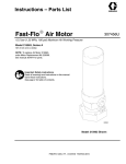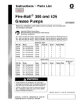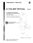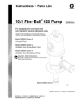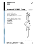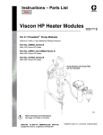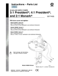
1
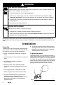
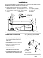
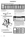
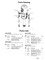
Instructions – Parts List
FIRE–BALL 300r and FIRE–BALL 425r
DRUM or TANK SUPPLY PUMPS
306520J
Used to pump petroleum and synthetic based oils.
5:1 Fire-Ball 300 Pump
Model 225852
900 psi (60 bar) Maximum Working Pressure
10:1 Fire–Ball 425 Pump
Model 225853
1800 psi (120 bar) Maximum Working Pressure
Important Safety Instructions.
Read all warnings and instructions in this manual.
Save these instructions.
Table of Contents
Warnings . . . . . . . . . . . . . . . . . . . . . . . . . . . . . . . . . . . . . . 2
Installation . . . . . . . . . . . . . . . . . . . . . . . . . . . . . . . . . . . . . 4
Operation . . . . . . . . . . . . . . . . . . . . . . . . . . . . . . . . . . . . . 8
Parts Drawing . . . . . . . . . . . . . . . . . . . . . . . . . . . . . . . . . . 9
Parts Lists . . . . . . . . . . . . . . . . . . . . . . . . . . . . . . . . . . . . . 9
Warranty . . . . . . . . . . . . . . . . . . . . . . . . . . . . . . . . . . . . . 10
Graco Phone Number . . . . . . . . . . . . . . . . . . . . . . . . . . 10
01494
Model 225852 Fire–Ball 300 shown
GRACO INC.ąP.O. BOX 1441ąMINNEAPOLIS, MNą55440-1441
Copyright 1955, Graco Inc. is registered to I.S. EN ISO 9001
Symbols
Warning Symbol
Caution Symbol
WARNING
CAUTION
This symbol alerts you to the possibility of serious
injury or death if you do not follow the instructions.
This symbol alerts you to the possibility of damage to
or destruction of equipment if you do not follow the
instructions.
WARNING
EQUIPMENT MISUSE HAZARD
Equipment misuse can cause the equipment to rupture or malfunction and result in serious injury.
D This equipment is for professional use only.
D Read all instruction manuals, tags, and labels before operating the equipment.
D Use the equipment only for its intended purpose. If you are not sure, call your Graco distributor.
D Do not alter or modify this equipment.
D Check equipment daily. Repair or replace worn or damaged parts immediately.
D Do not exceed the maximum working pressure stated on the equipment or in the Technical Data
for your equipment. Do not exceed the maximum working pressure of the lowest rated component in your system.
D Use fluids and solvents that are compatible with the equipment wetted parts. Refer to the Technical Data section of all equipment manuals. Read the fluid and solvent manufacturer’s warnings.
D Handle hoses carefully. Do not pull on hoses to move equipment.
D All fluid hoses must have spring guards on both ends. The spring guards help protect the
hose from kinks or bends at or close to the coupling, which can result in hose rupture.
D Route hoses away from traffic areas, sharp edges, moving parts, and hot surfaces. Do not
expose Graco hoses to temperatures above 82_C (180_F) or below –40_C (–40_F).
D Do not lift pressurized equipment.
D Comply with all applicable local, state, and national fire, electrical, and safety regulations.
D Use only dispensing valves that are designed to dispense motor oil. Do not modify any part of
the dispensing valve; doing so could cause a malfunction and result in serious bodily injury. Be
sure the dispensing valve has a maximum working pressure that meets or exceeds that of the
pump.
D The maximum fluid working pressure of these pumps, when operated at a maximum of 180 psi
(12.6 bar) air pressure is 900 psi (60 bar) on the 5:1 Fire-Ball 300 Pump, and it is 1800 psi
(120 bar) on the 10:1 Fire–Ball 425 Pump.
2
306520
WARNING
SKIN INJECTION HAZARD
Fluid from the dispensing valve, leaks, or ruptured components can inject fluid into your body and
cause extremely serious injury, including the need for amputation. Fluid splashed in the eyes or on
the skin can also cause serious injury.
D Fluid injected into the skin may look like just a cut, but it is a serious injury. Get immediate
surgical treatment.
D Do not point the dispensing valve at anyone or at any part of the body.
D Do not put your hand or fingers over the end of the dispensing valve.
D Do not stop or deflect leaks with your hand, body, glove, or rag.
D Use only extensions and tips that are designed for use with your dispensing valve.
D Tighten all fluid connections before operating the equipment.
D Check the hoses, tubes, and couplings daily. Replace worn or damaged parts immediately. Do
not repair high pressure couplings; you must replace the entire hose.
HAZARDOUS FLUIDS
Improper handling of hazardous fluids or inhaling toxic fumes can cause extremely serious injury or
death due to splashing in the eyes, ingestion, or bodily contamination.
D Know the specific hazards of the fluid you are using.
D Store hazardous fluid in an approved container. Dispose of hazardous fluid according to all local,
state, and national guidelines.
D Always wear protective eyewear, gloves, clothing, and respirator as recommended by the fluid
and solvent manufacturer.
306520
3
WARNING
FIRE AND EXPLOSION HAZARD
Improper grounding, poor ventilation, open flames, or sparks can cause a hazardous condition and
result in a fire or explosion and serious injury.
D Ground the equipment. Refer to Grounding below.
D If there is any static sparking or you feel an electric shock while using this equipment, stop
dispensing immediately. Do not use the equipment until you identify and correct the problem.
D Provide fresh air ventilation to avoid the buildup of flammable fumes from solvents or the fluid
being dispensed.
D Do not smoke in the dispensing area.
MOVING PARTS HAZARD
Moving parts can pinch or amputate your fingers.
D Keep clear of all moving parts when starting or operating the pump.
D Before servicing the equipment, follow the Pressure Relief Procedure on page 8 to prevent the
equipment from starting unexpectedly.
United States Government safety standards have been adopted under the Occupational Safety and Health Act.
You should consult these standards–particularly General Standards, Part 1910, and Construction Standards, Part
1926.
Installation
Grounding
To reduce the risk of static sparking, ground the pump.
Check your local electrical code for detailed grounding
instructions for your area and type of equipment.
D Pump: Use ground wire and clamp as shown in
Fig. 1.
D Air and fluid hoses: Use only electrically conductive
hoses.
D Air compressor: Follow manufacturer’s
recommendations.
D To maintain grounding continuity when flushing or
relieving pressure, always hold a metal part of the
dispensing valve firmly to the side of a metal pail,
and then open the dispensing valve.
To ground the pump:
To ground the pump, use a ground wire and clamp as
shown below. Remove the ground screw (Z) and insert
through the eye of ring terminal at end of ground wire
(Y). Fasten the ground screw back onto the pump and
tighten securely. Connect the other end of the ground
wire to a true earth ground. See Fig. 1. To order a
ground wire and clamp, order Part No. 222011.
D Dispensing valve: Obtain grounding through
connection to a properly grounded fluid hose and
pump.
D Fluid supply container: Follow your local code.
Z
Y
D Object being lubricated: Follow your local code.
D Any pails used when flushing: Use only metal,
grounded pails when flushing. Make firm
metal-to-metal contact between a metal part of the
dispensing valve and the pail. Use the lowest
possible pressure.
4
306520
Fig. 1
TI1052
Installation
The typical installation shown in Fig. 2 is only an installation guide; it is not an actual system design. Contact your
Graco distributor for assistance in designing a system to suit your needs.
A Maximum vertical lift, tank foot valve
to pump intake valve: 10 ft. (3 m)
B Suction line at pump: 9 in. (230 mm)
from wall
C Suction line at pump: 6 in. (150 mm)
above floor
D Vent pipe
E Pipe: 1.5 or 2 in. standard iron
F Horizontal suction line: 75 ft. (23 m)
maximum
G Stub assembly
H O.P.W. – Buckeye or equivalent
extractable suction
J Manhole cover
K
L
M
N
P
Q
R
Fill cap
4 in. (102 mm) standard pipe
Extractor fitting
4 in. (102 mm) from bottom of tank
1.5 in. foot valve
Swing joints
Gate valve
R B
D
C
ÎÎÎÎÎ
ÎÎÎÎÎ
E
C
ÎÎÎÎ
J
K
H
L
F
G
B
M
A
E
ÎÎÎÎ
ÎÎÎÎ
Q
Permanent Supply and Suction Lines
D Install pumps as close to the tanks as practical.
D Use 1.5 or 2 in. (38 mm or 50 mm) standard iron
pipe and heavy malleable iron fittings. Ream the
ends of iron pipe and use thread sealant for an
airtight system.
N
P
Fig. 2
01495
D Flush and test the lines under pressure before
covering or cementing in place.
D For installation dimensions for suction lines at the
pump end, see Fig. 3.
B
S
D Use long sweeping bends for turns in piping; avoid
unnecessary turns.
D All tube ends must be clean and free of burrs.
Ream the ends of iron pipe.
B
C
D Minimize the use of fittings.
D Avoid using unions and other connections
underground and in hard to reach places.
D For underground tanks, blow out and clean all lines
before installing them. Start the connections at the
storage tank end.
B 9 in. (230 mm),
Suction line at pump
C 6 in. (150 mm),
Suction line at pump
S 20 in. (510 mm),
Between suction lines
C
01496
Fig. 3
306520
5
Installation
Supply Lines From Pumps To Dispensing Units
Distance
Annealed Steel Tube
Annealed Copper Tube
Standard Iron Pipe
Min. O.D.
Min. Tube Wall
Fittings
Min. O.D.
Min. Tube Wall
< 25 ft. (7.6 m)
5/8 in.
0.035 in.
(0.89)
Flareless
5/8 in.
type K
0.049 in.
(1.24 mm)
Flared
1/2 in.
Heavy
malleable iron
> 25 ft. (7.6 m)
7/8 in.
0.035 in.
(0.89)
Flareless
7/8 in.
type K
0.065 in.
(1.65 mm)
Flared
3/4 in.
Heavy
malleable iron
> 75 ft. (23 m)
A
B
C
D
Fittings Min. Size
Fittings
Contact your Graco distributor
Incoming supply line
3/4 in. npt line strainer
Hose or pipe to metered unit
Position outlet down
1. Use a Y-type line strainer in oil supply lines. Locate
as close to the meter inlets as practical and where
they are easily accessible. Mount the strainer body
horizontally with the clean-out plug pointed down.
See Fig. 4. Periodically, relieve the pressure, and
remove and clean the metal strainers.
B
C
To order a 3/4 in. npt(f) line strainer, order Part No.
101078.
A
To order a 1/2 in. npt(f) line strainer, order Part No.
110877.
D
Fig. 4
WARNING
TO OUTLET
INJECTION HAZARD
To reduce the risk of serious injury
whenever you are instructed to relieve
pressure, always follow the Pressure
Relief Procedure on page 8.
D
A
2. See Fig. 5 for installation dimensions for the
supply line. Space the line ends to be adjacent to
the pump location. For annealed steel or copper
tubing lines, use a straight male coupling elbow
and a shutoff valve. For iron pipe, a shutoff valve
may be used instead. The shutoff valve must close
off 1/2 in. npt(f) openings for the Fire-Ball 300
pump, and it must close off 3/4 in. npt(f) openings
for the Fire–Ball 425 pump.
B
C
Air Lines
Air lines
A
B
C
D
3 in. (76 mm), Supply line to wall
20 in. (510 mm), Main fluid shutoff valves
24 in. (610 mm), Main air line to floor
20 in. (510 mm), Between suction lines
Fig. 5
6
01497
306520
Annealed Copper
Tube
Galvanized Pipe
O.D.
Type
L
Minimum
Wall
Thickness
Nominal
Size
Pump to
main air
1/2 or
3/8 in.
0.035 in.
(0.89 mm)
1/2 in. or 3/8 in.
Compressor
to main air
1/2 in.
0.035 in.
(0.89 mm)
1/2 in. or 3/8 in.
Installation
Air and Fluid Line Accessories
CAUTION
Do not hang the air accessories directly on the air
inlet. Mount them on brackets. The fittings are not
strong enough to support the accessories and may
break.
D Use thread sealant on male threads except at
swivel connections.
D Install a bleed-type master air valve upstream from
the pump air regulator, but within easy reach of the
pump.
To order a 300 psi (21 bar) maximum working
pressure, 1/2 in. npt bleed-type master air valve,
order Part No. 107142.
WARNING
A bleed-type master air valve is required in the
system to help reduce the risk of serious bodily
injury, including fluid injection, splashing in the
eyes, and injury from moving parts when
adjusting or repairing the pump. This valve
relieves air trapped between the valve and the
pump to prevent the pump from cycling unexpectedly.
D Install the pump end of the air supply lines about
24 in. (610 mm) above the floor.
D If you are installing several pumps, put tees in the
supply line immediately above and behind the pump
locations. See Fig. 5.
D Install an air line lubricator for automatic air motor
lubrication.
To order a 250 psi (17.5 bar) maximum working
pressure air line lubricator, order a Part No. below:
3/8 in. npt
1/2 in. npt
214847
214848
D Install an air regulator to control pump speed and
pressure.
To order a 300 psi (21 bar) maximum working
pressure regulator, order a Part No. below:
3/8 in. npt
1/2 in. npt
109075
104266
D Install an air line filter to remove harmful dirt and
contaminants from your compressed air supply.
To order a 250 psi (17.5 bar) maximum working
pressure air filter, order a Part No. below:
3/8 in. npt
1/2 in. npt
106148
214849
D Install a thermal relief kit on the dispensing valve
side of the pump to assist in relieving pressure in
the pump, hose, and dispensing valve due to heat
expansion.
To order a thermal relief kit for the Fire-Ball 300
pump—900 psi (62 bar) maximum working
pressure—order Part No. 237893.
To order a thermal relief kit for the Fire–Ball 425
pump—1600 psi (110 bar) maximum working
pressure—order Part No. 248324.
306520
7
Operation
Pressure Relief Procedure
WARNING
INJECTION HAZARD
To reduce the risk of serious bodily
injury, including fluid injection, injury from
moving parts, or splashing in the eyes or
on the skin, always follow this procedure whenever
you shut off the pump, when checking or servicing
any part of the system, when installing or changing
dispensing devices, and whenever you stop dispensing.
3. Disconnect the solvent supply, and connect the
supply lines to the tank.
4. Connect the fluid supply hose from the pump to
the dispensing valve.
Operating
WARNING
Never exceed 180 psi (12.6 bar) Maximum Air
Pressure to these pumps. Using higher air
pressure will cause the pump to overpressurize,
which may result in component rupture, fire, or
explosion and cause serious bodily injury.
1. Close the air regulator and disconnect the air
supply hose.
1. Open the bleed-type master air valve.
2. Close the pump’s bleed-type master air valve
(required in the system).
2. Slowly open the pump air regulator until the pump
is running smoothly.
3. Open the dispensing valve until pressure is fully
relieved.
3. Open the dispensing valve, and allow the system
to prime. When the system is fully primed, the
pump starts and stops as the dispensing valve is
opened and closed.
If you suspect that the dispensing valve is clogged, or
that pressure has not been fully relieved after following
the steps above, very slowly loosen the dispensing
valve coupler or hose end coupling to relieve pressure
gradually, then loosen completely.
Flushing
To reduce the risk of fluid injection injury, static
sparking, or splashing, relieve pressure, hold a metal
part of the dispensing valve firmly to the side of a
grounded metal pail and use the lowest possible fluid
pressure during flushing.
1. Before connecting the supply lines to the supply
tank, flush the pump and supply line with a
compatible solvent.
2. Connect the supply line to a solvent supply. Turn
on the main air, open the bleed-type master air
valve, and slowly open the pump air regulator until
the pump is cycling slowly. Use the lowest possible
pressure, and flush until the lines are thoroughly
cleaned. Shut off the pump, and relieve the
pressure.
WARNING
INJECTION HAZARD
To reduce the risk of serious injury
whenever you are instructed to relieve
pressure, always follow the Pressure
Relief Procedure above.
8
306520
CAUTION
Never allow the pump to run dry of the fluid
being pumped. A dry pump will quickly
accelerate to a high speed and possibly damage
itself. If the pump accelerates quickly, stop it
immediately, and check the fluid supply. If the
supply container is empty and air has been
pumped into the lines, prime the pump and lines
with fluid, or flush it and leave it filled with a
compatible solvent. Be sure to eliminate all air
from the fluid system.
4. Use the air regulator to control pump speed and
fluid pressure. Always use the lowest possible
pressure, which reduces pump wear.
5. When shutting off the system, and before checking
or servicing it, relieve the pressure.
WARNING
INJECTION HAZARD
To reduce the risk of serious injury
whenever you are instructed to relieve
pressure, always follow the Pressure
Relief Procedure at left.
Parts Drawing
4 or 6
13 or 18
12 or 17
11 or 16
10 or 15
01498
Parts Lists
Model 225852
Model 222062
5:1 Fire-Ball 300 Pump, Includes items 6, 7, 10 to 13
Hose Kit for Fire-Ball 300 pump
Ref
No. Part No.
Ref
No. Part No.
6
203876
7
222062
Description
Qty.
5:1 FIRE-BALL 300 PUMP, stubby
See manual 306518 for parts.
1
HOSE & FITTING KIT
See parts list to the right.
1
10
204560
11
220598
12
155494
10:1 Fire–Ball 425 Pump, Includes items 4, 5, 15 to 18
13
155470
Ref
No. Part No.
Model 222068
Model 225853
4
205626
5
222068
Description
Qty.
10:1 FIRE-BALL 425 PUMP, stubby
See manual 308655 for parts.
1
HOSE & FITTING KIT
See parts list to the right.
1
Description
Qty.
AIR HOSE, 3/8” ID, cpld
3/8–14 npt (mbe), 18” (457 mm)
FLUID HOSE, 1/2” ID, cpld
1/2–14 npt(mbe), 18” (457 mm)
UNION, 90_, 3/8–14 npt(m) x
3/8 npsm(f) swivel
UNION, 90_, 1/2–14 npt(m) x
1/2 npsm(f) swivel
1
1
1
1
Hose Kit for Fire–Ball 425 pump
Ref
No. Part No.
15
218093
16
109108
17
155470
18
160327
Description
Qty.
AIR HOSE, 1/2” ID, cpld
1/2–14 npt (mbe), 18” (457 mm)
FLUID HOSE, 3/4” ID, cpld
3/4–14 npt(mbe), 18” (457 mm)
UNION, 90_, 1/2–14 npt(m) x
1/2 npsm(f) swivel
UNION, 90_, 3/4–14 npt(m) x
3/4 npsm(f) swivel
306520
1
1
1
1
9
The Graco Warranty and Disclaimers
WARRANTY
Graco warrants all equipment manufactured by it and bearing its name to be free from defects in material and workmanship on the date
of sale to the original purchaser for use. As purchaser’s sole remedy for breach of this warranty, Graco will, for a period of twelve
months from the date of sale, repair or replace any part of the equipment proven defective. This warranty applies only when the
equipment is installed, operated and maintained in accordance with Graco’s written recommendations.
This warranty does not cover, and Graco shall not be liable for, any malfunction, damage or wear caused by faulty installation,
misapplication, abrasion, corrosion, inadequate or improper maintenance, negligence, accident, tampering, or substitution of
non-Graco component parts. Nor shall Graco be liable for malfunction, damage or wear caused by the incompatibility with Graco
equipment of structures, accessories, equipment or materials not supplied by Graco, or the improper design, manufacture,
installation, operation or maintenance of structures, accessories, equipment or materials not supplied by Graco.
This warranty is conditioned upon the prepaid return of the equipment claimed to be defective to an authorized Graco distributor for
verification of the claim. If the claimed defect is verified, Graco will repair or replace free of charge any defective parts. The equipment
will be returned to the original purchaser transportation prepaid. If inspection of the equipment does not disclose any defect in material
or workmanship, repairs will be made at a reasonable charge, which charges may include the costs of parts, labor and transportation.
DISCLAIMERS AND LIMITATIONS
The terms of this warranty constitute purchaser’s sole and exclusive remedy and are in lieu of any other warranties (express or
implied), including warranty of merchantability or warranty of fitness for a particular purpose, and of any non-contractual liabilities,
including product liabilities, based on negligence or strict liability. Every form of liability for direct, special, or consequential damages or
loss is expressly excluded and denied. In no case shall Graco’s liability exceed the amount of the purchase price. Any action for breach
of warranty must be brought within two (2) years of the date of sale.
EQUIPMENT NOT COVERED BY GRACO WARRANTY
Graco makes no warranty, and disclaims all implied warranties of merchantability and fitness for a particular purpose, with respect to
accessories, equipment, materials, or components sold but not manufactured by Graco. These items sold, but not manufactured by
Graco (such as electric motor, switches, hose, etc.) are subject to the warranty, if any, of their manufacturer. Graco will provide
purchaser with reasonable assistance in making any claim for breach of these warranties.
Graco Information
TO PLACE AN ORDER, contact your Graco distributor, or call one of the following numbers
to identify the distributor closest to you:
1–800–533–9655 Toll Free
612–623–6928
612–378–3590 Fax
All written and visual data contained in this document reflects the latest product information available at the time of publication.
Graco reserves the right to make changes at any time without notice.
This manual contains English. MM 306520
Graco Headquarters: Minneapolis
International Offices: Belgium, Korea, China, Japan
www.graco.com
306520 08/1955, Revised 01/2007
10
306520