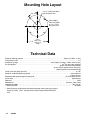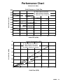
1
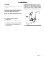
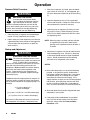
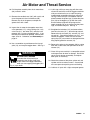
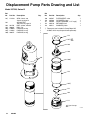
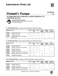
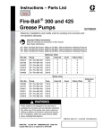
Instructions – Parts List
3:1 Fire–Ballr 425 Pump
308485N
For pumping non–corrosive and non–abrasive oils and lubricants.
Model 237526, Series B
540 psi (3.7 MPa, 37 bar) Maximum Working Pressure
180 psi (1.2 MPa, 12 bar) Maximum Air Input Pressure
Important Safety instructions
Read all warnings and instructions in this manual.
Save these instructions.
Table of Contents
Warnings . . . . . . . . . . . . . . . . . . . . . . . . . . . . . . . . . . . . . . 2
Installation . . . . . . . . . . . . . . . . . . . . . . . . . . . . . . . . . . . . . 5
Operation . . . . . . . . . . . . . . . . . . . . . . . . . . . . . . . . . . . . . 8
Troubleshooting Guide . . . . . . . . . . . . . . . . . . . . . . . . . . 9
Air Motor and Throat Service . . . . . . . . . . . . . . . . . . . . 10
Displacement Pump Service . . . . . . . . . . . . . . . . . . . . 13
Air Motor Parts Drawing . . . . . . . . . . . . . . . . . . . . . . . . 14
Air Motor Parts List . . . . . . . . . . . . . . . . . . . . . . . . . . . . 15
Displacement Pump Parts Drawing and List . . . . . . . 16
Dimensions . . . . . . . . . . . . . . . . . . . . . . . . . . . . . . . . . . . 17
Technical Data . . . . . . . . . . . . . . . . . . . . . . . . . . . . . . . . 18
Performance Data . . . . . . . . . . . . . . . . . . . . . . . . . . . . . 19
Warranty . . . . . . . . . . . . . . . . . . . . . . . . . . . . . . . . . . . . . 20
TI1066
GRACO INC.ąP.O. BOX 1441ąMINNEAPOLIS, MNą55440-1441
Copyright 1995, Graco Inc. is registered to I.S. EN ISO 9001
Symbols
Warning Symbol
Caution Symbol
WARNING
CAUTION
This symbol alerts you to the possibility of serious
injury or death if you do not follow the instructions.
This symbol alerts you to the possibility of damage to
or destruction of equipment if you do not follow the
instructions.
WARNING
EQUIPMENT MISUSE HAZARD
Equipment misuse can cause the equipment to rupture or malfunction and result in serious injury.
This equipment is for professional use only.
Read all instruction manuals, tags, and labels before operating the equipment.
Use the equipment only for its intended purpose. If you are not sure, call your Graco distributor.
Do not alter or modify this equipment.
Check equipment daily. Repair or replace worn or damaged parts immediately.
Do not exceed the maximum working pressure stated on the equipment or in the Technical Data
section of the instruction manual for your equipment. Do not exceed the maximum working
pressure of the lowest rated component in your system.
Use fluids and solvents that are compatible with the equipment wetted parts. Refer to the
Technical Data section of all equipment manuals. Read the fluid and solvent manufacturer’s
warnings.
Do not use 1,1,1–trichloroethane, methylene chloride, other halogenated hydrocarbon solvents,
or fluids containing such solvents in pressurized aluminum equipment. Such use could result in a
chemical reaction, with the possibility of explosion.
Handle hoses carefully. Do not pull on hoses to move equipment.
Route hoses away from traffic areas, sharp edges, moving parts, and hot surfaces. Do not
expose Graco hoses to temperatures above 82 C (180 F) or below –40 C (–40 F).
Do not lift pressurized equipment.
Comply with all applicable local, state, and national fire, electrical, and safety regulations.
2
308485
WARNING
SKIN INJECTION HAZARD
Fluid from the dispensing valve, leaks, or ruptured components can inject fluid into your body and
cause extremely serious injury, including the need for amputation. Fluid splashed in the eyes or on
the skin can also cause serious injury.
Fluid injected into the skin may look like just a cut, but it is a serious injury. Get immediate
surgical treatment.
Do not point the dispensing valve at anyone or at any part of the body.
Do not put your hand or fingers over the end of the dispensing valve.
Do not stop or deflect leaks with your hand, body, glove, or rag.
Use only extensions and no-drip tips that are designed for use with your dispensing valve.
Do not use a low-pressure flexible nozzle with this equipment.
Follow the Pressure Relief Procedure on page 8 if the dispensing valve clogs and before
cleaning, checking, or servicing the equipment.
Tighten all fluid connections before operating the equipment.
Check the hoses, tubes, and couplings daily. Replace worn or damaged parts immediately. Do
not repair high pressure couplings; you must replace the entire hose.
Fluid hoses must have spring guards on both ends to help protect them from rupture caused by
kinks or bends near the couplings.
HAZARDOUS FLUIDS
Improper handling of hazardous fluids or inhaling toxic fumes can cause extremely serious injury or
death from splashing in the eyes, ingestion, or bodily contamination.
Know the specific hazards of the fluid you are using.
Store hazardous fluid in an approved container. Dispose of hazardous fluid according to all local,
state, and national guidelines.
Always wear protective eyewear, gloves, clothing, and respirator as recommended by the fluid
and solvent manufacturer.
308485
3
WARNING
FIRE AND EXPLOSION HAZARD
Improper grounding, poor ventilation, open flames, or sparks can cause a hazardous condition and
result in a fire or explosion and serious injury.
Ground the equipment and the object being lubricated. Refer to Grounding on page 7.
If there is any static sparking or you feel an electric shock while using this equipment, stop
dispensing immediately. Do not use the equipment until you identify and correct the problem.
Provide fresh air ventilation to avoid the buildup of flammable fumes from solvents or the fluid
being dispensed.
Keep the dispensing area free of debris, including solvent, rags, and gasoline.
Before operating this equipment, electrically disconnect all equipment in the dispensing area.
Before operating this equipment, extinguish all open flames or pilot lights in the dispensing area.
Do not smoke in the dispensing area.
Do not turn on or off any light switch in the dispensing area while dispensing or while there are
any fumes in the air.
Do not operate a gasoline engine in the dispensing area.
MOVING PARTS HAZARD
Moving parts, such as the air motor piston, can pinch or amputate your fingers.
Keep clear of all moving parts when starting or operating the pump.
Before servicing the equipment, follow the Pressure Relief Procedure on page 8 to prevent the
equipment from starting unexpectedly.
4
308485
Installation
The typical installation shown in Fig. 1 is only a guide for selecting and installing a pump; it is not an actual system
design. Contact your Graco representative for assistance in designing a system to suit your needs.
G
A
C
A
N
D
E
P
J
R
B
Y
K H
DETAIL A
S
L
M
For portable applications
06025
KEY
A
B
C
D
E
G
H
Bleed-type master air valve (required)
Air line filter
Air regulator and gauge
Pump runaway valve (shown for
position) not needed if you use
a low-level cut-off valve
Air Inlet
Pump (Model 237526 shown)
Fluid drain valve (required)
J
K
L
M
N
P
S
R
Y
Dispensing valve (Model 222411 shown)
Thermal relief kit (required) 237601
Male quick-disconnect fitting
Female quick-disconnect coupler
Air line lubricator
Fluid hose
Fluid inlet, 1 1/2” npt
Electrically conductive air hose (218093 shown)
Ground wire (required)
Fig. 1
308485
5
Installation
System Accessories
CAUTION
Do not hang the air accessories directly on the air
inlet (E). The fittings are not strong enough to
support the accessories and may cause one or
more to break. Provide a bracket on which to
mount the accessories.
WARNING
Three accessories are required in your system: an
air bleed device, a fluid drain valve, and a thermal
relief kit. These accessories help reduce the risk
of serious bodily injury including fluid injection,
splashing in the eyes or on the skin, and injury
from moving parts if you are adjusting or repairing
the pump.
The air bleed device relieves air trapped between it
and the air motor after the air supply is shut off.
Trapped air can cause the air motor to cycle unexpectedly, causing serious bodily injury if you are
adjusting or repairing the pump. Use either a
bleed-type master air valve (A) or a quick disconnect coupler (M) and fitting (L). Install it near the
pump air inlet, within easy reach of the pump.
The fluid drain valve (H) assists in relieving fluid
pressure in the displacement pump, hoses and
dispensing valve. Triggering the valve to relieve
pressure may not be sufficient.
The thermal relief kit (K) relieves pressure in the
fluid line caused by heat expansion.
6
308485
Install the following accessories in the order shown in
Fig.1:
Install an air line lubricator (N) for automatic air
motor lubrication.
Install a bleed-type master air valve (A) to relieve
air trapped between it and the motor when the
valve is closed. As an alternative, you can install
an air line quick disconnect coupler (M) and fitting
(L) to serve as an air-bleed device. See Detail A in
Fig.1. To order a 1/2” npt, 300 psi (2.1 MPa,
21 bar) Maximum Working Pressure bleed-type
master air valve, order Part No. 107142.
Install the air regulator (C) to control pump speed
and pressure.
Install an air line filter (B) to remove harmful dirt
and contaminants from your compressed air supply.
Install another bleed-type master air valve (A) to
isolate the accessories for servicing.
Install a fluid drain valve (H) near the pump fluid
outlet to relieve fluid pressure in the hose and gun
when the valve is opened. To order a 3/8” npt
(mbe) fluid drain valve, order Part No. 210658.
Install a suitable fluid hose (P) and dispensing valve
(J).
Install a thermal relief kit (K) to relieve pressure in
the fluid line caused by heat expansion. To order a
600 psi (4.1 MPa, 41 bar) minimum relief pressure,
630 psi (4.4 MPa, 44 bar) maximum relief pressure
thermal relief kit, order Part No. 237601.
Installation
Grounding
Proper grounding is an essential part of maintaining a
safe system.
To reduce the risk of static sparking, ground the pump.
Check your local electrical code for detailed grounding
instructions for your area and type of equipment. Be
sure to ground all of the following equipment:
To ground the pump, remove the ground screw (Z)
and insert through the eye of the ring terminal at end of
the ground wire (Y). Fasten the ground screw back onto
the pump and tighten securely. Connect the other end of
the ground wire to a true earth ground. See Fig. 2. To
order a ground wire and clamp, order Part No. 222011.
Pump: Use a ground wire and clamp as shown to
the right.
Air and Fluid hoses: Use only electrically
conductive hoses.
Air compressor: Follow manufacturer’s
recommendations.
Y
Fluid supply container: According to local code.
To maintain grounding continuity when flushing or
relieving pressure, always hold a metal part of the
valve firmly to the side of a grounded metal pail,
then trigger the valve.
Z
Fig. 2
TI1052
308485
7
Operation
Pressure Relief Procedure
WARNING
SKIN INJECTION HAZARD
To reduce the risk of serious bodily
injury, including fluid injection or splashing in the eyes or on the skin, always
follow this procedure whenever you shut off the
pump, when checking or servicing any part of the
system, when installing or changing dispensing
devices, and whenever you stop dispensing.
1. Close the pump air regulator and the bleed-type
master air valve (required in your system).
2. Hold a metal part of the dispensing valve firmly to
a grounded metal waste container and trigger the
valve to relieve the fluid pressure, or open the
drain valve (H).
1. With the air regulator (C) closed, open the bleedtype master air valves (A), or, if so equipped, join
the quick disconnect coupler (M) to the male fitting
(L).
2. Open the dispensing valve (J) into a grounded
metal waste container, making firm metal-to-metal
contact between the container and valve.
3. Open the pump air regulator (C) slowly, just until
the pump is running. When the pump is primed
and all air has been pushed out of the lines, close
the dispensing valve.
NOTE: When the pump is primed, and with sufficient
air supplied, the pump starts when the dispensing valve is opened and shuts off when it
is closed.
Startup and Adjustment
WARNING
COMPONENT RUPTURE HAZARD
The maximum working pressure of each
component in the system may not be the
same. To reduce the risk of overpressurizing any component in the system, be sure you
know the maximum working pressure of each
component. Never exceed the maximum working
pressure of the lowest rated component in the
system. Overpressurizing any component can
result in rupture, fire, explosion, property damage,
and serious injury.
To determine the fluid output pressure using the air
regulator reading, multiply the ratio of the pump by
the air pressure shown on the regulator gauge. For
example:
3 (:1) ratio x 180 psi air =
540 psi fluid output
[3 (:1) ratio x 1.2 MPa air = 3.6 MPa fluid output]
4. Adjust the air regulator until you get sufficient flow
from the dispensing valve. Always run the pump
at the lowest speed necessary to get the desired
results. Do not exceed the maximum working
pressure of any component in the system.
NOTES:
Never allow the pump to run dry of the fluid being
pumped. A dry pump will quickly accelerate to a
high speed, possibly damaging itself. If your pump
accelerates quickly, or is running too fast, stop it
immediately and check the fluid supply. If the
supply container is empty and air has been pumped
into the lines, prime the pump and lines with fluid,
or flush it and leave it filled with a compatible solvent. Be sure to eliminate all air from the fluid lines.
Read and follow the instructions supplied with each
component in your system.
[3 (:1) ratio x 12 bar air = 36 bar fluid output]
Limit the air to the pump so that no air line or fluid
line component or accessory is overpressurized.
8
308485
If the pump will be unattended for any period of
time, or to shut off the system at the end of the
work shift, always follow the Pressure Relief
Procedure at left.
Troubleshooting
NOTE: Check all other possible problems and
solutions before disassembling the pump.
WARNING
INJECTION HAZARD
To reduce the risk of serious bodily
injury, including fluid injection or splashing in the eyes or on the skin, always
follow the Pressure Relief Procedure on page 8
whenever you shut off the pump, when checking or
servicing any part of the system, when installing or
changing dispensing devices, and whenever you
stop dispensing.
Problem
Pump fails to operate
Cause
Solution
Inadequate air supply pressure or
restricted air lines
Increase air supply; clear
Closed or clogged dispensing
valve
Open; clean
Clogged fluid lines, hoses, valves,
etc.
Clear*
Damaged air motor
Service air motor
Exhausted fluid supply
Refill and reprime or flush
Continuous air exhaust
Worn or damaged air motor gasket, packing, seal, etc.
Service air motor
Erratic pump operation
Exhausted fluid supply
Refill and reprime or flush
Held open or worn intake valve or
piston packings
Clear; service
Pump operates, but output low on
up stroke
Held open piston valve or worn
piston packings
Clear; service
Pump operates, but output low on
down stroke
Held open or worn intake valve
Clear; service
Pump operates, but output low on
both strokes
Inadequate air supply pressure or
restricted air lines
Increase air supply; clear
Closed or clogged valves
Open; clean
* Follow the Pressure Relief Procedure on page 8, and disconnect the fluid line. If the pump starts when
the air is turned on again, the line, hose, valve, etc., is clogged.
308485
9
Air Motor and Throat Service
Before You Start
Be sure you have all necessary parts on hand.
Air Motor Repair Kit 207385 includes repair parts
for the motor. Use all the parts in the kit for the
best results. Parts included in the kit are marked
with one asterisk, for example (19*), in the text and
drawings. See the Parts List on page15.
Two accessory tools should be used: Padded
Pliers, 207579, are used to grip the trip rod without
damaging its surface, and a 0.125-in. (3.18 mm)
Gauge, 171818, is used to assure the proper
clearance between the poppets and seat of the
piston.
8. Remove the six screws (3) holding the cylinder
(30) to the base (28). Carefully pull the cylinder
straight up off of the piston (53).
CAUTION
To avoid damaging the cylinder wall, lift the cylinder
straight up off of the piston. Never tilt the cylinder
as it is being removed.
9. Remove the piston/base from the vise, and set it
upright on the workbench.
24
Disassembly
30
1. Flush the pump. Follow the Pressure Relief
Procedure on page 8 before proceeding.
2. Disconnect the hoses, remove the pump from its
mounting, and clamp the air motor base (28) in a
vise horizontally by closing the vice jaws on the
flange.
31
19*
53
3. Use a strap wrench on the displacement pump
cylinder (110) to screw it out of the air motor base
(28). See Fig. 3.
20*
4. Remove the air motor base from the vice, and
place the piston rod (29) flats in the vice with the
air motor up.
3
5. Loosen the lift ring (24). Pull the lift ring up, grip
the trip rod (31) with the padded pliers, and screw
the lift ring off of the rod.
28
6. Remove the piston/valve seat (109) from the rod
(29) with wrenches or with the vice and a wrench.
29
10
103
113
107
flange
109
7. Remove the piston ball (103), u-cup packing
(107), and piston washer (113).
110
CAUTION
Do not damage the plated surface of the trip rod
(31). Damaging the surface of the trip rod can
result in erratic air motor operation. Use the
special padded pliers, 207579, to grasp the rod.
10
308485
TI1067
Fig. 3
Included in Repair Kit 237602.
Air Motor and Throat Service
10. Pull the piston assembly from the air motor base
(28), and set it aside.
11. Remove the vee block seal (10) with a pick, and
clean the groove in the air motor base (28).
Remove any dirt in the groove, and wipe the
groove clean with a cloth.
12. Inspect the air motor for damaged or worn inlet
valve grommets (17*), o-ring packings (19*, 20*),
valve nuts (21*), lock wires (22*), exhaust valve
poppets (26*), or inlet valve poppets (32*). If any
of these parts need to be replaced, continue with
steps 13 to 19. Otherwise, see Reassembly on
page 12.
13. Use a screwdriver to push down on the trip rod
yoke (13), and snap the toggles down. See Fig. 4.
WARNING
MOVING PARTS HAZARD
To reduce the risk of pinching or
amputating your fingers, keep your
fingers clear of the toggle assemblies
when you are snapping the toggles (M in
Fig. 4 ) up or down.
14. In this step, while you are prying with the screwdriver with one hand, cover the toggle assemblies
with your other hand so as to catch the springloaded toggle assemblies when they snap out of
the lugs. Place the tip of a screwdriver into the
piston between the piston lugs (L) below the pivot
pins (16) on the toggles, pry up with the screwdriver handle to compress the springs on the
toggle assembly (M) up and away from the piston
lugs, and remove the parts. See Fig. 4.
15. Straighten the lockwires (22*) and remove them
from the valve nuts (21*). Screw the top nuts off.
Remove the trip rod yoke (13), actuator (12), and
trip rod (31). Unscrew the bottom nuts (21*), and
remove the poppets. Make sure the valve bar
spring clips (14) are not worn or damaged and that
they properly guide the actuator (12).
16. Remove the exhaust valve poppets (26) by cutting
them with a side cutter, then pull them out of the
actuator (12).
17. Clean all the parts carefully in a compatible solvent
and inspect them for wear or damage. Use all the
repair kit parts during reassembly, and replace
other parts as necessary.
18. Check the surfaces of the piston, piston rod, and
cylinder wall for scratches or wear. A scored rod
will cause premature packing wear and leaking.
19. Lubricate all parts with a light, waterproof grease.
308485
11
Air Motor and Throat Service
31
15
23
M
25
16
13
Cut off tops
of poppets as
indicated by
dotted lines.
15
22*
31
21*
32*
17*
13
26*
14
32*
21*
17*
21*
19*
12
Turn
lock- L
wire
s
up.
32*
0.125”
(3.18 mm)
27
28
32*
27
14
26*
21*
04422
Fig. 4
Cutaway View
04423
Reassembly
1. Place the piston rod (29) flats in the vice with the
air motor up.
2. Pull the exhaust valve poppets (26*) into the valve
actuator (12), and clip off the top parts of the
poppets (shown with dotted lines in the Cutaway
View in Fig. 4).
3. Install the grommets (17*) in the actuator (12),
place the inlet valve poppets (32*) in the piston,
and thread the bottom valve nuts (21*) onto the
inlet valve poppets until there are a few threads left
before the threads run out.
NOTE: If you thread the valve nuts too far down
onto the poppets, they will run off of the
threaded part of the poppets.
4. Grease heavily and place the trip rod (31) in the
piston, place the actuator (12) in the yoke (13),
and place the well-greased actuator/yoke assembly in the piston, with the trip rod going through the
center holes of the actuator and yoke and the inlet
valve poppets (32*) going through the grommets
(17*).
5. Thread the top valve nuts (21*) onto the inlet valve
poppets (32*) until one thread of the inlet valve
poppets is exposed above the valve nuts.
6. Install the toggle pins (15) in the yoke (13), place
the toggle arm (23) ends of the toggle assembly
(M) onto the toggle pins, and snap the pivot pin
(16) ends of the toggle assembly into the lugs (L).
12
308485
7. Measuring with the gauge (Part No.171818),
create 0.125 in. (3.18 mm) of clearance between
the inlet valve poppets (32*) and the piston seat
when the inlet valve is open. See the Cutaway
View Fig. 4.
NOTE: Adjust the distance between the inlet valve
poppets and the piston seat by turning the
top valve nuts (21*).
8. Tighten the bottom valve nuts (21*) securely by
hand.
9. Align the holes in the valve nuts (21*) and the slots
on the tops of the inlet valve poppets (32*), and
drop the lock wires (22*) through the holes in the
valve nuts and into the slots in the inlet valve
poppets. Pull the lock wires down tightly, and
bend the ends with pliers so that they cannot be
pulled back out of the holes.
CAUTION
Never re-use the old lock wires. They get brittle
and will break easily from too much bending.
10. Grease and install the new o-rings (19* and 20*)
on the piston assembly (27) and in the groove in
the air motor base (28).
11. Grease and reinstall the vee block seal (10) in
the groove in the air motor base (28).
Air Motor and Throat Service
12. Slide the piston rod (29) down through the packing, and lower the piston (27) into the air motor
base (28).
13. Clamp the air motor base (28) in a vise horizontally
by closing the vice jaws on the flange.
14. Install the u-cup packing (107) with the lips up,
and place the piston washer (113) on the piston/
valve seat (109).
NOTE: Make sure the lips of the u-cup packing
(107) face up. See Fig. 3.
15. Place the piston ball (103) in the piston rod (29).
16. Apply Loctite to the threads of the piston/valve
seat (109), and thread the assembly from Step 14
onto the piston rod (29).
17. Clamp the flats of the piston/valve seat (109) in a
vice, and, using a crow’s-foot wrench, torque the
piston rod (29) to the piston valve seat to 40 to 60
ft-lb.
18. Clamp the air motor base (28) in a vise horizontally
by closing the vice jaws on the flange
19. Use a strap wrench to screw the displacement
pump cylinder (110) to the air motor base (28), and
torque with a crow’s-foot wrench to 95 to 105 ft-lb.
20. Before remounting the pump, connect an air hose
and run the air motor slowly, at about 40 psi (0.28
MPa, 2.8 bar) to see that it operates smoothly.
21. Reconnect the ground wire before regular operation of the pump.
Displacement Pump Service
1. Follow the Pressure Relief Procedure on
page 8.
Disassembly
NOTE: Displacement Pump Repair Kit 237602
includes repair parts for the pump throat and
piston. Use all the parts in the kit for the best
results. Parts included in the kit are marked
with a dagger, for example (7), in the text and
drawings. See the Parts List on page 16.
1. Flush the pump. Follow the Pressure Relief
Procedure on page 8, before proceeding.
2. Disconnect the hoses, remove the pump from its
mounting, and clamp the air motor base (28) in a
vise horizontally by closing the vice jaws on the
flange.
Intake Valve
2. Follow steps 1 through 6 of Disassembly on page
10.
3. Carefully inspect the smooth, inner surface of the
cylinder (110) for scoring or irregular surfaces.
Such damage causes premature seal wear and
leaking. Replace the cylinder as needed.
Reassembly
Do steps 14 through 21 in Air Motor and Throat
Service on this page.
See Fig 5.
1. Follow the Pressure Relief Procedure on
page 8.
103
2. Unscrew the valve housing (111). Remove the
o-ring (105), retainer (112), and ball (104).
107
1
112
104
See Fig 5.
NOTE: Clean and inspect all parts for wear or damage
as you disassemble them. Replace parts as
needed. For best results, always replace all
the o-rings and packings when you disassemble the pump.
109
110
3. Inspect the parts for wear or damage. If the ball is
nicked, replace it. Reassemble, using grease on
the male threads.
Displacement Pump
108
113
105
1
Lips face up
111
03847
Fig. 5
Included in Repair Kit 237602.
308485
13
Air Motor Parts Drawing
24
11
113
30
107
3
103
20*
18
109
13
108
15
23
22*
25
21*
16
12
26*
27a
27b
27
3
110
31
17*
21*
105
28
4
27c
10
112
7
104
5
*19
111
29
32*
14
308485
1
06027
1
Torque to 40 to 60 ft-lb
2
Torque to 95 to 105 ft-lb
3
Lips face up
4
Lips face down
2
Air Motor Parts List
Ref.
No. Part No.
Description
3
5
7
10
11
12
13
15
16
17*
18
19*
20*
21*
22*
23
24
SCREW, cap, hex hd
MUFFLER, air exhaust
SCREW, grounding
SEAL, pump
PACKING, o-ring
ACTUATOR, valve, air
YOKE, rod, trip
PIN, toggle
PIN, pivot
GROMMET, inlet valve
PACKING, ring, seal
PACKING, o-ring
PACKING, o-ring
NUT, valve
WIRE, lock
ARM, toggle
LIFT RING
101578
102656
116343
112130
156698
158359
158360
158362
158364
158367
158377
158378
158379
160261
160618
160623
190929
Qty.
8
1
1
1
1
2
1
2
2
2
1
1
1
4
2
2
1
Ref.
No. Part No.
25
26*
27
167585
170709
207391
27a
27b
27c
28
29
30
31
32*
33
35
102975
158361
*
190229
190233
15E954
207150
236079
119344
290259
Description
Qty.
SPRING, helical compression
POPPET, exhaust valve
PISTON, includes items 27a to 27c
(also includes 207385 repair kit when
ordered as a replacement part)
SCREW, rd hd mach; 6–32 x 1/4”
CLIP, Spring
BARE PISTON (not sold separately)
BASE, motor, air
ROD, piston
CYLINDER, motor, air
ROD, trip
POPPET, inlet valve
LABEL, designation
LABEL, warning
2
2
1
2
2
1
1
1
1
1
2
1
1
Included in Air Motor Repair Kit 207385,
which may be purchased separately.
Included in Pump Repair Kit 237602,
which may be purchased separately.
Extra warning labels are available at no cost.
308485
15
Displacement Pump Parts Drawing and List
Model 237526, Series B
Ref
No.
Part No.
Description
10
112130
SEAL, block, vee
shown on page 14
AIR MOTOR
See parts on page 14
BALL, piston; metallic
BALL; sst
PACKING, o-ring
PACKING, u-cup
PACKING, o-ring
101
103
104
105
107
108
101178
108001
110828
112565
166071
Qty.
1
1
1
1
1
1
1
Ref
No.
Part No.
Description
109
110
111
112
113
189707
189708
189709
189710
189711
PISTON/SEAT, valve
CYLINDER, pump
VALVE HOUSING, 1 1/2” npt(f)
RETAINER, ball
WASHER, piston
Qty.
1
1
1
1
1
These parts are included in Pump Repair Kit
237602, which may be purchased separately.
113
107
1
103
109
101
108
110
105
112
104
111
1
Lips face up
T11069
16
308485
Dimensions
MODEL 237526 Series B
3/4-in. npt(f)
fluid outlet
1/2-in. npt(f)
air inlet
3/4-in. npt(f)
muffler port
grounding
screw
29.4 in.
(747 mm)
11.0 in.
(279 mm)
Note: For sealed
tank mounting, use
gasket 192658.
1 1/2-in. npt(f)
fluid intake
06024
308485
17
Mounting Hole Layout
4.12 in. (104.6 mm) diameter clearance hole
45
Four 0.406-in.
(10.3 mm) holes
on 7-in. (177.8
mm) bolt circle
8.0 in.
(203.2 mm)
diameter of
flange
Technical Data
Maximum working pressure . . . . . . . . . . . . . . . . . . . . . . . . . . . . . . . . . . . . . . . . . . . . . . . . . . . . . . 540 psi (3.7 MPa, 37 bar)
Fluid pressure ratio . . . . . . . . . . . . . . . . . . . . . . . . . . . . . . . . . . . . . . . . . . . . . . . . . . . . . . . . . . . . . . . . . . . . . . . . . . . . . . . . 3:1
Air operating range . . . . . . . . . . . . . . . . . . . . . . . . . . . . . . . . . . . . . . . . . . . . 40 to 180 psi (0.28 to 1.2 MPa, 2.8 to 12 bar)
Air consumption . . . . . . . . . . . . . . . . . . . . . . . . . . . . . . . . . . . . . . . . . . . . . . . . . . . . . . . . . . . . . 3 ft3/min per gallon pumped,
(0.022 m3/min per liter pumped)
3
up to 8 ft /min (0.058 m 3/min) with pump
operating within recommended range
Pump cycles per gallon (per liter) . . . . . . . . . . . . . . . . . . . . . . . . . . . . . . . . . . . . . . . . . . . . . . . . . . . . . . . . . . . . . . . . . 6 (1.6)
Maximum recommended pump speed . . . . . . . . . . . . . . . . . . . . . . . . . . . . . . . . . . . . . . . . . . . . . . . . . . . . . . . 66 cycles/min;
12 gpm (45 lpm)
Recommended speed for optimum pump life . . . . . . . . . . . . . . . . . . . . . . . . . . . . . . . . . . . . . . . . . 15 to 25 cycles per min
Piston seals . . . . . . . . . . . . . . . . . . . . . . . . . . . . . . . . . . . . . . . . . . . . . . . . . . . . . . . . . . . . . . . . . . . . . . . . . . . . . . polyurethane
Rod seals . . . . . . . . . . . . . . . . . . . . . . . . . . . . . . . . . . . . . . . . . . . . . . . . . . . . . . . . . . . . . . . . . . . . . . . . . . . . . . . . . . . . . . . nitrile
Wetted parts . . . . . . . . . . . . . . . . . . . . . . . . . . . . . . . . . . . . . . . . . . . . . . . . . . . . . . . . . . . . . . . . . . . . . aluminum, steel, nitrile
Approximate weight . . . . . . . . . . . . . . . . . . . . . . . . . . . . . . . . . . . . . . . . . . . . . . . . . . . . . . . . . . . . . . . . . . . . . . . . 46 lb (21 kg)
* Sound pressure . . . . . . . . . . . . . . . . . . . . . . . . . . . . . . . . . . . . . . . . . . . . . . . . . . . . . . . . . . . . . . . . . . . . . . . . . . . . 82 dB(A)
* Sound pressure reading taken with pump operating at 60 cycles per minute at
100 psi (0.7 MPa, 7 bar). Sound pressure measured per CAGI-PNEUROP,
1971.
18
308485
Performance Chart
Differential Air Motor
Outlet Pressure vs. Outlet Flow
500
A
B
C
D
450
Outlet Pressure (PSI)
400
D
40 psi (2.8 bar) air pressure
70 psi (4.8 bar) air pressure
100 psi (6.9 bar) air pressure
150 psi (10.4 bar) air pressure
350
300
C
250
200
B
150
A
100
50
0
0
2
4
8
10
12
Inlet Air Consumption (CFM)
70
E
F
G
H
60
Inlet Air Flow (CFM)
6
Outlet Flow (GPM)
40 psi (2.8 bar) air pressure
70 psi (4.8 bar) air pressure
100 psi (6.9 bar) air pressure
150 psi (10.4 bar) air pressure
50
40
H
30
20
G
10
0
F
E
0
2
4
6
8
10
12
Outlet Flow (GPM)
308485
19
Graco Standard Warranty
Graco warrants all equipment manufactured by Graco and bearing its name to be free from defects in material and workmanship on the
date of sale to the original purchaser for use. With the exception of any special, extended, or limited warranty published by Graco,
Graco will, for a period of twelve months from the date of sale, repair or replace any part of the equipment determined by Graco to be
defective. This warranty applies only when the equipment is installed, operated and maintained in accordance with Graco’s written
recommendations.
This warranty does not cover, and Graco shall not be liable for general wear and tear, or any malfunction, damage or wear caused by
faulty installation, misapplication, abrasion, corrosion, inadequate or improper maintenance, negligence, accident, tampering, or substitution of non-Graco component parts. Nor shall Graco be liable for malfunction, damage or wear caused by the incompatibility of
Graco equipment with structures, accessories, equipment or materials not supplied by Graco, or the improper design, manufacture,
installation, operation or maintenance of structures, accessories, equipment or materials not supplied by Graco.
This warranty is conditioned upon the prepaid return of the equipment claimed to be defective to an authorized Graco distributor for
verification of the claimed defect. If the claimed defect is verified, Graco will repair or replace free of charge any defective parts. The
equipment will be returned to the original purchaser transportation prepaid. If inspection of the equipment does not disclose any defect
in material or workmanship, repairs will be made at a reasonable charge, which charges may include the costs of parts, labor, and
transportation.
THIS WARRANTY IS EXCLUSIVE, AND IS IN LIEU OF ANY OTHER WARRANTIES, EXPRESS OR IMPLIED, INCLUDING BUT
NOT LIMITED TO WARRANTY OF MERCHANTABILITY OR WARRANTY OF FITNESS FOR A PARTICULAR PURPOSE.
Graco’s sole obligation and buyer’s sole remedy for any breach of warranty shall be as set forth above. The buyer agrees that no other
remedy (including, but not limited to, incidental or consequential damages for lost profits, lost sales, injury to person or property, or any
other incidental or consequential loss) shall be available. Any action for breach of warranty must be brought within two (2) years of the
date of sale.
Graco makes no warranty, and disclaims all implied warranties of merchantability and fitness for a particular purpose in connection
with accessories, equipment, materials or components sold but not manufactured by Graco. These items sold, but not manufactured
by Graco (such as electric motors, switches, hose, etc.), are subject to the warranty, if any, of their manufacturer. Graco will provide
purchaser with reasonable assistance in making any claim for breach of these warranties.
In no event will Graco be liable for indirect, incidental, special or consequential damages resulting from Graco supplying equipment
hereunder, or the furnishing, performance, or use of any products or other goods sold hereto, whether due to a breach of contract,
breach of warranty, the negligence of Graco, or otherwise.
FOR GRACO CANADA CUSTOMERS
The parties acknowledge that they have required that the present document, as well as all documents, notices and legal proceedings
entered into, given or instituted pursuant hereto or relating directly or indirectly hereto, be drawn up in English. Les parties reconnaissent avoir convenu que la rédaction du présente document sera en Anglais, ainsi que tous documents, avis et procédures judiciaires
exécutés, donnés ou intentés à la suite de ou en rapport, directement ou indirectement, avec les procedures concernées.
Graco Phone Numbers
TO PLACE AN ORDER, contact your Graco distributor, or call one of the following numbers
to identify the distributor closest to you:
1–800–533–9655 Toll Free
612–623–6928
612–378–3590 Fax
All written and visual data contained in this document reflects the latest product information available at the time of publication.
Graco reserves the right to make changes at any time without notice.
This manual contains English. MM 308485
Graco Headquarters: Minneapolis
International Offices: Belgium, Korea, China, Japan
GRACO INC.ąP.O. BOX 1441ąMINNEAPOLIS, MNą55440-1441
www.graco.com
308485 01/1995, Revised 3/2007
20
308485