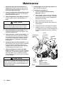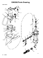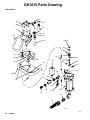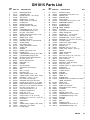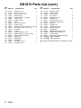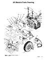
1
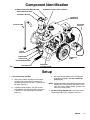
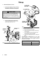
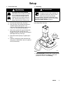
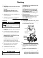
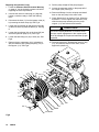
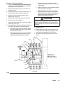
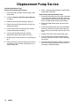
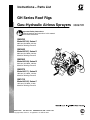
Instructions -- Parts List
GH Series Roof Rigs
Gas--Hydraulic Airless Sprayers
Important Safety Instructions
Read all warnings and instructions in this manual.
Save these instructions.
GH5030
Model 687100, Series C
4900 psi (33.8 MPa, 337 bar)
Maximum Working Pressure
GH3640
Model 687327, Series D
3600 psi (24.5 MPa, 245 bar)
Maximum Working Pressure
GH2560
Model 965168, Series B
2400 psi (16.6 MPa, 166 bar)
Maximum Working Pressure
GH2075
Model 965171, Series B
1800 psi (12.4 MPa, 124 bar)
Maximum Working Pressure
GH1015
Model 965165, Series C
1000 psi (0.70 MPa, 70 bar)
Maximum Working Pressure
GRACO INC. P.O. BOX 1441 MINNEAPOLIS, MN 55440--1441
Copyright 1999, Graco Inc. is registered to I.S. EN ISO 9001
9089c
308972R
Table of Contents
Warnings . . . . . . . . . . . . . . . . . . . . . . . . . . . . . . . . . . . . . . 2
Component Identification . . . . . . . . . . . . . . . . . . . . . . . . 5
Setup . . . . . . . . . . . . . . . . . . . . . . . . . . . . . . . . . . . . . . . . . 5
Flushing . . . . . . . . . . . . . . . . . . . . . . . . . . . . . . . . . . . . . . . 8
Operation . . . . . . . . . . . . . . . . . . . . . . . . . . . . . . . . . . . . 10
Maintenance . . . . . . . . . . . . . . . . . . . . . . . . . . . . . . . . . . 12
Troubleshooting . . . . . . . . . . . . . . . . . . . . . . . . . . . . . . . 13
Displacement Pump Service . . . . . . . . . . . . . . . . . . . .
Sprayer Parts Drawing . . . . . . . . . . . . . . . . . . . . . . . . .
Sprayer Parts List . . . . . . . . . . . . . . . . . . . . . . . . . . . . .
Accessories . . . . . . . . . . . . . . . . . . . . . . . . . . . . . . . . . .
Technical Data . . . . . . . . . . . . . . . . . . . . . . . . . . . . . . . .
Graco Warranty . . . . . . . . . . . . . . . . . . . . . . . . . . . . . . .
Graco Information . . . . . . . . . . . . . . . . . . . . . . . . . . . . .
16
18
34
37
37
38
38
Symbols
Warning Symbol
Caution Symbol
WARNING
CAUTION
This symbol alerts you to the possibility of serious
injury or death if you do not follow the instructions.
This symbol alerts you to the possibility of damage to
equipment if you do not follow the instructions.
WARNING
EQUIPMENT MISUSE HAZARD
Equipment misuse can cause the equipment to rupture or malfunction and result in serious injury.
INSTRUCTIONS
D This equipment is for professional use only.
D Read all instruction manuals, tags, and labels before operating the equipment.
D Use the equipment only for its intended purpose. If you are not sure, call your Graco distributor.
D Do not alter or modify this equipment. Use only genuine Graco parts.
D Check equipment daily. Repair or replace worn or damaged parts immediately.
D Do not exceed the maximum working pressure of the lowest rated system component. Refer to the
Technical Data on page 37 for the maximum working pressure of this equipment.
D Use fluids and solvents which are compatible with the equipment wetted parts. Refer to the Technical Data section of all equipment manuals. Read the fluid and solvent manufacturer’s warnings.
D Do not use hoses to pull equipment.
D Route hoses away from traffic areas, sharp edges, moving parts, and hot surfaces. Do not expose
Graco hoses to temperatures above 82_C (180_F) or below --40_C (--40_F).
D Do not lift pressurized equipment.
D Comply with all applicable local, state, and national fire, electrical, and safety regulations.
D Wear hearing protection when operating this equipment.
D Do not use 1,1,1--trichloroethane, methylene chloride, other halogenated hydrocarbon solvents or
fluids containing such solvents in pressurized aluminum equipment. Such use could result in a
chemical reaction, with the possibility of explosion.
2
308972
WARNING
SKIN INJECTION HAZARD
Spray from the gun, leaks or ruptured components can inject fluid into your body and cause extremely
serious injury, including the need for amputation. Fluid splashed in the eyes or on the skin can also
cause serious injury.
D Fluid injected into the skin may look like just a cut, but it is a serious injury. Get immediate surgical treatment.
D Do not point the gun at anyone or at any part of the body.
D Do not put your hand or fingers over the spray tip.
D Do not stop or deflect leaks with your hand, body, glove or rag.
D Do not “blow back” fluid; this is not an air spray system.
D Always have the tip guard and the trigger guard on the gun when spraying.
D Check the gun diffuser operation weekly. Refer to the gun manual.
D Be sure the gun trigger safety operates before spraying.
D Lock the gun trigger safety when you stop spraying.
D Follow the Pressure Relief Procedure on page 10 if the spray tip clogs and before cleaning,
checking or servicing the equipment.
D Tighten all fluid connections before operating the equipment.
D Check the hoses, tubes, and couplings daily. Replace worn or damaged parts immediately. Do not
repair high pressure couplings; you must replace the entire hose.
D Fluid hoses must have spring guards on both ends, to help protect them from rupture caused by
kinks or bends near the couplings.
TOXIC FLUID HAZARD
Hazardous fluid or toxic fumes can cause serious injury or death if splashed in the eyes or on the skin,
inhaled, or swallowed.
D Know the specific hazards of the fluid you are using.
D Store hazardous fluid in an approved container. Dispose of hazardous fluid according to all local,
state and national guidelines.
D Always wear protective eyewear, gloves, clothing and respirator as recommended by the fluid and
solvent manufacturer.
FUEL HAZARD
The fuel used in this unit is combustible and when spilled on a hot surface can ignite and cause a fire.
D Do not fill the fuel tank while the engine is running or hot.
EXHAUST HAZARD
The exhaust contains poisonous carbon dioxide which is colorless and odorless.
D Do not operate this equipment in a closed building.
308972
3
WARNING
FIRE AND EXPLOSION HAZARD
Improper grounding, poor ventilation, open flames or sparks can cause a hazardous condition and
result in a fire or explosion and serious injury.
D If there is any static sparking or you feel an electric shock while using this equipment, stop spraying immediately. Do not use the equipment until you identify and correct the problem.
D Provide fresh air ventilation to avoid the buildup of flammable fumes from solvents or the fluid
being sprayed.
D Keep the spray area free of debris, including solvent, rags, and gasoline.
D Disconnect all electrical equipment in the spray area.
D Extinguish all open flames or pilot lights in the spray area.
D Do not smoke in the spray area.
D Do not turn on or off any light switch in the spray area while operating or if fumes are present.
D Do not operate a gasoline engine in the spray area.
D Ground the sprayer to a true earth ground with the ground wire and clamp (supplied).
D Use only electrically conductive hoses.
MOVING PARTS HAZARD
Moving parts can pinch or amputate your fingers.
D Keep clear of all moving parts when starting or operating the sprayer.
D Before servicing the equipment, follow the Pressure Relief Procedure on page 10 to prevent the
equipment from starting unexpectedly.
NOTE: This is an example of the DANGER label on your sprayer. This label is available in other languages, free of
charge. See page 37 to order.
FIRE AND
EXPLOSION HAZARD
Spray painting, flushing or cleaning equipment with flammable
liquids in confined areas can result in fire or explosion.
Use outdoors or in extremely well ventilated areas. Ground
equipment, hoses, containers and objects being sprayed.
Avoid all ignition sources such as static electricity from plastic
drop cloths, open flames such as pilot lights, hot objects such as
cigarettes, arcs from connecting or disconnecting power cords
or turning light switches on and off.
Failure to follow this warning can result in death or serious injury.
SKIN INJECTION
HAZARD
Liquids can be injected into the body by high pressure airless
spray or leaks - especially hose leaks.
Keep body clear of the nozzle. Never stop leaks with any part of the
body. Drain all pressure before removing parts.Avoid accidental
triggering of gun by always setting safety latch when not spraying.
Never spray without a tip guard.
In case of accidental skin injection, seek immediate
“Surgical Treatment”.
Failure to follow this warning can result in amputation or serious
injury.
READ AND UNDERSTAND ALL LABELS AND INSTRUCTION MANUALS BEFORE USE
4
308972
Component Identification
HYDRAULIC RETURN LINE TO MOTOR
HYDRAULIC SUPPLY LINE TO MOTOR
MOTOR RESET BUTTON
HYDRAULIC MOTOR
HYDRAULIC
RESERVOIR
GASOLINE
FILL CAP
SUCTION TUBE
CHECK
VALVE
PRESSURE
HYDRAULIC
PUMP
DRAIN VALVE
DISPLACEMENT PUMP
Fig 1
SUCTION HOSE
9089d
PRESSURE
CONTROL KNOB
Setup
1. Connect the Hose and Gun
a. Remove the plastic cap plug from the outlet
tee and screw an accessory, conductive or
grounded spray hose onto the 1/4 npsm(f) outlet nipple. See Fig 1.
b. Connect a small diameter, 3 ft (0.9 m) whip
hose between the main hose and a spray gun,
if desired, for more flexible gun movement.
See Fig 1.
c.
Don’t use thread sealant on the swiveling nut
of the hose couplings, and don’t install the
spray tip yet.
NOTE: Use thread sealant on all male threads except at
swivel unions. Swivel unions are made to self-seal, and using thread sealant prevents the
swivel from turning freely.
2. Fill the Packing Nut/Wet Cup 1/3 full with Graco
Throat Seal Liquid (TSL), supplied. See Fig. 2.
308972
5
Setup
3. Check the Hydraulic Oil Level
a. Unscrew the hydraulic oil fill cap. See Fig 2.
The dipstick is attached to the cap. The oil
should be up to the full line on the dipstick.
GASOLINE
FILL CAP
OIL DIPSTICK
CAUTION
To prevent damage to the cooling system and
hydraulic pump, use only Graco Hydraulic Fluid,
169236 (5 gal./20 liter) or 207428 (1 gal/3.8 liter).
Other types of hydraulic oil may damage the hydraulic components.
b. Add oil as needed to the proper level. A
completely full hydraulic system contains
about 5 gallons (20 liters) of oil.
ENGINE OIL
FILL PLUG
7872b
Fig 3
PACKING
NUT/ WET
CUP
HYDRAULIC OIL
FILL CAP
4. Check the Engine Oil Level
a. Remove the dipstick. See Fig 3.
b. Check to be sure the oil is up to the full mark
on the dipstick.
c.
If oil is needed, see the chart below for the
recommended oil type and weight.
d. Crank case capacity with filter: 2.1 quarts (2.0
liters)
RECOMMENDED LUBRICATION OIL: Use a high
quality detergent oil of American Petroleum Institute
(API) service class SG or SH for regular use and for
breaking in a new engine.
GRADE OF OIL CHART
7871b
Fig 2
6
308972
SEASON OR TEMPERATURE
GRADE OF OIL
Spring, Summer, Autumn
SAE 10W--30
30_F to 0_, Winter
SAE 5W--20 or 5W--30
Setup
5. Fill the Fuel Tank
6. Grounding
WARNING
WARNING
FIRE AND EXPLOSION HAZARD
Fuel spilled on a hot surface can cause
a fire or explosion and serious bodily
injury and property damage. Shut off
engine and let it cool before filling the
tank. Carefully follow steps 5.a. to 5.c.,
below, being sure not to spill any fuel.
a. Close the fuel shutoff valve. See Fig 3.
FIRE AND EXPLOSION HAZARD
To reduce the risk of static sparking, fire
or explosion which can result in serious
bodily injury and property damage,
ground the sprayer, all system components, and
the object being sprayed as instructed under FIRE
OR EXPLOSION HAZARD on page 3.
Connect the ground wire and clamp (provided) to a
true earth ground. See Fig 4.
b. Use only clean, fresh, well-known brands of
unleaded regular grade gasoline. The
minimum octane requirements are 87 octane
in the U.S.A. and 96 octane elsewhere.
c.
Remove the gasoline fill cap and fill the tank.
Be sure the air vent in the fill cap is not
plugged so gasoline can flow to the carburetor,
then replace the cap. See Fig 3.
d. External fuel tank capacity: 6.0 gallons (22.7
liters)
e. Gasoline consumption at the maximum operating speed of 2900 RPM is about 1.3 gallons/
hour (4.9 liters/hour).
CLAMP
7873B
Fig 4
7. Flush the sprayer to remove the oil which was left
in the pump after factory testing to protect the
pump from corrosion. See Flushing.
308972
7
Flushing
When to Flush
1. New sprayer. Your new sprayer was factory tested
with lightweight oil which was left in to protect
pump parts from corrosion.
Before using oil- base paint, flush with mineral
spirits only.
Before using water- base paint, flush with
mineral spirits, followed by soapy water, then a
clean water rinse.
2. Changing colors. Flush with a compatible solvent
such as mineral spirits.
3. Changing from water--base to oil--base paint.
Flush with soapy water, then mineral spirits.
How to Flush
WARNING
SKIN INJECTION HAZARD
Follow the Pressure Relief Procedure
Warning on page 10. Remove the spray
tip before flushing.
4. Changing from oil--base to water--base paint.
Flush with mineral spirits, followed by soapy water,
then a clean water flush.
5. Storage.
Water- base paint: flush with water, then mineral
spirits and leave the pump, hose and gun filled
with mineral spirits. Follow the Pressure Relief
Procedure Warning, page 10.
Oil- base paint: flush with mineral spirits. Follow
the Pressure Relief Procedure Warning, page
10.
6. Startup after storage.
Before using water- base paint, flush out mineral
spirits with soapy water and then clean water.
When using oil- base paint, flush out mineral
spirits with fluid to be sprayed.
8. Turn and hold the ignition key to START until you
hear the engine “catch”, then release the key to RUN.
See Fig 5. If the engine does not start, open the
choke a little (move lever). If the engine floods, open
the choke all the way and try again.
1. Engage the gun safety latch. Remove the spray tip
from the gun.
CHOKE
2. Pour enough clean, compatible solvent to fill the
pump and hoses into a large, grounded metal pail.
ON/OFF
SWITCH
AIR FILTER
3. Place the suction tube into the pail or tilt the
sprayer back (it will support itself) and place the
pail under the pump. Then tilt the sprayer forward
to lower the pump into the pail.
4. Turn the pressure control knob counterclockwise
until all spring tension is relieved. You will be able
to feel it. The sprayer is now set at the lowest
pressure setting. Turning the knob further will
remove it. Tighten the knob locknut to set. See Fig
5.
5. Open the bypass valve. The valve lever will be
parallel to the body of the valve. See Fig 5.
PRESSURE
CONTROL
KNOB
BYPASS
VALVE
Fig 5
7874b
6. Attach fuel hose from tank to engine.
9. After the engine is warm, gradually open the choke
lever (move lever) and close the bypass valve.
See Fig 5.
7. Close the choke by moving the choke lever. See
Fig 5.
10. Point the gun into the grounded metal pail and hold
a metal part of the gun firmly against the pail.
CAUTION
The bypass valve must be opened when starting the
sprayer to prevent damaging the starter.
8
308972
NOTE: To save the fluid in the pump and hose, trigger
the gun into the paint container or a separate
clean container. At the same time, slowly turn the
pressure control knob clockwise just enough to
start the pump. When solvent appears, release
the trigger and continue as below.
Flushing
WARNING
FIRE AND EXPLOSION HAZARD
To reduce the risk of static sparking and
splashing when flushing, always remove
the spray tip from the gun and hold a
metal part of the gun firmly to the side of a
grounded metal pail.
11. Making firm metal-to-metal contact, hold the gun
firmly to the side of the grounded solvent pail.
Trigger the gun. At the same time, slowly turn the
pressure control knob clockwise just enough to
start the pump.
12. Circulate the solvent until the system is thoroughly
flushed.
13. Release the trigger and engage the gun safety
latch.
14. If you are going to start spraying, place the
pump or suction tube into the supply container.
Follow the Pressure Relief Procedure on page
10. Engage the gun safety latch until you are ready
to prime the pump. See Step 3, page 9.
15. If you are going to store the sprayer, be sure
your final flush is with an oil--based solvent, such
as mineral spirits. Remove the suction tube or
pump from the solvent pail. Follow the Pressure
Relief Procedure on page 10. Engage the gun
safety latch, but leave the drain valve open.
308972
9
Operation
Pressure Relief Procedure
WARNING
SKIN INJECTION HAZARD
The system pressure must be manually
relieved to prevent the system from
starting or spraying accidentally. Fluid
under high pressure can be injected through the
skin and cause serious injury. To reduce the risk of
an injury from injection, splashing fluid, or moving
parts, follow the Pressure Relief Procedure
whenever you:
D
D
D
D
are instructed to relieve the pressure,
stop spraying,
check or service any of the system equipment,
install or clean the spray tip.
1. Engage the gun safety latch.
2. Starting the Sprayer
a. Open the bypass valve to make startup easier.
In the open position, the valve lever is parallel
to the body of the valve. See Fig 6. Close the
filter drain valve.
b. Turn the pressure control knob counterclockwise until all spring tension is relieved. You will
be able to feel it. The sprayer is now set at the
lowest pressure setting. Turning the knob further will cause it to fall off.
c. Attach fuel hose from tank.
d. If the engine is cold, close the choke by moving the choke lever. See Fig 6.
3. Turn and hold the ignition key to START until you
hear the engine “catch”, then release the key to
RUN. See Fig 6. If the engine does not start,
open the choke a little (move choke lever). If the
engine floods, open the choke all the way and try
again.
e. After the engine is warm, gradually open the
choke lever (move choke lever) and close the
bypass valve. See Fig 6.
2. Open the bypass valve.
3. Turn the ignition key to OFF.
CHOKE
4. Disengage the gun safety latch. Hold a metal part
of the gun firmly to the side of a grounded metal
pail, and trigger the gun to relieve pressure.
ON/OFF
SWITCH
AIR FILTER
5. Engage the gun safety latch.
PRESSURE
CONTROL
KNOB
6. Open the pressure drain valve, having a container
ready to catch the drainage. Leave the valve open
until you are ready to spray again.
If you suspect that the spray tip or hose is completely
clogged, or that pressure has not been fully relieved after
following the steps above, wrap a rag around the tip
guard retaining nut or hose end coupling and VERY
SLOWLY loosen the part to relieve pressure gradually,
then loosen completely. Now clear the tip or hose.
1. Prepare the Fluid
a. Prepare the fluid according to the fluid manufacturer’s recommendations.
b. Place the pump or suction tube into the fluid
container.
10
308972
BYPASS
VALVE
Fig 6
7874b
NOTE: In cold weather, run the engine for about 15
minutes with the bypass valve open before
starting the displacement pump, to help avoid
hydraulic motor stalling.
f. Follow the Pressure Relief Procedure
Warning on page 10, to shut off the sprayer.
WARNING
To stop the engine in an emergency, turn OFF
the ignition key. Close the bypass valve if possible.
See Fig 6. Then follow the Pressure Relief Procedure Warning on page 10.
Operation
If the motor stalls during operation, turn OFF the ignition key. With your hand, firmly press straight down on
the motor reset button. Now try to restart the sprayer. If
it will not start, refer to the separate motor manual,
307158.
CAUTION
Never use a hammer to depress the reset button, as
it could cause serious internal motor damage.
4. Prime the Pump
a. Be sure the gun safety latch is engaged.
b. Don’t install the spray tip yet!
c. If the engine has not been started, follow the
procedure in Step 2., page 10.
d. Disengage the gun safety latch.
e. Point the gun into a grounded metal pail and
hold a metal part of the gun firmly against the
pail. See the WARNING below.
f. Squeeze the trigger and slowly turn the pressure control knob clockwise just enough to
start the pump. See Fig 6.
g. Operate the pump until all air is purged from
the pump and hoses and the fluid is flowing
freely from the gun.
h. Release the trigger and engage the safety
latch.
i. Turn the pressure control knob counterclockwise until all spring tension is relieved. You will
be able to feel it. The sprayer is now at the
lowest pressure setting. Turning the knob
further will remove it.
j. Follow the Pressure Relief Procedure on
page 10. Then install the spray tip in the gun
as instructed in the separate gun or tip instruction manual. If you are using the RAC IV
supplied with this sprayer, see manual 308644.
5. Adjusting the Pressure
a. Turn the pressure control knob clockwise to
increase and counterclockwise to decrease the
pressure. Tighten the knob locknut to set.
b. Always use the lowest pressure that is necessary to completely atomize the fluid.
CAUTION
Operating the sprayer at a higher pressure than
necessary wastes fluid, causes early tip wear, and
shortens the sprayer life.
c.
If more coverage is needed, use a larger tip
rather than increasing the pressure.
d. Check the spray pattern. The tip size and
angle determines the pattern width and flow
rate. See the separate manual received with
your gun.
CAUTION
The engine throttle has been set to a maximum of
3000 RPM. The sprayer warranty will be voided and
the hydraulic pump life shortened if this adjustment is
changed.
6. Cleaning a Clogged Tip
WARNING
SKIN INJECTION HAZARD
To reduce the risk of a fluid injection
injury, NEVER hold your hand, body or a
rag in front of the spray tip when
cleaning or checking for a cleared tip. To reduce
the risk of a fire or explosion, always hold the gun
firmly against the side of a grounded metal waste
container when checking to see if the tip was
cleared or when using a self--clearing tip.
a. Follow the Pressure Relief Procedure
Warning on page 10.
b. Clean the front of the tip frequently during the
day to keep the fluid from building up and clogging the tip. To clean, and to clear a tip if it
clogs, refer to your separate gun instruction
manual. If you are using the RAC IV tip guard
and SwitchTip, refer to manual 308644.
7. Shutting Off the Sprayer
a. Whenever you stop spraying, even for a short
break, follow the Pressure Relief Procedure
Warning on page 10.
b. Clean the tip and gun as recommended in your
separate gun or tip manual.
c.
Flush the sprayer at the end of each work day
if using water--based fluid or if it could harden
in the sprayer over night. See FLUSHING,
page 8. Use a compatible solvent to flush,
then fill the pump and hoses with solvent such
as mineral spirits to help prevent pump corrosion. Relieve pressure!
d. For long term shutdown or storage, always fill
the sprayer with mineral spirits to prevent
pump corrosion. Relieve pressure!
8. Adjusting the Intake Valve Ball Travel.
a. The pump is set to handle medium volume,
low viscosity fluid. To adjust the pump for
higher flow or heavier viscosity fluid, disassemble the intake valve as instructed in the
appropriate pump manual listed in the parts list
and move the ball stop pin to a higher set of
holes. This increases the ball travel.
308972
11
Maintenance
1. Always stop the pump at the bottom of its
stroke when you take a break and at the end of
the day. This helps keep fluid from drying on the
rod and damaging the packings.
2. Keep the displacement pump packing nut/wet
cup 1/3 full of TSL at all times. The TSL helps
protect the packings and rod.
3. Check the tightness of the packing nut daily. It
should be tight enough to stop leakage but no
tighter.
CAUTION
Proper engine and hydraulic oil level is important to
prevent costly damage to the sprayer. Check it as
often as recommended in Steps 4 and 5., below.
8. Change engine oil and filter every 100 hour of
use. Use 30W detergent oil.
9. To change the hydraulic oil:
a. Follow the Pressure Relief Procedure
Warning on page 10.
b. Place a waste container under the drain plug
of the hydraulic reservoir. See Fig 7. Unscrew
the plug and drain the reservoir. Reinstall the
plug before proceeding.
c.
d. Remove the return line filter and install a new
filter assembly.
e. Inspect the inlet filter and replace it if needed.
f.
4. Check the hydraulic oil level weekly. The oil
must be up to the top mark on the dipstick. Use
only Graco Hydraulic Oil.
5. Check the engine oil level at least weekly. The
oil must be up to the FULL mark on the dipstick.
The engine should not use more than one ounce
of oil per hour of operation. Consult the engine
manual, supplied, for additional recommended
maintenance.
Remove the nuts and reservoir cover.
Install the reservoir cover and nuts. Then pour
in five gallons (19 liters) of Graco Hydraulic Oil
through the intake filter. See Fig 7. Install the
fill cap.
NUTS
HYDRAULIC
OIL FILL
CAP
COVER
INLET
FILTER
6. Inspect the return line filter frequently for clogging. Replace it after every 500 hours of operation
or every 6 months, whichever comes first. A
clogged or worn out filter reduces filter capability
and will damage the hydraulic pump.
7. Change the hydraulic oil after every 2000
hours of operation or every 12 months, whichever
comes first. For continuous operation in temperatures above 85_F (30_C), change the oil after
every 1000 hours or 6 months of use. See Step 9.
for the procedure.
CAUTION
Cleanliness is essential when servicing the hydraulic
system. Use special care to avoid getting dust or dirt
into the hydraulic system to prevent damage to the
hydraulic components.
12
308972
RETURN
LINE
FILTER
Fig 7
HYDRAULIC OIL
DRAIN
PLUG LOCATED
UNDER RESERVOIR
ENGINE
OIL
FILL PLUG
Troubleshooting
WARNING
SKIN INJECTION HAZARD
To reduce the risk of serious injury,
whenever you are instructed to relieve
pressure, follow the Pressure Relief
Procedure on page 10.
Check everything in the troubleshooting chart before disassembling the sprayer.
PROBLEM
CAUSE
SOLUTION
Gas engine doesn’t work properly.
Consult engine manual, supplied.
Gas engine will not start.
Check battery.
Gas engine operates, but
displacement pump doesn’t
operate.
Hydraulic motor stalled.
Turn the ignition key to OFF. Firmly press
straight down on motor reset button. Restart
sprayer, see page 10. If it doesn’t start, see
manual 307158.
Pressure setting too low.
Increase pressure. See page 11.
Displacement pump outlet filter (if
used) is dirty or clogged.
Clean the filter.
Tip or tip filter (if used) is clogged.
Remove tip and/or filter and clean.
Hydraulic fluid too low.
Shut off sprayer and add fluid immediately*. See
page 5.
Hydraulic pump worn or damaged.
Return sprayer for repair.
Hydraulic motor worn or damaged.
Return sprayer for repair.
Displacement pump rod seized by
dried paint.
Service pump. See pump manual.
Displacement pump operates, but
output is low on upstroke.
Piston ball check not seating properly.
Service piston ball check. See pump manual.
Piston packings worn or damaged.
Replace packings. See pump manual.
Displacement pump operates but
output is low on downstroke and/
or on both strokes.
Piston packings worn or damaged.
Replace packings. See pump manual.
Intake valve ball check not seating
properly.
Service intake valve ball check. See pump
manual.
Paint leaks into wetcup.
Loose wet--cup.
Tighten just enough to stop leakage.
Throat packings worn or damaged.
Replace packings. See pump manual.
Excessive leakage around
hydraulic motor piston rod wiper.
Piston rod seal worn or damaged.
Replace these parts. See manual 307158.
Fluid delivery is low.
Pressure setting too low.
Increase pressure. See page 11.
Displacement pump outlet filter (if
used) is dirty or clogged.
Clean filter.
Hydraulic pump is worn or damaged.
Return sprayer for repair.
Hydraulic motor is worn or damaged.
Return sprayer for repair.
Large pressure drop in fluid hose.
Use larger diameter hose.
The sprayer overheats.
Cooler or blower is worn or damaged.
Replace. See page 15.
Spitting from gun.
Air in fluid pump or hose.
Check for loose connections on siphon
assembly, tighten, then reprime pump.
Fluid supply is low or empty.
Refill supply container.
*Check hydraulic fluid level often. Do not allow it to become too low. Use only Graco approved hydraulic fluid. See pages 6 and 37.
308972
13
8. Pull the pump straight off the pump support.
Replacing the Hydraulic Pump
1. Follow the Pressure Relief Procedure Warning
on page 10. Let the hydraulic system cool before
beginning the service procedure.
9. Loosen the setscrews (108) on the pump half of
the coupler (109). See Fig 9.
10. Remove all fittings from the old pump and install
them on the new pump in the same order.
2. Unscrew the reservoir drain plug (51, page 36),
having a container ready to catch the draining
fluid.
11. Check Dimension A as shown in Fig 9. When the
dimension is correct, tighten the setscrews (108),
slide the new pump assembly onto the pump
support (117) and recheck the dimension.
3. Disconnect the hose (7) from the bypass valve (9)
by loosening the hose clamp (8). See Fig 8.
4. Loosen the hose clamp (8) and pull the hose (85)
off the hose insert (5) near the elbow (3). See Fig
8.
CAUTION
The correct coupling dimension is critical to avoid
improper coupler engagement to the coupler spider
which will damage the coupler and make the sprayer
inoperable.
5. Loosen the hose clamp (54) on the hose (53) just
above the hydraulic pump (107). See Fig 8.
6. Loosen the tube fitting nut (18) of hose (22). See
Fig 8.
7. Remove the two capscrews (150), lockwashers
(66) and washers (64) holding the pump (107) to
the support (117). See Fig 8.
3
152
5
8
85
12. Reconnect the hoses. Reinstall the reservoir plug
(51), and refill the reservoir with clean, Graco
approved hydraulic oil.
113
112
53
117
54
52
4
7
8
7876c
9
108
114
22
18
Fig 8
14
308972
107
150,66,64
115
49,66
109
c.
Replacing the Cooler and Blower
1. Follow the Pressure Relief Procedure Warning
on page 10. Let the hydraulic system cool before
beginning the service procedure.
Pull the pump support and blower off far
enough for the blower to fall out of the bottom
of the housing.
d. Install a new blower. Secure the pump support
(117) to the engine. See Fig 8.
2. Remove the hydraulic pump as instructed in the
previous section.
e. Check Dimension A as shown in Fig 9 and
tighten the coupler setscrews (108). Butt the
blower hub up to the coupler half, keeping the
blower in full contact with the coupler, and
tighten the blower setscrews (B).
3. Disconnect the cooler to reservoir return hose (7.)
by loosening the hose clamp (8). See Fig 8.
4. Remove the cooler capscrews (49) and lockwashers (66). See Fig 8.
CAUTION
5. Remove the fan guard (23, page 36). See Fig 8.
6. Pull the cooler (115) straight out.
The correct coupling dimension is critical to avoid
improper coupler engagement to the coupler spider
which will damage the coupler and make the sprayer
inoperable.
7. Inspect the rubber pad (116) for wear and replace
if necessary. See Fig 9.
8. Inspect the blower wheel (114) for wear. See Fig 8.
If it needs to be replaced, follow Steps 8a--8e.
9. Install the cooler.
a. Unscrew the setscrews (108) from the engine
half of the coupler (109). Unscrew the blower
setscrews (B). See Fig 9.
10. Fold the flaps of the pad (116) toward the cooler
fins and install the fan guard (23, page 36), capscrews (49) and lockwashers (66). See Fig 8.
b. Remove the capscrews (112) and lockwashers
(113) holding the pump support (117) to the
engine and pull the support off. See Fig 8.
11. Reinstall the hydraulic pump and reconnect all
hoses.
ENGINE
108
B
115
23
117
A
DIMENSION A
0.05 in. ± 0.010
(1.27 mm ± --0.254)
A
107
109
108
116
TOP VIEW
Fig 9
308972
15
Displacement Pump Service
210208 Displacement Pump
Disconnect the Displacement Pump
1. Flush the pump if possible. Stop the pump on the
down stroke.
2. Follow the Pressure Relief Procedure Warning
on page 10.
3. Reference Roof Rig Parts Drawings, page 30.
4. Remove the suction tube and fluid hose from the
displacement pump.
5. Unscrew the three tie rod locknuts (48). See appropriate sprayer parts drawing.
6. Unscrew the shouldered nut (35). Pull the
displacement pump (46) off the tie rods (47).
9. Refer to separate pump manual for displacement
pump repair instructions.
Reconnecting the Displacement Pump
1. Screw the connecting rod (91) into the connecting
rod coupling (36, page 30) and replace the lower
cotter pin (89). Screw the jam nut (90) all the way
down. See appropriate sprayer parts drawing.
2. Mount the displacement pump (46) onto the tie
rods (47).
3. Screw the shouldered nut (35) onto the hydraulic
motor (29). Screw the tie rod locknuts (48) onto
the tie rods (47) and torque to 35--50 ft-lb (47--68
N.m).
4. Reattach the hoses to the displacement pump.
7. Screw the jam nut (90) up onto the connecting rod
(91).
5. If the grounding wire was disconnected before
service, be sure to reconnect it before operating
the sprayer.
8. Remove the lower cotter pin (89) and unscrew the
connecting rod (91) from the connecting rod coupling (36, page 30).
6. Start the pump and operate it slowly to check the
tie rods for binding. Adjust the tie rod locknuts, if
necessary to eliminate binding.
16
308972
Displacement Pump Service
237510 and 222801 Displacement Pumps
Disconnecting the Displacement Pump
1. Flush the pump, if possible. Stop the pump at the
bottom of its stroke.
Reconnecting the Displacement Pump
1. Make sure coupling nut (170) and coupling collars
(80) are in place on displacement rod (Ref. 29).
WARNING
To reduce the risk of serious injury whenever you
are instructed to relieve pressure, always follow the
Pressure Relief Procedure on page 10.
2. Relieve the pressure.
3. Reference Roof Rig Parts Drawings, pages 18
through 27.
4. Disconnect the air or hydraulic hose and the fluid
hose. Plug all hydraulic hoses immediately, to
prevent contamination of the hydraulic system.
5. Disconnect the displacement pump (46) from the
motor (29) as follows. Note the relative position of
the pump fluid outlet (81) to the hydraulic inlet (76)
of the motor. If the motor does not require servicing, leave it attached to its mounting.
2. Use at least two people to hold the displacement
pump while another reconnects it to the motor (see
the preceding CAUTION). Orient the pump fluid
outlet (81) to the hydraulic inlet (76) as was noted
in step 5 under Disconnecting the Displacement
Pump. Position the displacement pump (46) on
the tie rods (47).
3. Screw the nuts (48) onto the tie rods (47) and
torque to 81--89 N.m (60--66 ft-lb).
4. Screw coupling nut onto motor shaft (Ref. 29),
loosely. Hold the motor shaft flats with a wrench to
keep it from turning. Use an adjustable wrench to
tighten the coupling nut. Torque to 196--210 N.m
(145--155 ft-lb).
CAUTION
Use at least two people when lifting, moving, or disconnecting the pump. This pump is too heavy for one
person. Support the displacement pump while it is
being disconnected, to prevent it from falling and
causing injury or property damage.
5. Reconnect all hoses. Reconnect the ground wire if
it was disconnected. Fill the packing nut (2) 1/3 full
of Graco Throat Seal Liquid or compatible solvent.
If the pump is mounted on a cart, slowly tip the cart
backward until the handle rests on the ground, then
disconnect the displacement pump.
6. Turn on the hydraulic power supply. Open the
hydraulic return line valve first, then the supply line
valve. Run the pump slowly to ensure proper
operation.
6. Using an adjustable wrench (or hammer and
punch), unscrew the coupling nut (170) from the
motor shaft ( Ref. 29). Take care not to lose or
drop the coupling collars (80).
7. Hold the tie rod flats with a wrench to keep the
rods from turning. Unscrew the nuts (48) from the
tie rods (47). Carefully remove the displacement
pump (46) from the motor (29).
8. Refer to separate manual listed in parts list for
displacement pump service. To service the hydraulic motor, refer to the separate motor manual,
supplied.
WARNING
To reduce the risk of serious injury whenever you
are instructed to relieve pressure, always follow the
Pressure Relief Procedure on page 10.
7. Before returning the pump to production, relieve
the pressure and retorque the packing nut (2) to
136--149 N.m (100--110 ft-lb).
308972
17
GH5030 Parts Drawing
79
29
125
31
76
82
77
34
65
22
Ref 29
80
100
103
32
143
101
47
170
70
49
177
104
48
38
Ref 26
84
46
81
166
39
127
144
43
44
45
9086B
Model 687100
18
308972
GH5030 Parts List
REF
NO. PART NO.
1
2
3
4
5
7
8
9
10
11
12
13
14
15
16
17
18
19
20
21
22
23
24
25
26
27
28
29
30
31
32
33
34
35
36
37
38
39
40
41
43
44
45
46
107074
106114
107053
107128
107050
178859
102473
210658
165472
106039
106123
100018
100321
188344
103475
158491
107052
115753
107069
101354
513575
178751
179714
100213
217469
101578
100214
217022
177755
110838
625057
158586
177652
168210
168211
500566
111337
100505
107129
107073
513631
513549
116976
570183*
47
48
49
50
51
52
53
54
55
56
57
58
59
60
198592
101712
100101
104444
104126
107049
178791
101818
178773
177641
177570
113951
107068
15C713
DESCRIPTION
QTY
BREATHER, fill cap
1
STRAINER, inlet
1
ELBOW, pipe, 90_, 1/2 x 3/8 npt
1
TEE, service
1
INSERT, hose, 1/2 npt(f)
3
HOSE, rubber, 5 in. (125 mm)
1
CLAMP, hose
6
VALVE, ball 3/8 npt(m)
1
ELBOW, pipe, 90_, 3/8 npt(f)
1
WHEEL
2
CAPSCREW, hex hd, 1/2 x 4 in.
4
LOCKWASHER, spring, 1/2 in.
4
NUT, hex, 1/2 in. thread
4
NIPPLE, pipe, reducing, 3/8 x 1/2 npt
1
TEE, pipe, 1/2 npt(f)
1
NIPPLE, short, 1/2 npt
1
FITTING, tube, flared
1
BATTERY, 12 volt, “L” style terminals
1
CLAMP, battery
1
PIN, straight, spring
2
HOSE, coupled 3/4 in. X 30 in.
1
GUARD, fan
1
SPACER
1
NIPPLE, pipe, 3/8 npt x 3 in.
1
FRAME, pump
1
CAPSCREW, hex head, 8--32 x 0.38 in. 4
LOCKWASHER, spring, 5/16 in.
19
MOTOR, hydraulic, Manual 307158
1
LABEL, identification
1
NUT, lock, 5/16--18
6
Bracket, hydraulic motor
2
REDUCER, 1 in.
2
HANDLE
1
NUT, shouldered
1
COUPLING, connecting rod
1
TEE
2
TEE, 1 in. npt(f)
1
BUSHING, pipe
1
BOLT, carriage, 5/16 in. x 1 in.
1
CABLE, battery, positive, 26 in., 6 awg
1
KIT, suction, GH roofing rig
1
ADAPTER, male quick disconnect
1
ELBOW, street, pipe, 90_
1
PUMP, displacement;
L220C1 220cc 900 std
1
ROD, Tie, 14.59 in. shoulder to shoulder 3
NUT, lock, type “E” 5/8 in.-- 11
3
Screw, Hex HD 3/8--16 X 1 in.
5
O--RING, fluoroelastomer
1
PLUG, box, 3/4 in.
1
INSERT, hose, 3/4 npt(f)
1
HOSE, suction, 1 in. ID, 3’ (9.9 m)
1
CLAMP, hose, 13/16 in. to 1--1/2 in. OD 2
LEG, frame
1
WASHER, flat
2
AXLE
1
CABLE, battery, negative, 8 in., 6 awg
1
HOOK, bolt, 1/4 in. thread
1
PLATE, engine
1
REF
NO. PART NO.
61
62
63
64
65
67
68
70
71
72
73
74
75
76
77
78
79
80
81
82
83
84
85
86
87
88
89
90
91
92
93
94
95
96
97
98
99
100
101
102
103
104
105
106
107
108
109
110
111
112
113
114
115
116
117
118
119
120
216141
100468
104766
100023
177765
100678
803444
244819
218125
185951Y
184471
100188
177807
106053
513574
107127
620188
197341
157785
105430
15C712
158586
178795
158555
177808
178935
100103
101936
168212
158674
107125
105429
178750
178794
500054
107067
100086
106212
196666
112179
112798
219099
100187
178872
100421
106063
605358
113287
107143
100052
178792
178788
178861
178786
802277
100016
100011
DESCRIPTION
QTY
SUPPORT, engine
1
CAPSCREW, hex hd, 3/8 x 1.5 in.
4
MOUNT, motor
4
WASHER, 3/8 in.
18
PLUG, handle
2
CAPSCREW, hex hd, 5/16 X 1.75 in.
4
DAMPENER, pulsation
1
COUPLING, assy
2
RESERVOIR KIT
1
LABEL, DANGER
1
COUPLER
1
NUT, heavy hex, 5/16--18 unc--2a
11
LABEL, identification
1
ELBOW, 90_, 1--1/16 in. thread
1
HOSE, coupled 1 in. X 20 in.
1
ADAPTER, male, 1--5/16 in. x 3/4 in.
1
ADAPTER, 1 in. (m) x3/4 x 1/2 x 3/8 (f)
1
COLLAR coupling
2
UNION 3/4 in. (M)--(F) Straight
1
NUT, seal, 1 in. npt
1
SHIELD, heat
1
BUSHING, 3/4 in. X 1 in. npt
1
HOSE, cooler, 0.625 in., 10.5 in. lg
1
NIPPLE
1
LABEL, identification
1
LABEL, caution
1
PIN, cotter, 0.125 in. dia, 1.5 in. long
2
NUT, hex jam, 3/4 in.--10
1
ROD, connecting
1
PACKING, o--ring, buna--n
1
ELBOW, 90_ street, 3/4 npt(m)
1
NUT, seal, 3/4 npt
1
FITTING, return, 1 in. npt(m) x 3/4 npt(f) 1
FILTER, fluid
1
BUSHING, hex hd
1
O--RING, buna--n
1
WASHER
3
SCREW, cap
2
LABEL, ID
1
SCREW, mach
3
SCREW, mach, hex washer hd, 8 x 3/8 in. 1
LABEL, identification
1
KNOB, pump
1
NUT, hex, 5/16 in.
1
PUMP, vane, hydraulic
1
SETSCREW, 5/16 in. X 3/8 in.
2
COUPLER
2
KEY, 1/4 in.
1
ENGINE, 18 HP, OHC
1
CAPSCREW, sch, 7/16 x 1.25 in.
4
LOCKWASHER, spring, 7/16 in.
4
BLOWER
1
COOLER
1
PAD
2
SUPPORT, pump
1
CAPSCREW, hex hd, 5/16 x 1.5
4
LOCKWASHER, spring, 1/4 in.
3
WING NUT, 1/2 in.
2
308972
19
GH5030 Parts List (cont.)
REF
NO. PART NO.
121
122
123
124
125
127
130
131
132
137
138
139
140
141
142
143
144
145
150
166
167
168
169
107139
100015
178787
217286
196845
180233Y
156172
206994
185016
100004
107032
184470
109213
183574
183575
237686
245143
110755
159841
101566
110838
191958
191959
20
308972
DESCRIPTION
QTY
BOLT, carriage, 1/4 x 1 in.
1
NUT, hex, 1/4--10 unc
1
SHELF, battery
1
CHECK VALVE, 1 in. npt (fbe)
1
LABEL, ID, top
1
LABEL, warning
2
UNION
1
TSL, 8 oz. not shown
1
LABEL, Caution
1
CAPSCREW, hex hd, 3/8--16 in. x 1.25 in. 2
ELBOW, 90_ street, 3/8 npt (m x f)
1
COUPLER
1
O--RING
1
HOSE, rubber tube, 4.5 in.
1
NIPPLE, barbed hose, 3/8--18 npt(f)
1
GROUND WIRE & CLAMP
1
VALVE, pressure, bleed
1
WASHER, flat
2
ADAPTER
1
NUT, Nylock 3/8--16
LOCKNUT, 5/16 in.
4
BRACKET, switch
1
GUARD, muffler
1
REF
NO. PART NO.
170
171
172
173
176
177
181
180
182
183
184
185
186
187
188
189
190
197340
113819
100022
100016
070401
244820
191863
195516
113372
192228
801971
801959
801958
118423
238681
189285Y
290386Y
DESCRIPTION
QTY
NUT, Coupling
NUT, 1/4 in.
SCREW, cap, 1/4 in.
WASHER, lock
TUBING, electrical, 13 in.
CLIP, hairpin, with lanyard
GUARD, hose
SPACER
COUPLING, fuel line
BRACKET, gas line
CLAMP, hose
PROTECTOR, terminal, black
PROTECTOR, terminal, red
COVER, debris
FUEL TANK ASSEMBLY, 6 gallon
LABEL, DANGER
LABEL, WARNING
1
2
2
2
1
1
1
4
1
1
2
1
1
1
1
1
1
Y DANGER and WARNING labels are available at no charge.
* Packing Repair Kit 244852 includes throat and piston
packings. Refer to Manual 311762. Reference pump
L220C1 (220cc 900 std).
GH3640 Parts Drawing
Model 687327
29
79
125
31
76
82
77
34
65
22
Ref 29
80
100
103
143
32
101
47
170
70
49
177
104
48
Ref 26
38
84
46
81
166
39
127
144
43
44
45
9086B
308972
21
GH3640 Parts List
REF
NO. PART NO.
1
2
3
4
5
7
8
9
10
11
12
13
14
15
16
17
18
19
20
21
22
23
24
25
26
27
28
29
30
31
32
33
34
35
36
37
38
39
40
41
43
44
45
46
107074
106114
107053
107128
107050
178859
102473
210658
165472
106039
106123
100018
100321
188344
103475
158491
107052
115753
107069
101354
513575
178751
179714
100213
217469
101578
100214
217022
177755
110838
625057
158586
177652
168210
168211
500566
111337
100505
107129
107073
513631
513549
116976
687329*
47
48
49
50
51
52
53
54
55
56
57
58
59
198592
101712
100101
104444
104126
107049
178791
101818
178773
177641
177570
113951
107068
22
308972
DESCRIPTION
QTY
BREATHER, fill cap
1
STRAINER, inlet
1
ELBOW, pipe, 90_, 1/2 x 3/8 npt
1
TEE, service
1
INSERT, hose, 1/2 npt(f)
3
HOSE, rubber, 5 in. (125 mm)
1
CLAMP, hose
6
VALVE, ball 3/8 npt(m)
1
ELBOW, pipe, 90_, 3/8 npt(f)
1
WHEEL
2
CAPSCREW, hex hd, 1/2 x 4 in.
4
LOCKWASHER, spring, 1/2 in.
4
NUT, hex, 1/2 in. thread
4
NIPPLE, pipe, reducing, 3/8 x 1/2 npt
1
TEE, pipe, 1/2 npt(f)
1
NIPPLE, short, 1/2 npt
1
FITTING, tube, flared
1
BATTERY, 12 volt, “L” style terminals
1
CLAMP, battery
1
PIN, straight, spring
2
HOSE, coupled 3/4 in. X 30 in.
1
GUARD, fan
1
SPACER
1
NIPPLE, pipe, 3/8 npt x 3 in.
1
FRAME, pump
1
CAPSCREW, hex head, 8--32 x 0.38 in. 4
LOCKWASHER, spring, 5/16 in.
19
MOTOR, hydraulic, Manual 307158
1
LABEL, identification
1
NUT, lock, 5/16--18
6
Bracket, hydraulic motor
2
REDUCER, 1 in.
2
HANDLE
1
NUT, shouldered
1
COUPLING, connecting rod
1
TEE
2
TEE, 1 in. npt(f)
1
BUSHING, pipe
1
BOLT, carriage, 5/16 in. x 1 in.
1
CABLE, battery, positive, 26 in., 6 awg
1
KIT, suction, GH roofing rig
1
ADAPTER, male quick disconnect
1
ELBOW, street, pipe, 90_
1
PUMP, displacement;
L290C1 290cc 1200 std
1
ROD, Tie, 14.59 in. shoulder to shoulder 3
NUT, lock, type “E” 5/8 in.-- 11
3
Screw, Hex HD 3/8--16 X 1 in.
5
O--RING, fluoroelastomer
1
PLUG, box, 3/4 in.
1
INSERT, hose, 3/4 npt(f)
1
HOSE, suction, 1 in. ID, 3’ (9.9 m)
1
CLAMP, hose,13/16 in. to 1--1/2 in. OD
2
LEG, frame
1
WASHER, flat
2
AXLE
1
CABLE, battery, negative, 18 in., 6 awg 1
HOOK, bolt, 1/4 in. thread
1
REF
NO. PART NO.
60
61
62
63
64
65
67
68
70
71
72
73
74
75
76
77
78
79
80
81
82
83
84
85
86
87
88
89
90
91
92
93
94
95
96
97
98
99
100
101
102
103
104
105
106
107
108
109
110
111
112
113
114
115
116
117
118
119
15C713
216141
100468
104766
100023
177765
100678
803444
244819
218125
185951Y
184471
100188
177807
106053
513574
107127
620188
197341
157785
105430
15C712
158586
178795
158555
177808
178935
100103
101936
168212
158674
107125
105429
178750
178794
500054
107067
100086
106212
196665
112179
112798
219099
100187
178872
100421
106063
605358
113287
107143
100052
178792
178788
178861
178786
802277
100016
DESCRIPTION
QTY
PLATE, engine
1
SUPPORT, engine
1
CAPSCREW, hex hd, 3/8 x 1.5 in.
4
MOUNT, motor
4
WASHER, 3/8 in.
18
PLUG, handle
2
CAPSCREW, hex hd, 5/16 X 1.75 in.
4
DAMPENER, pulsation
1
COUPLING, assy
2
RESERVOIR KIT
1
LABEL, DANGER
1
COUPLER
1
NUT, heavy hex, 5/16--18 unc--2a
11
LABEL, identification
1
ELBOW, 90_, 1--1/16 in. thread
1
HOSE, coupled 1 in. X 20 in.
1
ADAPTER, male, 1--5/16 in. x 3/4 in.
1
ADAPTER, 1 in. (m) x3/4 x 1/2 x 3/8 (f)
1
COLLAR coupling
2
UNION 3/4 in. (M)--(F) Straight
1
NUT, seal, 1 in. npt
1
SHIELD, heat
1
BUSHING, 3/4 in. X 1 in. npt
1
HOSE, cooler, 0.625 in., 10.5 in. lg
1
NIPPLE
1
LABEL, identification
1
LABEL, caution
1
PIN, cotter, 0.125 in. dia, 1.5 in. long
2
NUT, hex jam, 3/4 in.--10
1
ROD, connecting
1
PACKING, o--ring, buna--n
1
ELBOW, 90_ street, 3/4 npt(m)
1
NUT, seal, 3/4 npt
1
FITTING, return, 1 in. npt(m) x 3/4 npt(f) 1
FILTER, fluid
1
BUSHING, hex hd
1
O--RING, buna--n
1
WASHER
3
SCREW, cap
2
LABEL, ID
1
SCREW, mach
3
SCREW, mach, hex washer hd, 8 x 3/8 in. 1
LABEL, identification
1
KNOB, pump
1
NUT, hex, 5/16 in.
1
PUMP, vane, hydraulic
1
SETSCREW, 5/16 in. X 3/8 in.
2
COUPLER
2
KEY, 1/4 in.
1
ENGINE, 18 HP, OHC
1
CAPSCREW, sch, 7/16 x 1.25 in.
4
LOCKWASHER, spring, 7/16 in.
4
BLOWER
1
COOLER
1
PAD
2
SUPPORT, pump
1
CAPSCREW, hex hd, 5/16 x 1.5
4
LOCKWASHER, spring, 1/4 in.
3
GH3640 Parts List (cont.)
REF
NO. PART NO.
120
121
122
123
124
125
127
130
131
132
137
138
139
140
141
142
143
144
145
150
166
167
168
100011
107139
100015
178787
217286
196845
180233Y
156172
206994
185016
100004
107032
184470
109213
183574
183575
237686
245143
110755
159841
101566
110838
191958
DESCRIPTION
QTY
WING NUT, 1/2 in.
2
BOLT, carriage, 1/4 x 1 in.
1
NUT, hex, 1/4--10 unc
1
SHELF, battery
1
CHECK VALVE, 1 in. npt (fbe)
1
LABEL, ID, top
1
LABEL, warning
2
UNION
1
TSL, 8 oz. not shown
1
LABEL, Caution
1
CAPSCREW, hex hd, 3/8--16 in. x 1.25 in. 2
ELBOW, 90_ street, 3/8 npt (m x f)
1
COUPLER
1
O--RING
1
HOSE, rubber tube, 4.5 in.
1
NIPPLE, barbed hose, 3/8--18 npt(f)
1
GROUND WIRE & CLAMP
1
VALVE, pressure, bleed
1
WASHER, flat
2
ADAPTER
1
NUT, Nylock 3/8--16
LOCKNUT, 5/16 in.
4
BRACKET, switch
1
REF
NO. PART NO.
169
170
171
172
173
176
177
180
181
182
183
184
185
186
187
188
189
190
191959
197340
113819
100022
100016
070401
244820
195516
191863
113372
192228
801971
801959
801958
118423
238681
189285Y
290386Y
DESCRIPTION
QTY
GUARD, muffler
NUT, Coupling
NUT, 1/4 in.
SCREW, cap, 1/4 in.
WASHER, lock
TUBING, electrical, 13 in.
CLIP, hairpin, with lanyard
SPACER
GUARD, hose
COUPLING, fuel line
BRACKET, gas line
CLAMP, hose
PROTECTOR, terminal, black
PROTECTOR, terminal, red
COVER, debris
FUEL TANK ASSEMBLY, 6 gallon
LABEL, DANGER
LABEL, WARNING
1
1
2
2
2
1
1
4
1
1
1
2
1
1
1
1
1
1
Y DANGER and WARNING labels are available at no charge.
* Packing Repair Kit 244854 includes throat and piston
packings. Refer to Manual 311762. Reference pump
L290C1 (290cc 1200 std).
308972
23
GH2560 Parts Drawing
Model 965168
29
79
125
82
31
77
34
76
65
Ref 29
22
73
80
47
100
170
32
126
166
48
104
140
130
38
81
Ref 26
139
49
46
39
127
144
43
45
44
9087B
24
308972
GH2560 Parts List
REF
NO. PART NO.
1
2
3
4
5
7
8
9
10
11
12
13
14
15
16
17
18
19
20
21
22
23
24
25
26
27
28
29
30
31
32
33
34
35
36
37
38
39
40
41
43
44
45
46
47
48
49
50
51
52
53
54
55
56
57
58
59
107074
106114
107053
107128
107050
178859
102473
210658
165472
106039
106123
100018
100321
158979
103475
158491
107052
107126
107069
101354
513575
178751
179714
100213
217469
101578
100214
217022
177755
110838
625057
158586
177652
168210
168211
500566
111337
100505
107129
107073
513631
513549
100088
948731*
625055
109471
100101
104444
104126
107049
178791
101818
178773
177641
177570
113951
107068
DESCRIPTION
QTY
BREATHER, fill cap
1
STRAINER, inlet
1
ELBOW, pipe, 90_, 1/2 x 3/8 npt
1
TEE, service
1
INSERT, hose, 1/2 npt(f)
3
HOSE, rubber, 5 in. (125 mm)
1
CLAMP, hose
6
VALVE, ball 3/8 npt(m)
1
ELBOW, pipe, 90_, 3/8 npt(f)
1
WHEEL
2
CAPSCREW, hex hd, 1/2 x 4 in.
4
LOCKWASHER, spring, 1/2 in.
4
NUT, hex, 1/2 in. thread
4
NIPPLE, pipe, reducing, 3/8 x 1/2 npt
1
TEE, pipe, 1/2 npt(f)
1
NIPPLE, short, 1/2 npt
1
FITTING, tube, flared
1
BATTERY, 12 volt, “L” style terminals
1
CLAMP, battery
1
PIN, straight, spring
2
HOSE, coupled 3/4 in. X 30 in.
1
GUARD, fan
1
SPACER
1
NIPPLE, pipe, 3/8 npt x 3 in.
1
FRAME, pump
1
CAPSCREW, hex head, 8--32 x 0.38 in. 4
LOCKWASHER, spring, 5/16 in.
19
MOTOR, hydraulic, Manual 307158
1
LABEL, identification
1
NUT, lock, 5/16--18
6
Bracket, hydraulic motor
2
REDUCER, 1 in.
2
HANDLE
1
NUT, shouldered
1
COUPLING, connecting rod
1
TEE
2
TEE, 1 in. npt(f)
1
BUSHING, pipe
1
BOLT, carriage, 5/16 in. x 1 in.
1
CABLE, battery, positive, 26 in., 6 awg
1
KIT, suction, GH roofing rig
1
ADAPTER, male quick disconnect
1
ELBOW, street, pipe, 90_, 2--11 npt(m)
2
PUMP, displacement;
1
ROD, tie, 14.44 in. shoulder to shoulder 3
NUT, hex, M16 x 2
3
Screw, Hex HD 3/8--16 X 1 in.
5
O--RING, fluoroelastomer
1
PLUG, box, 3/4 in.
1
INSERT, hose, 3/4 npt(f)
1
HOSE, suction, 1 in. ID, 3’ (9.9 m)
1
CLAMP, hose, 13/16 in. to 1--1/2 in. OD 2
LEG, frame
1
WASHER, flat
2
AXLE
1
CABLE, battery, negative, 18 in., 6 awg 1
HOOK, bolt, 1/4 in. thread
1
REF
NO. PART NO.
60
61
62
63
64
65
67
68
70
71
72
73
74
75
76
77
78
79
80
81
82
83
84
85
86
87
88
89
90
91
92
93
94
95
96
97
98
99
100
102
103
104
105
106
107
108
109
110
111
112
113
114
115
116
117
118
119
120
15C713
216141
100468
104766
100023
177765
100678
803444
244819
218125
185951Y
184451
100188
177807
106053
513574
107127
620188
184130
157785
105430
15C712
158586
178795
158555
177808
178935
100103
101936
168212
158674
107125
105429
178750
178794
500054
107067
100086
106212
112179
112798
219099
100187
178872
100421
106063
605358
113287
107143
100052
178792
178788
178861
178786
102169
100016
100011
DESCRIPTION
QTY
PLATE, engine
1
SUPPORT, engine
1
CAPSCREW, hex hd, 3/8 x 1.5 in.
4
MOUNT, motor
4
WASHER, 3/8 in.
18
PLUG, handle
2
CAPSCREW, hex hd, 5/16 X 1.75 in.
4
DAMPENER, pulsation
1
COUPLING, assy
2
RESERVOIR KIT
1
LABEL, DANGER
1
COUPLER
1
NUT, heavy hex, 5/16--18 unc--2a
11
LABEL, identification
1
ELBOW, 90_, 1--1/16 in. thread
1
HOSE, coupled 1 in. X 20 in.
1
ADAPTER, male, 1--5/16 in. x 3/4 in.
1
ADAPTER, 1 in. (m) x3/4 x 1/2 x 3/8 (f)
1
COLLAR coupling
2
UNION 3/4 in. (M)--(F) Straight
1
NUT, seal, 1 in. npt
1
SHIELD, heat
1
BUSHING, 3/4 in. X 1 in. npt
1
HOSE, cooler, 0.625 in., 10.5 in. lg
1
NIPPLE
1
LABEL, identification
1
LABEL, caution
1
PIN, cotter, 0.125 in. dia, 1.5 in. long
2
NUT, hex jam, 3/4 in.--10
1
ROD, connecting
1
PACKING, o--ring, buna--n
1
ELBOW, 90_ street, 3/4 npt(m)
1
NUT, seal, 3/4 npt
1
FITTING, return, 1 in. npt(m) x 3/4 npt(f) 1
FILTER, fluid
1
BUSHING, hex hd
1
O--RING, buna--n
1
WASHER
2
SCREW, cap
2
SCREW, mach
3
SCREW, mach, hex washer hd, 8 x 3/8 in. 1
LABEL, identification
1
KNOB, pump
1
NUT, hex, 5/16 in.
1
PUMP, vane, hydraulic
1
SETSCREW, 5/16 in. X 3/8 in.
2
COUPLER
2
KEY, 1/4 in.
1
ENGINE, 18 HP, OHC
1
CAPSCREW, sch, 7/16 x 1.25 in.
4
LOCKWASHER, spring, 7/16 in.
4
BLOWER
1
COOLER
1
PAD
2
SUPPORT, pump
1
CAPSCREW, hex hd, 5/16 x 1.5
4
LOCKWASHER, spring, 1/4 in.
3
WING NUT, 1/2 in.
2
308972
25
GH2560 Parts List
REF
NO. PART NO.
121
122
123
124
125
126
127
130
131
132
137
138
139
140
141
142
143
144
145
150
166
167
168
169
107139
100015
178787
217286
196845
196663
180233Y
156172
206994
185016
100004
107032
184470
109213
183574
183575
237686
224441
110755
159841
101566
110838
191958
191959
26
308972
DESCRIPTION
QTY
BOLT, carriage, 1/4 x 1 in.
1
NUT, hex, 1/4--10 unc
1
SHELF, battery
1
CHECK VALVE, 1 in. npt (fbe)
1
LABEL, ID, top
1
LABEL, ID
1
LABEL, warning
2
UNION
1
TSL, 8 oz. not shown
1
LABEL, Caution
1
CAPSCREW, hex hd, 3/8--16 in. x 1.25 in. 2
ELBOW, 90_ street, 3/8 npt (m x f)
1
COUPLER
1
O--RING
1
HOSE, rubber tube, 4.5 in.
1
NIPPLE, barbed hose, 3/8--18 npt(f)
1
GROUND WIRE & CLAMP
1
VALVE, pressure, bleed
1
WASHER, flat
2
ADAPTER
1
NUT, Nylock 3/8--16
LOCKNUT, 5/16 in.
4
BRACKET, switch
1
GUARD, muffler
1
REF
NO. PART NO.
170
171
172
173
176
177
180
181
182
183
184
185
186
187
188
189
190
184096
113819
100022
100016
070401
244820
195516
191863
113372
192228
801971
801959
801958
118423
238681
189285Y
290386Y
DESCRIPTION
QTY
NUT, Coupling
NUT, retainer
SCREW, cap, 1/4 in.
WASHER, lock
TUBING, electrical, 13 in.
CLIP, hairpin, with lanyard
SPACER
GUARD, hose
COUPLING, fuel line
BRACKET, gas line
CLAMP, hose
PROTECTOR, terminal, black
PROTECTOR, terminal, red
COVER, debris
FUEL TANK ASSEMBLY, 6 gallon
LABEL, DANGER
LABEL, WARNING
1
2
2
2
1
1
4
1
1
1
2
1
1
1
1
1
1
Y DANGER and WARNING labels are available at no charge.
* Packing Repair Kit 244852 includes throat and piston
packings. Refer to Manual 311762. Reference pump
L220C1 (220cc 900 std).
GH2075 Parts Drawing
Model 965171
29
79
125
82
31
77
34
76
Ref 29
65
22
73
80
47
170
100
32
126
166
48
104
140
130
38
81
139
Ref 26
49
46
39
127
144
45
43
44
9087B
308972
27
GH2075 Parts List
REF
NO. PART NO.
1
2
3
4
5
7
8
9
10
11
12
13
14
15
16
17
18
19
20
21
22
23
24
25
26
27
28
29
30
31
32
33
34
35
36
37
38
39
40
41
43
44
45
46
47
48
49
50
51
52
53
54
55
56
57
58
59
60
107074
106114
107053
107128
107050
178859
102473
210658
165472
106039
106123
100018
100321
158979
103475
158491
107052
107126
107069
101354
513575
178751
179714
100213
217469
101578
100214
217022
177755
110838
625057
158586
177652
168210
168211
500566
111337
100505
107129
107073
513631
513549
100088
222801
625055
109471
100101
104444
104126
107049
178791
101818
178773
177641
177570
113951
107068
15C713
28
308972
DESCRIPTION
QTY
BREATHER, fill cap
1
STRAINER, inlet
1
ELBOW, pipe, 90_, 1/2 x 3/8 npt
1
TEE, service
1
INSERT, hose, 1/2 npt(f)
3
HOSE, rubber, 5 in. (125 mm)
1
CLAMP, hose
6
VALVE, ball 3/8 npt(m)
1
ELBOW, pipe, 90_, 3/8 npt(f)
1
WHEEL
2
CAPSCREW, hex hd, 1/2 x 4 in.
4
LOCKWASHER, spring, 1/2 in.
4
NUT, hex, 1/2 in. thread
4
NIPPLE, pipe, reducing, 3/8 x 1/2 npt
1
TEE, pipe, 1/2 npt(f)
1
NIPPLE, short, 1/2 npt
1
FITTING, tube, flared
1
BATTERY, 12 volt, “L” style terminals
1
CLAMP, battery
1
PIN, straight, spring
2
HOSE, coupled 3/4 in. X 30 in.
1
GUARD, fan
1
SPACER
1
NIPPLE, pipe, 3/8 npt x 3 in.
1
FRAME, pump
1
CAPSCREW, hex head, 8--32 x 0.38 in. 4
LOCKWASHER, spring, 5/16 in.
19
MOTOR, hydraulic, Manual 307158
1
LABEL, identification
1
NUT, lock, 5/16--18
6
Bracket, hydraulic motor
2
REDUCER, 1 in.
2
HANDLE
1
NUT, shouldered
1
COUPLING, connecting rod
1
TEE
2
TEE, 1 in. npt(f)
1
BUSHING, pipe
1
BOLT, carriage, 5/16 in. x 1 in.
1
CABLE, battery, positive, 26 in., 6 awg
1
KIT, suction, GH roofing rig
1
ADAPTER, male quick disconnect
1
ELBOW, street, pipe, 90_, 2--11 npt(m)
2
PUMP, displacement; manual 308151
1
ROD, tie, 14.44 in. shoulder to shoulder 3
NUT, hex, M16 x 2.0
3
Screw, Hex HD 3/8--16 X 1 in.
5
O--RING, fluoroelastomer
1
PLUG, box, 3/4 in.
1
INSERT, hose, 3/4 npt(f)
1
HOSE, suction, 1 in. ID, 3’ (9.9 m)
1
CLAMP, hose, 13/16 in. to 1--1/2 in. OD 2
LEG, frame
1
WASHER, flat
2
AXLE
1
CABLE, battery, negative, 18 in., 6 awg 1
HOOK, bolt, 1/4 in. thread
1
PLATE, engine
1
REF
NO. PART NO.
61
62
63
64
65
67
68
70
71
72
73
74
75
76
77
78
79
80
81
82
83
84
85
86
87
88
89
90
91
92
93
94
95
96
97
98
99
100
102
103
104
105
106
107
108
109
110
111
112
113
114
115
116
117
118
119
120
216141
100468
104766
100023
177765
100678
803444
244819
218125
185951Y
184451
100188
177807
106053
513574
107127
620188
184130
157785
105430
15C712
158586
178795
158555
177808
178935
100103
101936
168212
158674
107125
105429
178750
178794
500054
107067
100086
106212
112179
112798
219099
100187
178872
100421
106063
605358
113287
107143
100052
178792
178788
178861
178786
102169
100016
100011
DESCRIPTION
QTY
SUPPORT, engine
1
CAPSCREW, hex hd, 3/8 x 1.5 in.
4
MOUNT, motor
4
WASHER, 3/8 in.
18
PLUG, handle
2
CAPSCREW, hex hd, 5/16 X 1.75 in.
4
DAMPENER, pulsation
1
COUPLING, assy
2
RESERVOIR KIT
1
LABEL, DANGER
1
COUPLER
1
NUT, heavy hex, 5/16--18 unc--2a
11
LABEL, identification
1
ELBOW, 90_, 1--1/16 in. thread
1
HOSE, coupled 1 in. X 20 in.
1
ADAPTER, male, 1--5/16 in. x 3/4 in.
1
ADAPTER, 1 in. (m) x3/4 x 1/2 x 3/8 (f)
1
COLLAR coupling
2
UNION 3/4 in. (M)--(F) Straight
1
NUT, seal, 1 in. npt
1
SHIELD, heat
1
BUSHING, 3/4 in. X 1 in. npt
1
HOSE, cooler, 0.625 in., 10.5 in. lg
1
NIPPLE
1
LABEL, identification
1
LABEL, caution
1
PIN, cotter, 0.125 in. dia, 1.5 in. long
2
NUT, hex jam, 3/4 in.--10
1
ROD, connecting
1
PACKING, o--ring, buna--n
1
ELBOW, 90_ street, 3/4 npt(m)
1
NUT, seal, 3/4 npt
1
FITTING, return, 1 in. npt(m) x 3/4 npt(f) 1
FILTER, fluid
1
BUSHING, hex hd
1
O--RING, buna--n
1
WASHER
2
SCREW, cap
2
SCREW, mach
3
SCREW, mach, hex washer hd, 8 x 3/8 in. 1
LABEL, identification
1
KNOB, pump
1
NUT, hex, 5/16 in.
1
PUMP, vane, hydraulic
1
SETSCREW, 5/16 in. X 3/8 in.
2
COUPLER
2
KEY, 1/4 in.
1
ENGINE, 18 HP, OHC
1
CAPSCREW, sch, 7/16 x 1.25 in.
4
LOCKWASHER, spring, 7/16 in.
4
BLOWER
1
COOLER
1
PAD
2
SUPPORT, pump
1
CAPSCREW, hex hd, 5/16 x 1.5
4
LOCKWASHER, spring, 1/4 in.
3
WING NUT, 1/2 in.
2
GH2075 Parts List (cont.)
REF
NO. PART NO.
121
122
123
124
125
126
127
130
131
132
137
138
139
140
141
142
143
144
145
150
166
167
107139
100015
178787
217286
196845
196662
180233
156172
206994
185016
100004
107032
184470
109213
183574
183575
237686
224441
110755
159841
101566
110838
DESCRIPTION
QTY
BOLT, carriage, 1/4 x 1 in.
1
NUT, hex, 1/4--10 unc
1
SHELF, battery
1
CHECK VALVE, 1 in. npt (fbe)
1
LABEL, ID, top
1
LABEL, ID
1
LABEL, warning
2
UNION
1
TSL, 8 oz. not shown
1
LABEL, Caution
1
CAPSCREW, hex hd, 3/8--16 in. x 1.25 in. 2
ELBOW, 90_ street, 3/8 npt (m x f)
1
COUPLER
1
O--RING
1
HOSE, rubber tube, 4.5 in.
1
NIPPLE, barbed hose, 3/8--18 npt(f)
1
GROUND WIRE & CLAMP
1
VALVE, ball
1
WASHER, flat
2
ADAPTER
1
NUT, Nylock 3/8--16
LOCKNUT, 5/16 in.
4
REF
NO. PART NO.
168
169
170
171
172
173
176
177
180
181
182
183
184
185
186
187
188
189
190
191958
191959
184096
113819
100022
100016
070401
244820
195516
191863
113372
192228
801971
801959
801958
118423
238681
189285Y
290386Y
DESCRIPTION
QTY
BRACKET, switch
GUARD, muffler
NUT, Coupling
NUT, retainer
SCREW, cap, 1/4 in.
WASHER, lock
TUBING, electrical, 13 in.
CLIP, hairpin, with lanyard
SPACER
GUARD, hose
COUPLING, fuel line
BRACKET, gas line
CLAMP, hose
PROTECTOR, terminal, black
PROTECTOR, terminal, red
COVER, debris
FUEL TANK ASSEMBLY, 6 gallon
LABEL, DANGER
LABEL, WARNING
1
1
1
2
2
2
1
1
4
1
1
1
2
1
1
1
1
1
1
Y DANGER and WARNING labels are available at no charge.
308972
29
GH1015 Parts Drawing
Model 965165
29
79
125
77
82
31
76
65
34
Ref 29
22
36
89
32
35
47
100
166
101
92
91
68
90
89
104
161
125
38
Ref 26
86
37
127
49
39
33
81
144
48
46
45
44
43
9088B
9088A
30
308972
GH1015 Parts List
REF
NO. PART NO.
1
2
3
4
5
7
8
9
10
11
12
13
14
15
16
17
18
19
20
21
22
23
24
25
26
27
28
29
31
32
33
34
35
36
37
38
39
40
41
42
43
44
45
46
47
48
49
50
51
52
53
54
55
56
57
58
59
60
107074
106114
107053
107128
107050
178859
102473
210658
165472
106039
106123
100018
100321
188344
103475
158491
107052
115753
107069
101354
513575
178751
179714
100213
217469
101578
100214
217022
110838
625057
158586
177652
168210
168211
500566
111337
100505
107129
107073
102000
513631
513549
100088
210208
609822
101712
100101
104444
104126
107049
178791
101818
178773
177641
177570
113951
107068
15C713
DESCRIPTION
QTY
BREATHER, fill cap
1
STRAINER, inlet
1
ELBOW, pipe, 90_, 1/2 x 3/8 npt
1
TEE, service
1
INSERT, hose, 1/2 npt(f)
3
HOSE, rubber, 5 in. (125 mm)
1
CLAMP, hose
6
VALVE, ball 3/8 npt(m)
1
ELBOW, pipe, 90_, 3/8 npt(f)
1
WHEEL
2
CAPSCREW, hex hd, 1/2 x 4 in.
4
LOCKWASHER, spring, 1/2 in.
4
NUT, hex, 1/2 in. thread
4
NIPPLE, pipe, reducing, 3/8 x 1/2 npt
1
TEE, pipe, 1/2 npt(f)
1
NIPPLE, short, 1/2 npt
1
FITTING, tube, flared
1
BATTERY, 12 volt, “L“ style terminals
1
CLAMP, battery
1
PIN, straight, spring
2
HOSE, coupled 3/4 in. X 30 in.
1
GUARD, fan
1
SPACER
1
NIPPLE, pipe, 3/8 npt x 3 in.
1
FRAME, pump
1
CAPSCREW, hex head, 8--32 x 0.38 in. 4
LOCKWASHER, spring, 5/16 in.
19
MOTOR, hydraulic, Manual 307158
1
NUT, lock, 35/16 -- 18
6
Bracket, hydraulic motor
2
REDUCER, 1 in.
2
HANDLE
1
NUT, shouldered
1
COUPLING, connecting rod
1
TEE
2
TEE, 1 in. npt(f)
1
BUSHING, pipe
1
BOLT, carriage, 5/16 in. x 1 in.
1
CABLE, battery, positive, 26 in., 6 awg
1
BUSHING, 1--1/2 in. x 1 in. npt
1
KIT, suction, GH roofing rig
1
ADAPTER, male quick disconnect
1
ELBOW, street, pipe, 90_, 2--11 npt(m)
2
PUMP, displacement; manual 308043
1
ROD, tie, 11.01 in. shoulder to shoulder 3
NUT, lock, type “E” 5/8 in.-- 11
3
Screw, Hex HD 3/8--16 X 1 in.
5
O--RING, fluoroelastomer
1
PLUG, box, 3/4 in.
1
INSERT, hose, 3/4 npt(f)
1
HOSE, suction, 1 in. ID, 3’ (9.9 m)
1
CLAMP, hose, 13/16 in. to 1--1/2 in. OD 2
LEG, frame
1
WASHER, flat
2
AXLE
1
CABLE, battery, negative, 18 in., 6 awg 1
HOOK, bolt, 1/4 in. thread
1
PLATE, engine
1
REF
NO. PART NO.
61
62
63
64
65
67
68
70
71
72
73
74
75
76
77
78
79
80
81
82
83
84
85
86
87
88
89
90
91
92
93
94
95
96
97
98
99
100
101
102
103
104
105
106
107
108
109
110
111
112
113
114
115
116
117
118
119
216141
100468
104766
100023
177765
100678
803444
244819
218125
185951Y
184471
100188
177807
106053
513574
107127
620188
184180
157785
105430
15C712
158586
178795
158555
177808
178935
100103
101936
168212
158674
107125
105429
178750
178794
500054
107067
100086
106212
196664
112179
112798
219099
100187
178872
100421
106063
605358
113287
107143
100052
178792
178788
178861
178786
102169
100016
DESCRIPTION
QTY
SUPPORT, engine
1
CAPSCREW, hex hd, 3/8 x 1.5 in.
4
MOUNT, motor
4
WASHER, 3/8 in.
18
PLUG, handle
2
CAPSCREW, hex hd, 5/16 x 1.75 in.
4
DAMPENER, pulsation
1
COUPLING, assy
2
RESERVOIR KIT
1
LABEL, DANGER
1
COUPLER
1
NUT, heavy hex, 5/16--18 unc--2a
11
LABEL, identification
1
ELBOW, 90_, 1--1/16 in. thread
1
HOSE, coupled 1 in. X 20 in.
1
ADAPTER, male, 1--5/16 in. x 3/4 in.
1
ADAPTER, 1 in. (m) x3/4 x 1/2 x 3/8 (f)
1
COLLAR coupling
2
UNION 3/4 in. (M)--(F) Straight
1
NUT, seal, 1 in. npt
1
SHIELD, heat
1
BUSHING, 3/4 in. X 1 in. npt
1
HOSE, cooler, 0.625 in., 10.5 in. lg
1
NIPPLE
1
LABEL, identification
1
LABEL, caution
1
PIN, cotter, 0.125 in. dia, 1.5 in. long
2
NUT, hex jam, 3/4 in.--10
1
ROD, connecting
1
PACKING, o--ring, buna--n
1
ELBOW, 90_ street, 3/4 npt(m)
1
NUT, seal, 3/4 npt
1
FITTING, return, 1 in. npt(m) x 3/4 npt(f) 1
FILTER, fluid
1
BUSHING, hex hd
1
O--RING, buna--n
1
WASHER
2
SCREW, cap
2
LABEL, ID
1
SCREW, mach
3
SCREW, mach, hex washer hd, 8 x 3/8 in. 1
LABEL, identification
1
KNOB, pump
1
NUT, hex, 5/16 in.
1
PUMP, vane, hydraulic
1
SETSCREW, 5/16 in. X 3/8 in.
2
COUPLER
2
KEY, 1/4 in.
1
ENGINE, 18 HP, OHC
1
CAPSCREW, sch, 7/16 x 1.25 in.
4
LOCKWASHER, spring, 7/16 in.
4
BLOWER
1
COOLER
1
PAD
2
SUPPORT, pump
1
CAPSCREW, hex hd, 5/16 x 1.5
4
LOCKWASHER, spring, 1/4 in.
3
308972
31
GH1015 Parts List (cont.)
REF
NO. PART NO.
120
121
122
123
124
125
127
130
131
132
137
138
139
140
141
142
143
144
145
150
166
167
100011
107139
100015
178787
217286
196845
180233
156172
206994
185016
100004
107032
184470
109213
183574
183575
237686
224441
110755
159841
101566
110838
32
308972
DESCRIPTION
QTY
WING NUT, 1/2 in.
2
BOLT, carriage, 1/4 x 1 in.
1
NUT, hex, 1/4--10 unc
1
SHELF, battery
1
CHECK VALVE, 1 in. npt (fbe)
1
LABEL, ID, top
1
LABEL, warning
2
UNION
1
TSL, 8 oz. not shown
1
LABEL, Caution
1
CAPSCREW, hex hd, 3/8--16 in. x 1.25 in. 2
ELBOW, 90_ street, 3/8 npt (m x f)
1
COUPLER
1
O--RING
1
HOSE, rubber tube, 4.5 in.
1
NIPPLE, barbed hose, 3/8--18 npt(f)
1
GROUND WIRE & CLAMP
1
VALVE, ball
1
WASHER, flat
2
ADAPTER
1
NUT, Nylock 3/8--16
LOCKNUT, 5/16 in.
4
REF
NO. PART NO.
168
169
170
171
172
173
176
177
180
181
182
183
184
185
186
187
188
189
190
191958
191959
184096
113819
100022
100016
070401
244820
195516
191863
113372
192228
801971
801959
801958
118423
238681
189285Y
290386Y
DESCRIPTION
BRACKET, switch
GUARD, muffler
NUT, Coupling
NUT, retainer
SCREW, cap, 1/4 in.
WASHER, lock
TUBING, electrical, 13 in.
CLIP, hairpin, with lanyard
SPACER
GUARD, hose
COUPLING, fuel line
BRACKET, gas line
CLAMP, hose
PROTECTOR, terminal, black
PROTECTOR, terminal, red
COVER, debris
FUEL TANK ASSEMBLY, 6 gallon
LABEL, DANGER
LABEL, WARNING
QTY
1
1
1
2
2
2
1
1
4
1
1
1
2
1
1
1
1
1
1
Y DANGER and WARNING labels are available at no charge.
All Models Parts Drawing
187
183
88
LABEL
182
124
83
LABEL
1
184
72
87
189
LABEL
71
LABEL
172
LABEL
181
173
170
171
190
LABEL
72
64
LABEL
75
28
LABEL
27
31
66
26
31
60
67
58
63
41
Ref 58
To Starter
To Engine
Switch
122
119
185
121
13
186
118
55
20
19
120
145
119
59
40
61
56
12
21
74
28
123
64
28
74
Models
687100, 687327, 965168,
965171, 965165
14
188
57
7877c
11
308972
33
All Models Parts List
REF
NO. PART NO.
1
2
3
4
5
7
8
9
10
11
12
13
14
15
16
17
18
19
20
21
22
23
24
25
26
27
28
29
30
31
32
33
34
35
36
37
38
39
40
41
42
43
44
45
46
107074
106114
107053
107128
107050
178859
102473
210658
165472
106039
106123
100018
100321
158979
103475
158491
107052
107126
107069
101354
513575
178751
179714
100213
217469
101578
100214
217022
177755
110838
625057
158586
177652
168210
168211
500566
111337
100896
107129
107073
513549
116976
513631
100088
570183*
687329**
222801
210208
47
626654
625055
48
49
50
609822
101712
100101
104444
34
308972
DESCRIPTION
QTY
BREATHER, fill cap
1
STRAINER, inlet
1
ELBOW, pipe, 90_, 1/2 x 3/8 npt
1
TEE, service
1
INSERT, hose, 1/2 npt(f)
3
HOSE, rubber, 5 in. (125 mm)
1
CLAMP, hose
6
VALVE, ball 3/8 npt(m)
1
ELBOW, pipe, 90_, 3/8 npt(f)
1
WHEEL
2
CAPSCREW, hex hd, 1/2 x 4 in.
4
LOCKWASHER, spring, 1/2 in.
4
NUT, hex, 1/2 in. thread
4
NIPPLE, pipe, reducing, 3/8 x 1/2 npt
1
TEE, pipe, 1/2 npt(f)
1
NIPPLE, short, 1/2 npt
1
FITTING, tube, flared
1
BATTERY, 12 volt, “L“ style terminals
1
CLAMP, battery
1
PIN, straight, spring
2
HOSE, coupled 3/4 in. X 30 in.
1
GUARD, fan
1
SPACER
1
NIPPLE, pipe, 3/8 npt x 3 in.
1
FRAME, pump
1
CAPSCREW, hex head, 8--32 x 0.38 in. 4
LOCKWASHER, spring, 5/16 in.
19
MOTOR, hydraulic, Manual 307158
1
LABEL, identification
1
NUT, lock, 5/16 -- 18
2
Bracket, hydraulic motor
2
REDUCER, 1 in.
2
HANDLE
1
NUT, shouldered
1
COUPLING, connecting rod
1
TEE
2
TEE, 1 in. npt(f)
1
BUSHING, pipe
1
BOLT, carriage, 5/16 in. x 1 in.
1
CABLE, battery, positive, 23 in., 6 awg
1
ADAPTER, male quick disconnect
1
ELBOW, street, pipe, 90_
1
KIT, suction, GH roofing rig
1
ELBOW, street, pipe, 90_, 2--11 npt(m)
2
PUMP, Displacement
GH5030, GH2560; L220C1 220cc 900 std 1
GH3640; L290C1 290cc 1200 std
1
GH2075; Manual 308151
1
GH1015; Manual 308043
1
ROD, Tie
GH5030, GH3640, 12.83 in.
shoulder to shoulder
3
GH2560, GH2075, 14.44 in.
shoulder to shoulder
3
GH1015, 11.01 in. shoulder to shoulder 3
NUT, lock, type “E” 5/8 in.-- 11
3
Screw, Hex HD 3/8--16 X 1 in.
5
O--RING, fluoroelastomer
1
REF
NO. PART NO.
51
52
53
54
55
56
57
58
59
60
61
63
64
65
67
68
70
71
72
73
74
75
76
77
78
79
80
81
82
83
84
85
86
87
88
89
90
91
92
93
94
95
96
97
98
99
103
105
106
107
108
109
110
111
112
113
114
104126
107049
178791
101818
178773
177641
177570
113951
107068
15C713
216141
246015
100023
177765
100678
803444
244819
218125
185951Y
184471
100188
177807
106053
513574
107127
620188
184180
157785
105430
15C712
158586
178795
158555
177808
178935
100103
101936
168212
158674
107125
105429
178750
178794
500054
107067
100086
112798
219099
100187
178872
100421
106063
605358
113287
107143
100052
178792
DESCRIPTION
QTY
PLUG, box, 3/4 in.
1
INSERT, hose, 3/4 npt(f)
1
HOSE, suction, 1 in. ID, 3’ (9.9 m)
1
CLAMP, hose, 13/16 in. to 1--1/2 in. OD 2
LEG, frame
1
WASHER, flat
2
AXLE
1
CABLE, battery, negative, 18 in., 6 awg 1
HOOK, bolt, 1/4 in. thread
1
PLATE, engine
1
SUPPORT, engine
1
MOUNT, motor
1
WASHER, 3/8 in.
14
PLUG, handle
2
CAPSCREW, hex hd, 5/16 x 1.75 in.
4
DAMPENER, pulsation
1
COUPLING, assy
2
RESERVOIR KIT
1
LABEL, DANGER
1
COUPLER
1
NUT, heavy hex, 5/16--18 unc--2a
11
LABEL, identification
1
ELBOW, 90_, 1--1/16 in. thread
1
HOSE, coupled 1 in. X 20 in.
1
ADAPTER, male, 1--5/16 in. x 3/4 in.
1
ADAPTER, 1 in. (m) x3/4 x 1/2 x 3/8 (f)
1
COLLAR coupling
2
UNION 3/4 in. (M)--(F) Straight
1
NUT, seal, 1 in. npt
1
SHIELD, heat
1
BUSHING, 3/4 in. X 1 in. npt
1
HOSE, cooler, 0.625 in., 10.5 in. lg
1
NIPPLE
1
LABEL, identification
1
LABEL, caution
1
PIN, cotter, 0.125 in. dia, 1.5 in. long
2
NUT, hex jam, 3/4 in.--10
1
ROD, connecting
1
PACKING, o--ring, buna--n
1
ELBOW, 90_ street, 3/4 npt(m)
1
NUT, seal, 3/4 npt
1
FITTING, return, 1 in. npt(m) x 3/4 npt(f) 1
FILTER, fluid
1
BUSHING, hex hd
1
O--RING, buna--n
1
WASHER
2
SCREW, mach, hex washer hd, 8 x 3/8 in. 1
KNOB, pump
1
NUT, hex, 5/16 in.
1
PUMP, vane, hydraulic
1
SETSCREW, 5/16 in. X 3/8 in.
2
COUPLER
2
KEY, 1/4 in.
1
ENGINE, 18 HP, OHC
1
CAPSCREW, sch, 7/16 x 1.25 in.
4
LOCKWASHER, spring, 7/16 in.
4
BLOWER
1
All Models Parts List
REF
NO. PART NO.
115
116
117
118
119
120
121
122
123
124
130
131
132
137
138
139
140
141
142
143
144
145
150
166
167
168
169
178788
178861
178786
102169
100016
100011
107139
100015
178787
217286
156172
206994
185016
100004
107032
184470
109213
183574
183575
237686
245143
158233
159841
101566
110838
191958
191959
DESCRIPTION
QTY
COOLER
1
PAD
2
SUPPORT, pump
1
CAPSCREW, hex hd, 5/16 x 1.5
4
LOCKWASHER, spring, 1/4 in.
3
WING NUT, 1/2 in.
2
BOLT, carriage, 1/4 x 1 in.
1
NUT, hex, 1/4--10 unc
1
SHELF, battery
1
CHECK VALVE, 1 in. npt (fbe)
1
UNION
1
TSL, 8 oz. not shown
1
LABEL, Caution
1
CAPSCREW, hex hd, 3/8--16 in. x 1.25 in. 2
ELBOW, 90_ street, 3/8 npt (m x f)
1
COUPLER
1
O--RING
1
HOSE, rubber tube, 4.5 in.
1
NIPPLE, barbed hose, 3/8--18 npt(f)
1
GROUND WIRE & CLAMP
1
VALVE, pressure, bleed
1
WASHER, flat
2
ADAPTER
1
NUT, Nylock 3/8--16
LOCKNUT, 5/16 in.
4
BRACKET, switch
1
GUARD, muffler
1
REF
NO. PART NO.
170
171
172
173
176
177
181
182
183
184
185
186
187
188
189
190
184096
113819
100022
100016
070401
244820
191863
113372
192228
801971
801959
801958
118423
238681
189285Y
290386Y
DESCRIPTION
QTY
NUT, Coupling
NUT, 1/4 in.
SCREW, cap, 1/4 in.
WASHER, lock
TUBING, electrical, 13 in.
CLIP, hairpin, with lanyard
GUARD, hose
COUPLING, fuel line
BRACKET, gas line
CLAMP, hose
PROTECTOR, terminal, black
PROTECTOR, terminal, red
COVER, debris
FUEL TANK ASSEMBLY, 6 gallon
LABEL, DANGER
LABEL, WARNING
2
2
2
2
1
1
1
1
1
2
1
1
1
1
1
1
Y DANGER and WARNING labels are available at no charge.
* Packing Repair Kit 244852 includes throat and piston
packings. Refer to Manual 311762. Reference pump
L220C1 (220cc 900 std).
** Packing Repair Kit 244854 includes throat and piston
packings. Refer to Manual 311762. Reference pump
L290C1 (290cc 1200 std).
308972
35
All Models Parts Drawing
Models
687100, 687327, 965168,
965171, 965165
97
74
28
2
153
96
152
Ref 111
95
Ref 77
98
50
78
51
93
94
5
54
4
8
7
5
8
53
141
112
85
8
5
3
113
117
108
54
25
52
105
7879b
138
106
24
114
110
8
142
66
49
110
64
65
137
9
10
107
15
109
23
115
109
108
17
16
18
Ref 22
36
308972
7879A
Technical Data
Engine . . . . . . . . . . . . . . . . KOHLER Model CH.18 OH 4 cycle
twin cylinder, air cooled, 18 HP, (13.4 Kw)
Gasoline . . . . . . . . . . . . . . . . . . . 6.0 gallon (22.7 liter capacity)
consumes 1.3 gal/hr (4.9 liter/hr)
Hydraulic Fluid Sump . . . . . . . . . . . . . . . . . . 5 gallon (19 liters)
Hydraulic Pressure . . . . . . . . . . . . . . . . . . . . 1300 psi (89 bar)
10.2 gpm (39 l/min.)
Displacement Pump
GH5030 . . . . . . . . . . . . . . . . . . 4900 psi (337 bar, 33.8MPa)
Maximum Working Pressure
2.8 gpm (10.5 lb) output,
17 cycles/gallon
GH3640 . . . . . . . . . . . . . . . . . . 3600 psi (245 bar, 24.5 MPa)
Maximum Working Pressure
3.8 gpm (14.4 lpm) output,
13.4 cycles/gallon
GH2560 . . . . . . . . . . . . . . . . . . 2400 psi (166 bar, 16.6 MPa)
Maximum Working Pressure
6 gpm (22.7 lpm) output,
17 cycles/gallon
GH2075 . . . . . . . . . . . . . . . . . . 1800 psi (124 bar, 12.4 MPa)
Maximum Working Pressure
7.5 gpm (28.4 lpm) output,
6.5 cycles/gallon
GH1015 . . . . . . . . . . . . . . . . . . . . 1000 psi (70 bar, .70 MPa)
Maximum Working Pressure
15 gpm (56.7 lpm) output,
3.3 cycles/gallon
Pump Fluid Outlet Size . . . . . . . . . . . . . . . . . . . . . . . 1 in. npt(f)
Wetted Parts:
Displacement Pump . . . . . . . . . . . . . . . . . . . Steel, Nitralloy,
Tungsten Carbide, PTFE, Leather
Filter . . . . . . . . . . . Aluminum, Carbon steel, Stainless Steel,
Weight (dry w/o packaging) . . . . . . . . . . . . . . . 480 lb (217 kg)
Height . . . . . . . . . . . . . . . . . . . . . . . . . . . . . . . . . . . 48 in. (1.2 m)
Length . . . . . . . . . . . . . . . . . . . . . . . . . . . . . . . . . 48.5 in. (1.2 m)
Width . . . . . . . . . . . . . . . . . . . . . . . . . . . . . . . . . 29 in. (736 mm)
Sound Levels*:
Sound Pressure . . . . . . . . . . . . . . . . . . . . . . . . . . . . 91 dB(A)
Sound Power . . . . . . . . . . . . . . . . . . . . . . . . . . . . . . 106 dB(A)
* Measured at maximum normal load conditions.
Accessories
Must be purchased separately.
GRACO--APPROVED HYDRAULIC FLUID
169236
207428
5 Gallons (20 liters)
1 Gallon (3.8 liters)
DANGER LABELS
The English language DANGER label shown on
page 4 is also on your sprayer. If you have painters
who do not read English, order one of the following
labels to apply to your sprayer. The drawing below
shows the best placement of these labels for good
visibility.
Order the labels directly from Graco, free of
charge. Toll Free: 1--800--328--0211
French
Spanish
German
Greek
Korean
English
186956
185961
186041
186045
186049
185593
Apply other
language here
7871b
308972
37
Graco Warranty
Graco warrants all equipment listed in this manual which is manufactured by Graco and bearing its name to be free from defects in
material and workmanship on the date of sale to the original purchaser for use. With the exception of any special extended or limited
warranty published by Graco, Graco will, for a period of twelve months from the date of sale, repair or replace any part of the equipment
determined by Graco to be defective. This warranty applies only when the equipment is installed, operated and maintained in
accordance with Graco’s written recommendations.
This warranty does not cover, and Graco shall not be liable for general wear and tear, or any malfunction, damage or wear caused by
faulty installation, misapplication, abrasion, corrosion, inadequate or improper maintenance, negligence, accident, tampering, or
substitution of non-Graco component parts. Nor shall Graco be liable for malfunction, damage or wear caused by the incompatibility of
Graco equipment with structures, accessories, equipment or materials not supplied by Graco, or the improper design, manufacture,
installation, operation or maintenance or structures, accessories, equipment or materials not supplied by Graco.
This warranty is conditioned upon the prepaid return of the equipment claimed to be defective to an authorized Graco distributor for
verification of the claimed defect. If the claimed defect is verified, Graco will repair or replace free of charge any defective parts. The
equipment will be returned to the original purchaser transportation prepaid. If inspection of the equipment does not disclose any defect
in material or workmanship, repairs will be made at a reasonable charge, which charges may include the costs of parts, labor, and
transportation.
Graco’s sole obligation and buyer’s sole remedy for any breach of warranty shall be as set forth above. The buyer agrees that no other
remedy (including, but not limited to, incidental or consequential damages for lost profits, lost sales, injury to person or property, or any
other incidental or consequential loss) shall be available. Any action for breach of warranty must be brought within two (2) years of the
date of sale.
GRACO MAKES NO WARRANTY, AND DISCLAIMS ALL IMPLIED WARRANTIES OF MERCHANTABILITY AND FITNESS FOR
A PARTICULAR PURPOSE IN CONNECTION WITH ACCESSORIES, EQUIPMENT, MATERIALS OR COMPONENTS SOLD BUT
NOT MANUFACTURED BY GRACO. These items sold, but not manufactured by Graco (such as electric motors, gas engines,
switches, hose, etc.), are subject to the warranty, if any, of their manufacturer. Graco will provide purchaser with reasonable assistance
in making any claim for breach of these warranties.
In no event will Graco be liable for indirect, incidental, special or consequential damages resulting from Graco supplying equipment
hereunder, or the furnishing, performance, or use of any products or other goods sold hereto, whether due to a breach of contract,
breach of warranty, the negligence of Graco, or otherwise.
FOR GRACO CANADA CUSTOMERS
The parties acknowledge that they have required that the present document, as well as all documents, notices and legal proceedings
entered into, given or instituted pursuant hereto or relating directly or indirectly hereto, be drawn up in English. Les parties
reconnaissent avoir convenu que la rédaction du présente document sera en Anglais, ainsi que tous documents, avis et procédures
judiciaires exécutés, donnés ou intentés à la suite de ou en rapport, directement ou indirectement, avec les procédures concernées.
ADDITIONAL WARRANTY COVERAGE
Graco does provide extended warranty and wear warranty for products described in the “Graco Contractor Equipment Warranty
Program”.
Graco Information
TO PLACE AN ORDER, contact your Graco distributor, or call this number to identify the distributor closest to you:
1--800--690--2894 Toll Free.
All written and visual data contained in this document reflect the latest product information available at the time of publication.
Graco reserves the right to make changes at any time without notice.
MM 308972
This manual contains English.
Graco Headquarters: Minneapolis
International Offices: Belgium, China, Japan, Korea
GRACO INC.
P.O. BOX 1441
MINNEAPOLIS, MN 55440--1441
http://www.graco.com
38
308972
4/1999, Revised 6/2009