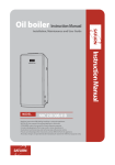
Download This user manual describes all proceedings concerning the
Transcript
This user manual describes all proceedings concerning the operations of this Drive Unit in detail as much as possible. However, it is impractical to give particular descriptions for all unnecessary or unallowable system operations due to the manual text limit, product specific applications and other causes. Therefore, the proceedings not indicated herein should be considered impractical or unallowable. This user manual is the property of GSK CNC Equipment Co., Ltd. All rights are reserved. It is against the law for any organization or individual to publish or reprint this manual without the express written permission of GSK and the latter reserves the right to ascertain their legal liability. GH Series Bus AC Servo Drive Unit User Manual PREFACE Your Excellency, It’s our pleasure for your patronage and purchase of this GH2000/GH3000 Series Bus High-speed & High-accuracy Full Digit AC Servo Drive Unit made by GSK CNC Equipment Co., Ltd. This manual is entirely described the installation, wiring, operation and debugging etc. of the GH2000/GH3000 Series Servo Drive Unit, which provides the desired knowledge and precautions for using this drive unit; it is better to operated machine after comprehending the safety precautions. Adequately play the function of the GH2000/GH3000 Series Servo Drive Unit, and ensure the safety. It is necessary to carefully read this manual before operating this machine, and correctly use this drive unit based upon the precautions and operation methods. All improvements, specifications and the version update herein are subject to change without further notice. We do not assume any responsibilities for the change of the product by user; therefore the warranty sheet will be void for this change. Chinese version of all technical documents in Chinese and English languages is regarded as final. II Safety Warning and Responsibility SAFTY WARNING To avoid the personal injury of the operators and others, as well the damage of the mechanical equipments, pay more attention to the following warning flags when reading this User Manual: That the flags shown in the following items are the danger levels during the operation, which is related with the description of the operation safety flag. And therefore, the contents are extremely important, and the user should abide by it. ! ! Danger The severe injury or death may occur if the approved instruction does not perform. Caution Notice The secondary or light wound, as well the loss of the material may occur if the approved instruction does not perform. Unexpected results and states may occur if this Notice is ignored. It reminds user that the vital requirements and important instructions are shown III GH Series Bus AC Servo Drive Unit User Manual The following marks are indicated that the operations should be performed or can not be performed: means forbidden (it cannot be performed) ! IV means enforced (it must be performed) Safety Warning and Responsibility ! Confirm whether the input power is power off before wiring. ! The electric shock may occur if the approved instruction is not observed It is better to wire or detect by the professional electrical engineer ! The electric shock or fire may occur if the approved instruction is not observed The grounding terminal PE of the servo unit should be earthed. ! The electric shock may occur if the approved instruction is not observed Do not operate the switch with wet hands! The electric shock may occur if the approved instruction is not observed. Do not open the cover of the terminal block when the power is turned on or operated! The electric shock may occur if the approved instruction is not observed. Danger Install the breaker, interference filter and AC reactor ! The thundernstrike, malfunction or damage may occur if the approved instruction is not observed. The movement, wiring, detection or maintenance can be performed after the power is turned off for 10 minutes. ! The electric shock may occur if the approved instruction is not observed. Install the ESP switch ! The personal injury, malfunction and machine damage may occur if the approved instruction is not observed. Do not stretch your hands into the servo unit! The electric shock may occur if the approved instruction is not observed. Do not touch the main circuit wiring terminal directly! The electric shock may occur if the approved instruction is not observed. V GH Series Bus AC Servo Drive Unit ! It is necessary to connect the wiring between the drive unit and motor based upon the wiring scheme ! The equipment may be damaged if the approved instruction is not observed. The load can be performed only when the dry run of the motor is executed. ! The equipment may be damaged if the approved instruction is not observed. It is essential to connect the brake resistance based upon the wiring scheme. ! The equipment may be damaged if the approved instruction is not observed. Never attempt to modify, disassemble or repair the drive unit privately. The equipment may be damaged if the approved instruction is not observed. Do not touch the motor and brake resistance, as well the radiating equipment, due to the high temperature may occur. The scald may be caused if the approved instruction is not observed. VI User Manual Caution The voltage level loaded on each terminal only can be used the one described in this manual. ! The equipment may be damaged if the approved instruction is not observed. Firstly remove the alarm, and then perform the machine when the alarm occurs. ! The equipment may be damaged if the approved instruction is not observed. The motor should be adapted with the appropriate servo motor. ! The equipment may be damaged if the approved instruction is not observed. Do not hold the cable and motor shaft during the transportation of the motor. The equipment may be damaged if the approved instruction is not observed. Do not adjust and modify the parameter extremely. The equipment may be damaged if the approved instruction is not observed. Safety Warning and Responsibility ! Do not connect the power input cables R, S and T on the U, V and W terminals of the motor output cable! The equipment may be damaged if the approved instruction is not observed. Do not repeatedly used the wasted internal electric components of the drive unit, and it only can be treated as the industry trash! The unexpected behave may occur if the approved instruction is not observed. Caution If the components of the spindle unit is absent or being damaged, it is important to touch the seller immediately before operating. The equipment may be damaged if the approved instruction is not observed. Do not frequently switch on/off the input power! The equipment may be damaged if the approved instruction is not observed. VII GH Series Bus AC Servo Drive Unit User Manual Safety Precaution ■ Transportation and storage The pile of the packing cantons should be less than 6 layers. Do not climb, stand, as well as put the heavy materials on the product. Do not use the conjoined cable with this product to drag or move the machine. Do not crash or scratch the panel and the screen. Avoid damp, sunshine and rain for the product packing ■ Unpacking detection Confirm whether the product is your purchased one after opening the packing. Check whether the product is being damaged during the transportation. Check whether each accessory is prepared or being damaged comparing the packing list. Touch our company immediately if the product type is not matched with the packing list or the components are absent or being damaged during transportation. ■ Wiring The wiring and detection should be performed by the corresponding professional. The product should be grounded stably, and its grounding resistance should be less than 0.1Ω. Do not replace the grounding wire by the neutral cable (zero). The wiring should be correct and firm, so that the product malfunction or unexpected result may occur The surge absorb diode of the product should be connected based upon the specified direction; otherwise, the product may be damaged. The power should be turned off before plug-in/out or opening the case of the product. ■ Maintenance VIII It is necessary to cut off the power before maintaining or changing the components. Safety Warning and Responsibility Check the malfunction when the short-circuit or overload occurs; the machine can be restart again after the malfunction removes. Do not frequently power on/off. The power should be turned on again after 1min. at least. Security Responsibility Security responsibility of the manufacturer ——Manufacturer should take responsibility for the design and structure danger of the motor and the accessories which have been eliminated and/or controlled. ——Manufacturer should take responsibility for the security of the motor and accessories. ——Manufacturer should take responsibility for the offered information and suggestions for the user. Security responsibility of the users ——User should know and understand about the contents of security operations by learning and training the security operations of the motor. ——User should take responsibility for the security and danger because of increasing, changing or modifying the original motor or accessory by themselves. ——User should take responsibility for the danger without following the operations, maintenances, installations and storages described in the manual. This manual is reserved by final user. We are full of heartfelt gratitude to you for supporting us in the use of GSK’s products. IX GH Series Bus AC Servo Drive Unit User Manual CONTENT 1 BRIEF························································································································ 1 1.1 Product Brief································································································································· 1 1.1.1 Product Character ················································································································· 1 1.1.2 Use Area ································································································································ 1 1.1.3 Product Appearance ·············································································································· 2 1.2 Product Technical Specification···································································································· 2 1.2.1 Technical Specification of the Drive Unit ··············································································· 2 1.2.2 The Technical Specification of the Servo Motor ···································································· 4 2 INSTALLATION ········································································································11 2.1 Ambinet Condition ·······················································································································11 2.2 The Installation of the Drive Unit ································································································ 12 2.2.1 Installation Ambient·············································································································· 12 2.2.2 Installation Dimension ········································································································· 12 2.3 Servo Motor Installation ················································································································ 15 2.3.1 Installation Ambient·············································································································· 15 2.3.2 Installation Dimension ········································································································· 16 3 WIRING··················································································································· 21 3.1 Peripheral Equipment Connection······························································································ 22 3.1.1 The Explanation of the Wiring port ······················································································ 22 3.1.2 Peripheral Equipment Connection Diagram ········································································ 22 3.2 Bus Connection ·························································································································· 24 3.3 Motor Interface Connection ········································································································ 27 3.3.1 Motor Power and Brake Wiring···························································································· 27 3.3.2 Encoder Wiring ···················································································································· 28 3.4 Battery Connection····················································································································· 29 4 DEBUGGEING ········································································································ 31 4.1 Parameter Explanation··············································································································· 31 4.1.1 Parameter List ····················································································································· 31 4.1.2 Parameter Significant Details ······························································································ 34 4.1.3 The Code Explanation of the Servo Motor Type ································································· 38 4.2 Display Operation ······················································································································· 39 4.2.1 Key Explanation··················································································································· 39 4.2.2 Main Menu Explanation ······································································································· 40 4.2.3 Monitoring Menu Explanation ······························································································ 40 4.2.4 User Shortcut Password······································································································ 42 X Content 4.2.5 Parameter Management ······································································································ 43 4.3 Function Debugging ··················································································································· 45 4.3.1 Sr Dry Run··························································································································· 45 4.3.2 JOG Operation ···················································································································· 46 4.3.3 Motor Type Write-in ············································································································· 46 4.3.4 Motor Zeroing ······················································································································ 47 5 ALARM AND TROUBLESHOOTING ·······································································49 5.1 Alarm List ··································································································································· 49 5.2 Alarm Troubleshooting ··············································································································· 50 6 ORDERING INSTRUCTION ····················································································55 6.1 The Selection of the Drive Unit ·································································································· 55 6.1.1 The Type Explanation of the Drive Unit··············································································· 55 6.1.2 The Comparison Table of the Drive Unit Adapted Motor····················································· 55 6.2 The Selected Servo Motor ········································································································· 56 6.2.1 The Type Explanation of the Servo Motor ··········································································· 56 6.3 The Selection of the Cable and Connector ················································································ 57 6.3.1 The Specification and Type of the Cable and Connector ···················································· 57 6.4 The Selection of the Peripheral Equipment ··············································································· 57 6.4.1 Brake Resistance (Necessary equipment) ·········································································· 57 6.4.2 Breaker and Contactor (Necessary equipment)·································································· 58 6.4.3 Three-phase AC Filter (Recommended equipment) ··························································· 59 6.4.4 Insulation Transformer (Necessary equipment) ·································································· 60 6.4.5 AC Reactor (Recommended Equipment)············································································ 63 XI Chapter One 1 1.1 Brief BRIEF Product Brief The GH2000/GH3000 Series Bus AC Servo Drive Unit (It is the one high-accuracy and high-speed full digit AC servo drive unit) is the updated developed one based upon the GSK-Link Ethernet Bus Agreement of our company, which provides a reliable drive control of the AC servo motor with the absolute encoder. 1.1.1 Product Character It uses the GSK-Link Ethernet bus communication method; and its data transmission rate can be performed up to about 100Mbits/s; the on-line data real-time uploading/downloading can be carried out. It uses the servo motor installed with the absolute encoder, and its encoder number can be set from17 to 28. One interface supports variable encoder agreed communications, for example, TAMAGAWA, HEIDEHAIN, DANAHER, and NIKON. Intelligently identify the motor’s type; the SJT (A4) series servo motor type or the default parameter call can be identified after the power is turned on. There are two kinds power mode selection, one is that the GH3000 series uses AC380V; the other is that the GH2000 uses AC220V. Multiple power selection, the power module 30A/50A/75A/100A/150A can be selected. 1.1.2 Use Area It can be used in these areas, such as the mechanical manufacture, CNC machine, printing & packing machine, spinning machine, robot and the automatic assembly line. 1 GH Series Bus AC Servo Drive Unit User Manual 1.1.3 Product Appearance Parameter series No. or value adds, or the menu pages up Parameter series No. or value reduces, or the menu pages down. Circularly move the modified data bit LED monitoring window The state monitoring and the modification and administration of the parameter can be performed. Indicator Return to the previous operation menu or cancel it Enter the next operation menu or confirm it. Indicator ‘CHARGE’is the high-pressure indicator of the servo unit main circuit DC bus. ON: The DC bus is with the high pressure voltage. OFF: The DC bus is already discharged. When the‘CHARGE’ Indicator is ON, the assemble or disassemble of the servo unit or the power cable, motor and the brake resistance cable can not be performed. ‘POWER’is the power indicator of the servo unit control circuit. ON: Normal. OFF: Power-down ‘CN1’ is the servo unit encoder feedback input (high density DB26 socket) ‘BUS1/BUS2’is the communication bus interface of the Ethernet. The grounding terminals of the input power and the motor protection one ‘Hold’ is the brake output terminal Fig. 1-1 Product appearance 1.2 Product Technical Specification 1.2.1 Technical Specification of the Drive Unit Table 1-1 The main technical specification parameter of the drive unit Drive unit type GH2030 GH2050 GH2075 GH2100 GH3048 GH3050 GH3075 GH3100 IPM module power (A) 30 50 75 100 50 50 75 100 Adapted servo motor rated current (A) 4<I≤6 7<I≤10 10<I≤15 15< I≤29 4<I≤6 7<I≤10 10< I≤15 15< I≤29 Main circuit power Three-phase, AC 220V Three-phase, AC 380V Control circuit power Single-phase, AC 220V Single-phase, AC 380V Brake resistance Control method 2 Built-in External needed (without built-in) Built-in External needed (without built-in) Three-phase full-wave rectification IGBT PWN sine wave drive Chapter One Brief Feedback method 17-bit absolute encoder (It is compatible with TAMAGAWA, HEIDEHAIN, DANAHER, and NIKON) Communicat ion method GSK-LINK bus communication method: the Max. connection number: 254 axes; the data transmission ratio: 100Mbits/s Speed frequency ≥200Hz response Speed-regul ation ratio 1: 60000 The least speed control ±0.1r/min PID response Velocity loop: 10KHz Current loop: 10KHz frequency Working method Manual, JOG, external velocity (Bus agreement) Working ambient Working temperature: 0℃~+40℃ Storage temperature: -40℃~+70℃ temperature Working ambient Less than 90% (No condensation) humidity Vibration-res istance/impa Less than 0.5G (4.9m/s2)(Discontinuous operation in the 10Hz~60Hz) ct-resistance Protective function Monitoring function Display operation Overspeed, overpressure, main circuit open-phase, power module failure, underpressure, overload, overheat, brake abnormal, encoder abnormal, encoder communication failure, motor type setting enabled, control power abnormal etc. Motor speed, encoder feedback single-circle value/multiple-circle value, motor current, operation state, CUP use rate, Ethernet state, speed command value, alarm prompt. 6-digit LED Nixie tube, 5 keys. 3 GH Series Bus AC Servo Drive Unit 1.2.2 User Manual The Technical Specification of the Servo Motor Table 1-2 The technical parameter of 80 series motor Type Item Rated power (kW) 80SJT-M024C 80SJT-M024E 80SJT-M032C 80SJT-M032E 0.5 0.75 0.66 1.0 Polar logarithm Rated current (A) Zero speed torque (N.m) Rated torque (N.m) The Max. torque (N.m) Rated speed (r/min) The Max. speed (r/min) Inertia of moment 4 3 4.8 5 6.2 2.4 2.4 3.2 3.2 2.4 2.4 3.2 3.2 7.2 7.2 9.6 9.6 2000 3000 2000 3000 2500 4000 2500 4000 0.83×10⁻⁴ 1.23×10⁻⁴ 1.23×10⁻⁴ 2.9 3.4 3.5 0.83×10⁻⁴ (kg·m2) Weight (kg) Insulation level F(GB 755—2008) Vibration level R(GB 10068—2008) Defense level IP65(GB 4208—2008/IEC 60529:2001,GB/T 4942.1—2006) Installation type IMB5(Flange installation)(GB/T 997—2008 / IEC 60034-7:2001) Working system S1(Consecutive working system)(GB 755—2008) Power-down brake Adapted encoder 4 2.8 Not available Increment 2500p/r, 5000p/r etc., absolute encoder 17 bit single circle or multiple circles Chapter One Brief The torque-speed character figure (T – M) of the servo motor is shown below: A: Continuous working area B: Short time working area Speed (r/min) Speed (r/min) Torque (N.m) Torque (N.m) Speed (r/min) Speed (r/min) Torque (N.m) Torque (N.m) Table 1-3 The technical parameter of 110 series motor Type 110SJT-M 040D 110SJT-M 040E 110SJT-M 060D 110SJT-M 060E 130SJT-M 040D 130SJT-M 050D Item Rated power 1.3 1.0 1.2 1.5 1.8 1.0 (kW) Polar 4 logarithm Rated 5 4.5 5 7 8 4 current (A) Zero speed 5 4 4 6 6 torque (N.m) Rated torque 5 4 4 6 6 4 (N.m) The Max. 12.5 12 10 12 12 10 torque (N.m) Rated speed 2500 3000 2500 3000 2500 2500 The Max. 3000 3300 3000 3300 3000 3000 speed Inertia of 0.68×10⁻³ 0.68×10⁻³ 0.95×10⁻³ 0.95×10⁻³ 1.1×10⁻³ 1.1×10⁻³ moment Weight (kg) 6.1 6.1 7.9 7.9 6.5 6.5 The motor weight with 7.7 7.7 9.5 9.5 8.1 8.1 the power-down brake (kg) Insulation B(GB 755-2008) level Vibration R(GB 10068-2008) level IP65(GB/T4942.1-2006) Defense 5 GH Series Bus AC Servo Drive Unit User Manual level Installation type Working system Adapted encoder IMB5(Flange installation)(GB/T 997-2008 / IEC 60034-7:2001) S1(Consecutive working system)(GB 755-2008) Increment 2500p/r, 5000p/r etc., absolute encoder 17 bit single circle or multiple circles The torque-speed character figure (T – M) of the servo motor is shown below: A: Continuous working area Speed (r/min) B: Short time working area Speed (r/min) Speed (r/min) Torque (N.m) Torque (N.m) Torque (N.m) Speed (r/min) Speed (r/min) Speed (r/min) Torque (N.m) Torque (N.m) Torque (N.m) Table 1-4 The main technical parameter of the 130SJT series motor (to be continued table 1-3) Type 130SJT-M 060D 130SJT-M 075D 130SJT-M 100B 130SJT-M 100D 130SJT-M 150B 130SJT-M 150D Item Rated power 3.9 1.5 1.88 1.5 2.5 2.3 (kW) Polar 4 logarithm Rated 6 7.5 6 10 8.5 14.5 current (A) Zero speed 6 7.5 10 10 15 15 (N.m) Rated torque 6 7.5 10 10 15 15 (N.m) The Max. 18 20 25 25 30 30 torque (N.m) Rated speed 2500 2500 1500 2500 1500 2500 The Max. 6 3000 3000 2000 3000 2000 3000 Chapter One Brief speed Inertia of moment Weight (kg) The motor weight with the power-down brake (kg) Insulation level Vibration level Defense level Installation type Working system Adapted encoder 1.33×10⁻³ 1.85×10⁻³ 2.42×10⁻³ 2.42×10⁻³ 3.1×10⁻³ 3.6×10⁻³ 7.2 8.1 9.6 9.7 11.9 12.7 10.1 11 12.5 12.6 14.8 15.6 B(GB 755-2008) R(GB 10068-2008) IP65(GB/T4942.1-2006) IMB5(Flange installation)(GB/T 997-2008 / IEC 60034-7:2001) S1(Consecutive working system)(GB 755-2008) Increment 2500p/r, 5000p/r etc., absolute encoder 17bit single circle or multiple circles The torque-speed character figure (T – M) of the servo motor is shown below: A: Continuous working area Speed (r/min) B: Short time working area Speed (r/min) Speed (r/min) Torque (N.m) Torque (N.m) Speed (r/min) Speed (r/min) Speed (r/min) Torque (N.m) Torque (N.m) Torque (N.m) Torque (N.m) 7 GH Series Bus AC Servo Drive Unit User Manual Table 1-5 The main technical parameter of the 175SJT series motor Type Item Rated power (kW) 175SJT-M120E 175SJT-M150B 175SJT-M150D 175SJT-M180B 175SJT-M180D 3 2.4 3.1 2.8 3.8 Polar 3 logarithm Rated current (A) Zero torque (N.m) Rated torque (N.m) The Max. torque (N.m) Rated speed 13 11 14 15 16.5 12 15 15 18 18 9.6 15 12 18 14.5 19.2 30 24 36 29 3000 1500 2500 1500 2500 2000 3000 2000 3000 5.1×10⁻³ 5.1×10⁻³ 5.1×10⁻³ 6.5×10⁻³ 6.5×10⁻³ 18.9 18.5 19 22.8 22.9 24.5 24.1 24.6 28.4 28.5 The Max. speed Inertia of moment Weight (kg) 3300 The motor weight with power-down brake (kg) Insulation level Vibration level Defense level Installation type Working system 8 B(GB 755-2008) R(GB 10068-2008) IP65(GB/T4942.1-2006) IMB5(Flange installation)(GB/T 997-2008 / IEC 60034-7:2001) S1(Consecutive working system)(GB 755-2008) Adapted Increment 2500 p/r, 5000 p/r etc., absolute encoder 17 bit single circle or multiple encoder circles Chapter One Brief The torque-speed character figure (T – M) of the servo motor is shown below: A: Continuous working area Speed (r/min) B: Short time working area Speed (r/min) Speed (r/min) Torque (N.m) Torque (N.m) Torque (N.m) Speed (r/min) Speed (r/min) Torque (N.m) Torque (N.m) Table 1-6 The main technical parameter of the 175SJT series motor (to be continued the table 1-5) Type Item Rated power (kW) Polar logarithm Rated current (A) Zero speed torque (N.m) Rated torque (N.m) The Max. torque (N.m) 175SJT-M220B 3.5 175SJT-M220D 175SJT-M300B 175SJT-M300D 175SJT-M380B 4.5 3.8 6 6 3 17.5 22 22 44 Rated speed 1500 The Max. speed Inertia of moment Weight (kg) The motor weight with power-down brake (kg) Insulation level 2000 9.0×10⁻³ 19 19 27.5 29 22 30 30 38 17.6 24 24 38 35.2 48 48 76 2500 1500 2500 1500 3000 2000 3000 1800 11.2×10⁻³ 11.2×10⁻³ 9.0×10⁻³ 14.8×10⁻³ 28.9 29.2 34.3 34.4 42.4 34.5 36.8 42 42.1 50.1 B(GB 755-2008) 9 GH Series Bus AC Servo Drive Unit Vibration level R(GB 10068-2008) Defense level IP65(GB/T4942.1-2006) Installation type Working system Adapted encoder User Manual IMB5(Flange installation)(GB/T 997-2008 / IEC 60034-7:2001) S1(Consecutive working system)(GB 755-2008) Increment 2500p/r, 5000p/r etc., absolute encoder 17 bit single circle or multiple circles The torque-speed character figure (T – M) of the servo motor is shown below: A: Continuous working area Speed (r/min) B: Short time working area Torque (N.m) Torque (N.m) Torque (N.m) Speed (r/min) Speed (r/min) Torque (N.m) 10 Speed (r/min) Speed (r/min) Torque (N.m) Chapter Two 2 Notice Installation INSTALLATION The storage and installation of the product should be suitable for the ambient conditions. The pile number of the product should be controlled, which can not be piled them together too many, so that the product may be crushed or dropped. The storage and transportation of the product should be used the original packing. Do not use the product with damaged or absent components. Do not install it on the flammable surface or near, to avoid the fire hazard. The servo drive unit should be installed inside the electric cabinet; prevent the dust, corrosive gas, conductive material, liquid and the inflammable matter from entering the machine. The servo drive unit and servo motor can not be shocked and impacted. 2.1 Ambinet Condition Item GH2000/GH3000 series servo drive unit SJT series AC servo motor Using 0℃~+40℃(No freeze) 0℃~+40℃ (No freeze) temperature/ Below 90%RH (No condensation) Below 90%RH(No condensation) humidity Storage -40℃ ~ +70℃, 90%RH (No temperature/ condensation) Below -40℃ ~ +70℃, 90%RH (No condensation) humidity Atmosphere ambient Altitude Vibration Defense level There is no corrosive gas, inflammable There gas, oil mist or dust inside the control inflammable gas, oil mist or dust in the cabinet. house (without sunshine). Blow 1000m is no corrosive gas, Below 1000m 2 Less than 0.5G (4.9m/s ) 10Hz~60Hz (Nonconsecutive) IP43 IP65 11 GH Series Bus AC Servo Drive Unit User Manual 2.2 The Installation of the Drive Unit 2.2.1 Installation Ambient Defense The servo drive unit should be installed well-mounted electric cabinet, because its structure is without defense. Prevent the corrosive gas, inflammable gas, as well as the conductive material, metal dust, oil mist and liquid from entering the machine. Temperature, humidity The ambient temperature is 0℃~+40℃, and ensure the radiating condition. Vibration and impact The installation of the drive unit can not be shocked, and the vibration control should be less than 0.5G (4.9m/s2) based upon the buffering measure. The installation of the drive unit must be far away from the heavy load and impact. 2.2.2 Installation Dimension The GH2000/GH3000 series drive unit adopts base plate installation method, of which its installation direction is vertical to the installation surface and upward. The front is forward and the top surface is upward for cooling when the drive unit is installed. Note that the necessary space around the machine should be reserved. In order to guarantee the ambient temperature of the drive unit does not rise consecutively, the convection air should blow to the radiator of the drive unit inside the electric cabinet. Fig. 2-1 GH2030T installation dimension (Unit: mm) 12 Chapter Two CHARGE Installation POWER Warning Fig. 2-2 GH2050T, GH3048T installation dimension (Unit: mm) CHARGE POWER Fig. 2-3 GH2075T, GH3050T installation dimension (Unit: mm) 13 GH Series Bus AC Servo Drive Unit Fig. 2-4 GH2100T, GH3075T installation dimension (Unit: mm) Fig. 2-5 GH3100 installation dimension (Unit: mm) 14 User Manual Chapter Two Installation 2.3 Servo Motor Installation Notice Do not knock the motor shaft or encoder, and prevent the motor from the shocking or impacting. Do not drag the motor shaft, leading wire or encoder cable when transporting the motor. The motor may be damaged if the motor shaft is overload. The motor installation should be firm and the locking measure should be ready. 2.3.1 Installation Ambient (1) Defense At present, GSK SJT series servo motors are not waterproof, and therefore, prevent the liquid from splashing to the motor during installing or using, and guard against the oil or water enter the motor from the motor leading wire and the shaft. Note: It is necessary to state in the order if you need the waterproof servo motor. (2) Temperature, Humidity The ambient temperature should be ranged 0~+40℃. The motor may heat up if it is operated for long time. It is considered that the motor should be cooled by force if the space around the machine is narrow or the heating equipment is accompanied with it. The humidity should be less than 90%RH, and no condensation occurs. (3) Vibration It is avoid to install the servo motor in the vibration situation, and its oscillation should be less than 0.5G(4.9m/s2). 15 GH Series Bus AC Servo Drive Unit 2.3.2 User Manual Installation Dimension (1) 80SJT series seat number AC servo motor appearance and installation dimension Industry (aviation) socket Direct cable 16 Type D(mm) N(mm) LB(mm) L(mm) 80SJT—M024C(A4) φ190-0.013 φ700-0.03 163 198 80SJT—M024E(A4) φ190-0.013 φ700-0.03 163 198 80SJT—M032C(A4) φ190-0.013 φ700-0.03 181 216 80SJT—M032E(A4) φ190-0.013 φ700-0.03 181 216 Chapter Two Installation (2) 110 SJT series AC servo motor appearance and installation dimension Type D(mm) N(mm) LB(mm) L(mm) 110SJT—M040D(A4) φ190-0.013 φ950-0.035 186 (237) 241 (292) 110SJT—M040E(A4) φ190-0.013 φ950-0.035 186 (237) 241 (292) 110SJT—M060D(A4) φ190-0.013 φ950-0.035 212 (263) 267 (318) 110SJT—M060E(A4) φ190-0.013 φ950-0.035 212 (263) 267 (318) Note: LB and L inside the bracket are the length value of corresponding specification with the power-down brake motor. (3) 130SJT series AC servo motor appearance and installation dimension 17 GH Series Bus AC Servo Drive Unit User Manual Type D(mm) N(mm) LB(mm) L(mm) 130SJT—M040D(A4) φ220-0.013 φ1100-0.035 168 (227) 225 (284) 130SJT—M050D(A4) φ220-0.013 φ1100-0.035 168 (227) 225 (284) 130SJT—M060D(A4) φ220-0.013 φ1100-0.035 176 (235) 233 (292) 130SJT—M075D(A4) φ220-0.013 φ1100-0.035 188 (247) 245 (304) 130SJT—M100B(A4) φ220-0.013 φ1100-0.035 208 (267) 265 (324) 130SJT—M100D(A4) φ220-0.013 φ1100-0.035 208 (267) 265 (324) 130SJT—M150B(A4) φ220-0.013 φ1100-0.035 238 (297) 295 (354) 130SJT—M150D(A4) φ220-0.013 φ1100-0.035 248 (307) 305 (364) Note: LB and L inside the bracket are the length value of corresponding specification with the power-down brake motor. (4) 175 SJT series AC servo motor appearance and installation dimension Type D(mm) N(mm) LB(mm) L(mm) 175SJT—M150D(A4) φ350+0.01 φ114.30-0.025 224 (291) 303 (370) 175SJT—M180B(A4) φ350+0.01 φ114.30-0.025 244 (311) 323 (390) 175SJT—M180D(A4) φ350+0.01 φ114.30-0.025 244 (311) 323 (390) 175SJT—M220B(A4) φ350+0.01 φ114.30-0.025 279 (346) 358 (425) 175SJT—M220D(A4) φ350+0.01 φ114.30-0.025 279 (346) 358 (425) 175SJT—M300B(A4) φ350+0.01 φ114.30-0.025 309 (382) 388 (461) 175SJT—M300D(A4) φ350+0.01 φ114.30-0.025 309 (382) 388 (461) Note: LB and L inside the bracket are the length value of corresponding specification with the power-down brake motor. 18 Chapter Two Installation Precautions: To avoid the damage in the encoder, do not knock the motor or its shaft when disassembling the belt wheel. It is better use the spiral press/pull tool to dismount it. At present, most SJT series motors can not be undergone the large shaft and diameter direction load. It is recommended to connect the load by the flexible coupler. Use the locking cushion to fix motor against the motor releases. 19 GH Series Bus AC Servo Drive Unit 20 User Manual Chapter Three Wiring 3 WIRING Notice It is essential to carefully read this chapter for ensuring your personal safety. The wiring should be operated by the professional and correctly connected based upon the related explanations. In order to guarantee the equipment can be correctly operated under the terrible surroundings, it is better to wiring according to the related electromagnetism regulations. The wiring or inspection should be performed after affirming the grounding voltage of each main circuit terminal is safe by the Multimeter, after the drive unit is turn off for 5min, otherwise, the electric shock may occur. Confirm the drive unit and servo motor is correctly grounded. To avoid the cable is being damaged by the sharp object, do not drag the cable by force during wiring, otherwise, the electric shock or the fault connection may occur. Do not traverse the main circuit and the signal cables with the same pipeline and tie them up together. During wiring, the main circuit cable should be separated from the signal one, up to 30cm above. In this case, guard against the strong circuit is interrupted Do not cut ON/OFF the power frequently, because there is wide capacity inside the drive unit. The bigger current may occur when the power is turned on, and the component inside the drive unit may be shortened the life span if the power is frequently ON/OFF. It is recommended to wait 30min above when the power is turned on or off. Both the main circuit wiring and signal wire can not be closed to the radiating equipment and motor, so that the insulation capacity is reduced due to the heat. The terminal protection cover should be closed for avoiding electric shock, after the main circuit connection is performed. Any equipment, such as the power capacity, surge absorber and the wireless noise filter etc., can not add between the drive unit output side and servo motor. Servo motor U Servo unit V PMSM 3~ W PE 21 GH Series Bus AC Servo Drive Unit User Manual 3.1 Peripheral Equipment Connection 3.1.1 The Explanation of the Wiring port Table 3-1 The definition of the drive unit wiring port Terminal mark R, t U, V, W PE The contravariant power input of the drive unit main circuit The switch power input of the drive unit control board Connect with the three-phase winding U, V and W of the motor Connect with the power grounding and motor grounding The brake resistance is available for the dynamic brake; the drive unit without built-in brake resistance only can be normally operated by connecting with the external brake resistance. Brake resistance terminal P, B1, B BUS1/BUS 2 HOLD Explanation AC power input terminal AC power input terminal Three-phase AC output terminal Protective grounding terminal R, S, T CN1 Name Bus communication terminal Encoder wiring terminal Brake wiring terminal It is connected with system or drive unit in series. Refer to the Bus connection explanation in Fig. 3-3 High density 26pin DB pin, and it is connected with the motor encoder. The motor hold relay control interface and the optical coupler insulation circuit included. Table 3-2 The suggestion table of the used cable and cord terminal of the drive unit R, S, T/U, V, W r, t P, B1, B PE Terminal screw dimension φmm Cable diameter mm2 Terminal screw dimension φmm Cable diameter mm2 Terminal screw dimension φmm Cable diameter mm2 Terminal screw dimension φmm Cable diameter mm2 GH2030 Rated current of the adapted motor I(A) 4.5<I≤6 3.5 1.5 3.5 1 3.5 1.5 3.5 1.5 GH2050 6<I≤10 3.5 2.5 3.5 1 3.5 2.5 4 2.5 GH2075 10<I≤15 4 4 4 1 4 2.5 5 2.5 GH2100 15<I≤29 6 4 4 1 6 4 5 4 3.1.2 Peripheral Equipment Connection Diagram Product type The following items in the peripheral equipment connection diagram should be observed: The breaker, AC filter and the AC contactor should be configured by the user, and the other equipments can be purchased from GSK. Refer to the Chapter Six for the selection of the breaker, AC filter, insulation transformer, AC reactor and the AC contactor. The peripheral equipment marked with “must be assembled” can be ensured that the user can use the servo equipment safely and stably, as well reduce the loss as much as possible when the user equipment malfunction occurs. 22 Chapter Three Wiring The peripheral equipment marked with the “optional” can be guaranteed the stable operation in the drive unit when the power is on the bad surroundings. L1 L2 L3 3N ~ 50/60Hz 380V Breaker (Required) GSK 25i AC380V Transformer (Required) AC220V Filter (Optional) P2 P1 Reactor (Optional) AC Contactor (Required) CHARGE POWER ~ S R 220V BRAKE T P B1 B U V W r t Red Blue 220V ~ Brown MOTOR Control circuit (Refer to the Fig. 3-2 for details) Brake resistance (Optional) Use the built-in brake resistance, B1, B short-circuit; Use the external brake resistance, Connect the P and B based upon the figure; Notice: Some of the servo units are without built-in Brake resistance (Refer to the Table 1-1) Brake resistance heats due to discharge, Do not touche, so as not to burn! Yellow green PE Brake circuit (Refer to the Fig. 3-2 for detials) Fig. 3-1 GH2000/GH3000 reference connection diagram of the Ethernet bus method Notice ٛ ٛ ٛ The B1 and B Terminals must be connected with Short-circuit regardless of the external brake resistance; and the B1 and B should be cut when the external brake resistance is performed. The motor cable in our factory has been marked with The U, V, W and PE wiring port, which should be connected with the U, V, W and PE port of the servo unit one by one, otherwise, the motor can not be operated normally! Correctly connect the protective grounding terminal, and its grounding resistance should be less than 10Ω. 23 GH Series Bus AC Servo Drive Unit ~ KA1 220V AC ~ ~ TB FIL KM1 KM1 R S T PE r t GH series servo unit 380V ON OFF RC MCCB User Manual Cut off the B1, B when the external brake resistance is connected. B1 and B should be connected whit short-circuit when the external brake resistance is not connected. U 4 V 3 W 2 PE 1 Servo motor MS 3~ 1 Brake Encoder feedback signal CN1 P B1 2 Grounding HOLDHOLD HOLD+ KA2 B GND KA2 0V 24V VDD Brake resistance Fig. 3-2 The control circuit of the main loop 3.2 Bus Connection The GSK-Link industry Ethernet bus is based on the IEEE 802.3(Ethernet)area, unit internet and ring topological structure, which adopts the physical-layer chip. The transmission medium uses the ultra 5-kind twisted pair line and RJ45 interface, and its transmission rate is 100Mbits/s. GH series drive unit adopts GSK-Link industry Ethernet bus communication method, which can be connected between drive units, drive unit and CNC system by the net wire; the maximum connection is up to 254 nodes. The communication period data only can be transited between the main station (CNC system) and servo slaver one; the non-period data can be performed among any stations. The GSK-Link bus employs double-ring topological structure; the bus topology is shown as Fig. 3-3. The structure of communication module both the main and slaver stations are absolute same. Notice 1. The connection sequence and drive unit IP address are corresponding; refer to the system operation manual for details. 2. The connection of the I/O module does not mark in the Fig. 3-3 connection diagram. The method of connection diagram that adds the I/O module is same to the drive unit one. 24 Chapter Three Wiring 3. Suppose that it is regarded as X/YZ in turn from left to right, the Fig. 3-3 shows the single-direction circuit schematic, that is, the CNC system P1 interface communication begins from X axis BUS1, and ends to the Z axis BUS2. In addition, another circuit communication connection can be carried out, namely, the CNC system P1 interface communication starts from X axis BUS1, and ends to the BUS2. 4. I/O module must be placed at begin or end of the circuit regardless of connection method, and it can not be connected between drive units. GSK 25i P2 P1 POWER CHARGE T P B1 B U V W r t T P B1 B U V W r t 220V ~ MOTOR Red Blue 220V ~ Brown MOTOR 220V PE BRAKE BRAKE MOTOR Red Blue Yellow green Yellow green Yellow green 220V 220V BRAKE Brown ~ ~ ~ T P B1 B U V W r t POWER S S R 220V Red Blue CHARGE S Brown POWER R ~ CHARGE R PE PE Fig. 3-3 GH series topological structure diagram between drive unit and system 25 GH Series Bus AC Servo Drive Unit Bus interface 1 Pin explanation of bus interface 1 (BUS 1) Pin No. 1 2 3 4 5 6 7 8 8 7 6 5 4 3 2 1 Bus interface 2 Pin explanation TX1+, white green TX1-,green RX1+,orange white NC,blue NC,blue white RX1-,orange NC,brown white NC,brown Pin explanation of bus interface 2 (BUS 2) Pin No. 1 2 3 4 5 6 7 8 8 7 6 5 4 3 2 1 User Manual Pin explanation TX2+,white green TX2-,green RX2+,orange white NC,blue NC,blue white RX2-,orange NC,brown white NC,brown Fig. 3-4 GH series drive unit RJ45 interface definition One port of the network cable connector Another port of the network cable connector Pin6 Pin2 Blue Orange Pin1 Yellow Pin6 Pin2 Orange Blue Pin3 White Pin1 White The connection schema of the network cable terminal Fig. 3-5 4-core net wire crystal-head connection diagram 26 Pin3 Yellow Chapter Three Wiring 3.3 Motor Interface Connection Motor power socket Power-down brake socket Encoder signal socket Fig. 3-6 The explanation of motor interface 3.3.1 Motor Power and Brake Wiring The definition of the motor power socket: 4 1:PE 3 2 2:Phase U 1 3:Phase V 4:Phase W The socket of motor power The definition of powerdown brake socket: 1, 2:DC24V 3 1 2 3:Unsettled The socket of the power-down brake Fig. 3-7 The definition of the motor and brake interface Note: ① 1/2 pin connects 24V, regardless of the positive/negative ② The selection of the 24V power refers to the table 3-3. Table 3-3 The selection of the brake power supply Motor Rated 20℃ brake coil Release type torque power (Unit: W) time (s) 110 4 20 130 8 175 32 Voltage Power 0.037 24V DC ≥30W 25 0.042 24V DC ≥40W 40 0.135 24V DC ≥50W 27 GH Series Bus AC Servo Drive Unit 3.3.2 User Manual Encoder Wiring 26 25 24 PEA-(Testing) 22 PEA+(Testing) 20 CLK- 18 +5V 16 0V 14 FG 23 SD+ PEB-(Testing) 21 15 SD- 11 PEB+(Testing) 9 +3.6V 7 19 17 13 +5V FG 5 +5V 3 0V 1 0V 12 PEZ+(Testing) 10 PEZ-(Testing) 8 CLK+ 6 +5V 4 0V 2 0V Fig. 3-8 The pin definition of the 26-pin high density socket of the drive unit Encoder interface (15-female aviation socket) 1 FG 3 0V 2 SD6 SD+ 5 +5V 13 +3.6V 8 CLK+ 11 CLK- GH2000/GH3000 CN1 (High-density 26-male socket) Wiremesh external FG shell iron plate 1,2,3,4,16 0V 13 SD25 SD+ 5,6,17,18 +5V 9 +3.6V 8 CLK+ 20 CLK- Fig. 3-9 The wiring diagram (A4 motor) of GH2000/GH3000 drive unit encoder interface CN2 (26-pin) Notice: +5V uses 4 pieces wires, 0V uses 5 pieces wires and 3.6V uses 2, which are together connected to the aviation socket in series to prevent the voltage reduction from transiting with long distance. SD+/SD- must be used a pair of twisted pair wire to improve the signal transmission quality. CLK+/CLC- is treated as HEIDEHAIN encoder clock signal, which should be used a pair of twisted wire. The clock signal may unsettle if it is not the HEIDEHAIN encoder. 28 Chapter Three Wiring 3.4 Battery Connection If the servo motor is installed the TAMAGAWA absolute encoder, the battery should be installed in the servo drive unit battery flat to memory the multi-circle value. The battery need not install if the servo motor is mounted the HEIDEHAIN or DANAHER absolute encoder. GH series drive unit is adapted with VARTA 3.6V/1200mAh made in Germany before delivery, which can not charge with the Lithium battery, its life span is 3 years and consecutive reserve time is 12000h. The battery is connected with the drive unit by a 2-pin socket, the red wire is positive, and the black is negative. This is the positive where the battery contact pin is closed to the button, and the other is negative. Absolute encoder battery installation position, up “-” down “+” Notice: Ensure the battery polarity is correct, otherwise, the encoder may be damaged in short-circuit. Normally, the battery consecutive reserve is 12000h, but if the huge leak current may have, the life span then may be shortened. The new battery should be changed when the drive unit prompts the battery alarm (Refer to 4.2.3 explanation). 29 GH Series Bus AC Servo Drive Unit 30 User Manual Chapter Four Debugging 4 Notice DEBUGGEING The person who attends to the debugging should understand the parameter significant; incorrect setting may cause the equipment damage and personal injury. It is recommended that the dry run of the servo motor should be performed after the debugging of the parameter. The motor parameter adapts the GSK SJT series servo motor with the absolute encoder, if other motors are used, the corresponding parameter then should be debugged, otherwise, the motor operation may abnormal. 4.1 Parameter Explanation 4.1.1 Parameter List The factory value of the drive unit in the following list adapts the GSK 130SJT-M075D (A4) (7.5N.m, 2500r/min) motor, which is treated as an example, refer to the following list. The relative parameters differ depending on the motors. It is better to adjust based upon the parameter debugging guide or the technical person. Table 4-1 GH drive unit parameter list (software version V4.42) Paramet er No. 0 1 2 3 4 5 6 7 8 9 10 11 12 13 14 15 16 Parameter significant Default Numerical range Password Motor type code Version number Initial display state Control method selection Velocity proportional gain Velocity integral time constant (ms) Torque command filter coefficient (%) Velocity detection low-pass filter coefficient (%) Position proportional gain Position feed forward gain Position feed forward low-pass cut-off frequency (Hz) Electric gear ratio numerator Electric gear ratio denominator Position command input method Position command direction The completion range of the positioning 315 27 420 0 0 450 150 100 100 245 0 1~9999 0~100 0~32767 0~21 0~7 5~1280 1~32767 10~2000 10~2000 0~2000 0~1280 300 1~2000 8192 500 0 0 20 0~32767 0~32767 0~2 0~1 0~32767 31 GH Series Bus AC Servo Drive Unit 17 18 19 20 21 22 23 24 25 26 27 28 29 30 31 32 33 34 35 36 37 38 39 40 41 42 43 44 45 46 47 48 49 50 51 52 53 54 55 56 57 58 59 60 61 62 32 Position excess-error detection range Position excess-error fault detection enabled Velocity command low-pass filter cut-off frequency (Hz) Drive prohibition disabled JOG velocity Velocity command filter switch Top speed limit Inner speed 1 Inner speed 2 Inner speed 2 Inner speed 4 Arrival speed The 2nd velocity integral time constant Reserved Reserved Reserved The speed in the motor testing method Inner CCW torque limit Inner CW torque limit Reserved Reserved Dry run speed torque limit Main circuit open-phase detection enabling position Parameter auto-tuning enabled positioning Servo output pulse number The Max. frequency of the servo response Reserved Parameter auto-tuning current input Reserved The enabled digit of encoder multi-circle value abnormal alarm Velocity command gain Reserved Reserved Reserved Reserved Parameter auto-tuning current amplitude-limit value Parameter auto-tuning velocity low-pass filter cut-off frequency (Hz) Reserved Reserved Output time in advance, if the feedback pulse is more than 10000. Velocity command feed forward gain Acceleration feedback gain Inertia stop reduction coefficient Current proportional gain Current integral time constant Current integral separation point User Manual 1310 0 0~32767 0~1 100 15~15000 0 100 0 3000 0 100 300 -100 500 2000 10 1 3 100 300 -300 100 -100 100 0~1 -6000~6000 0~1 0~6000 -6000~6000 -6000~6000 -6000~6000 -6000~6000 0~6000 0~32767 0~32767 0~32767 0~4 0~6000 0~300 -300~0 0 0~10000 0 2500 200 1 95 100 10~1000 0~32767 50~600 0~1 0~32767 0~32767 0 0~3 1000 2767 0 120 200 20~3000 0~32767 0~1 0~32767 0~32767 40 0~100 65 10~2000 1000 1000 20~3000 20~3000 20 0~32767 0 500 2 950 150 40 0~32767 -10000~0 1~4 0~12800 1~32767 0~32767 0~300 Chapter Four Debugging 63 64 65 66 67 68 69 70 71 72 73 74 75 76 77 78 79 80 81 82 83 84 85 86 87 88 89 90 91 92 93 94 95 96 97 98 99 100 101 102 103 104 105 106 107 108 109 110 The alteration ratio of the current proportional gain The cut-off frequency of the current low-pass filter Velocity integral separation point The alteration ratio of the velocity proportional gain Velocity output amplitude-limit 1 Velocity output amplitude-limit 2 Current output amplitude-limit Reference standard voltage Motor rotor inertia Motor rated torque Motor rated speed The Max. allowable current of the sampling circuit Rated current of the motor The Max. allowable overload multiple of the motor Current PID modification coefficient along q axis Current PID modification coefficient along d axis The repeated time of the parameter auto-tuning The 2nd current integral time constant Velocity PID modification coefficient The current proportional gain of parameter auto-tuning Delay time of main circuit overpressure alarm Delay alarm time of main circuit brake Delay time of drive enabling Delay time of module alarm Delay time of main circuit undervoltage alarm Communication error counter of absolute encoder The longest completion time of encoder null Reserved Encoder control method Velocity gain shift valve value at low speed Velocity gain shift coefficient at low speed Reserved Magnetic polar logarithm Open-loop operation voltage Open-loop operation speed SON force enabling The voltage value of encoder null Feedback velocity gain Reserved Z pulse output impulse-width modulation Reserved Velocity filter cut-off frequency 0 Velocity filter cut-off frequency 1 Velocity filter cut-off frequency 2 Velocity filter cut-off frequency 3 Inert stop selection Velocity filter separation point 0 Velocity filter separation point 1 150 0~32767 1000 100 0~32767 0~32767 100 0~32767 1000 1000 950 1700 650 180 2500 5000 150 200 200 200 1000 600 500 100~2000 100~2000 100~1000 1000~3100 0~32767 0~32767 0~32767 0~32767 0~32767 0~32767 0~32767 0~32767 0~32767 1~32767 0~32767 3000 0~32767 1 1 150 50 10 2 3000 0 0 100 100 15000 3 1395 18 0 4000 1000 80 30 0 100 110 130 170 1 1 10 0~32767 0~32767 0~32767 0~32767 0~32767 0~32767 0~32767 0~1 0~20 0~3000 0~300 0~32767 0~8 0~31000 0~3000 0~1 0~31000 0~300 0~1 0~32767 0~1 0~32767 0~32767 0~32767 0~32767 0~32767 0~32767 0~32767 33 GH Series Bus AC Servo Drive Unit 111 112 113 114 115 116 117 118 119 120 4.1.2 Velocity filter separation point 2 Motor type alarm shielding Power-off brake at the rapid traverse rate Delay time of overcurrent alarm Delay time enabling detection in power-on Proportional gain coefficient in velocity integral separation Delay time of release brake Brake delay time The proportional gain coefficient of the current integral separation Automatic elimination delay time of undervoltage/overpressure alarm 35 0 0 1 1 0~32767 0~1 0~1 0~200 0~1 100 10~1000 1500 10000 0~32767 0~32767 100 10~1000 4 0~32767 Parameter Significant Details Table 4-2 Series No. PA0 Description PA1 PA4 Parameter function Parameter range Default Unit Parameter 0~9999 315 password ① Prevent the parameter from modifying by fault. Generally, when the parameter needs to be set, firstly set the parameter to the desired password, and then set the parameter. The power-on user password is 315 be default, which can be debugged the parameter from 3 to 60. ② Refer to the relative setting explanation for the other passwords. Motor type code 34 User Manual 0~100 66 ① Different type codes differ from the parameter default values, the parameter should correct when the default parameter function is recovered. ② When the absolute encoder wire-break alarm (No.19) occurs or the motor type without alarm (No.18) is modified, the default parameter then can be automatically recovered, during the power is turned on, otherwise, the drive unit may abnormal or be damaged. Firstly set the password PA0 to 385, and then modify this parameter. Control method 1~7 1 selection ① The control method of the drive unit can be set based upon this parameter: 1: Velocity control method; 2. Dry run control method; 3: JOG control method; 4: Encoder null method; 5: Motor testing method; 6: Open-loop operation method (it is used for testing the motor and encoder); 7: The write-in method of the drive unit type. ② Explanation a: Velocity control method, the velocity command method is input by the Ethernet Bus. b: Dry run control method, the velocity command is input from keyboard, which is used for testing the drive unit and motor. c: JOG control method, firstly enter the JOG operation, and then press the ↑ and hold, the motor is then operated based upon the JOG speed; the motor stops after releasing the key, and keep the zero speed; press ↓ and hold, the motor is then reversely operated in terms of the JOG speed; the motor stops after releasing the key, and keep the zero speed. d: Encoder null method, it is used for debugging the encoder zero point before delivery. Chapter Four Debugging PA5 PA6 PA8 A12 PA13 PA15 PA21 PA22 e: Motor testing method, it is used for testing the operation both the drive unit and motor based on the position control method. f: Open-loop operation method, it is used for maintaining by the professional. g: Drive unit type write-in method, it is used for writing the drive unit type of the motor before delivery. Velocity 5~1280 155 proportional gain 1. Set the proportional gain of the velocity loop regulator. 2. The more the setting value is, the higher the gain is, and the stronger the rigid is. The parameter numerical value is determined by the concrete servo drive unit type and the load. Generally, the more of the load inertia is, the bigger of the setting value is. 3. The system should be set as bigger as possible when it is without any vibrations. Velocity integral 0~32767 85 0.1ms time constant ① Set the integral time constant of the velocity loop regulator. ② The smaller the setting value is, the faster the integral speed is, and the bigger the rigid is. The parameter numerical value is determined by the concrete servo drive unit type and the load. Generally, the more of the load inertia is, the bigger of the setting value is. ③ The unit should be set as smaller as possible when it is without any vibrations. Velocity detection 10~2000 low-pass filter 40~2000 coefficient ① Set the characters of the velocity detection of the low-pass filter. ② The smaller the numerical value is the lower the cut-off frequency, and the lower the noise from the motor occurs. If the load inertia is big, reduce the setting value appropriately. If the numerical value is too small, the response may slow or the vibration may occur. The more the numerical value is, the higher the cut-off frequency is, and the faster the velocity feedback response is. Appropriately add the setting value if the higher velocity response is to be desired. Gear ratio 0~32767 8192 numerator As for the parallel movement axis It is better to set based upon the pitch A of the machine lead screw (Unit: mm), the resolution C of the motor photoelectricity encoder (Unit: pulse number/circle) and the pulse equivalent M of the system (Unit: pulse number/mm); 4212/4213=C/(M*A); As for the rotation axis It is better to set based upon the driving gear ratio P (driven gear/driving gear), the resolution C of the motor photoelectricity encoder (Unit: pulse number/circle) and the pulse equivalent M of the system (Unit: pulse number/mm); 4212/4213=C/(M*P*360) Gear ratio 0~32767 500 denominator Refer to the parameter PA12 Velocity command 0~1 0 direction reverse 0: Normal; 1: Position command direction reverse. JOG operation -6000~6000 100 r/min speed Set the run velocity of the JOG operation. Speed command 0~1 0 filter switch 35 GH Series Bus AC Servo Drive Unit PA23 PA33 PA39 PA42 PA60 PA61 PA75 PA76 36 User Manual In the position control method, the velocity command filter function is opened when it is set to 1; this function is closed when it is set to 0. The Max. velocity 0~3000 3000 r/min limit ① Set the top speed-limit of the servo motor. It is regardless of the rotation direction. Motor velocity at the 0~6000 100 r/min testing method when the drive Select the “oL”, and then enter the motor testing method by unit is on the position control method; its testing velocity is determined by this parameter. Main circuit open-phase 0/1 0 detection Drive is detected the power-supply method and offers an alarm prompt to the RST terminal when the power is turned on initially, this parameter can be enabled/disabled the detection function. 0: Enabled detection; 1: Open-phase detection disabled. The Max. frequency of the 50~600 400 servo response The vibration occurs when the motor’s speed is more than 3500r/min, of which the motor can be stably operated enlarging this parameter. Current proportion 0~12800 1500 0.001 gain ① The proportional gain of the setting loop regulator; ② The more the setting value is, the higher the gain is, and the smaller the current tracking error is. The noise or vibration may occur due to the extremely high gain. ③ It is only related with the drive unit and motor instead of load; ④ The system should be set as bigger as possible when it is without any vibrations. Current integral 0~32767 110 0.1ms time constant ① Adjust the integral time constant by setting the current loop; ② The smaller the setting value is, the faster the integral velocity is, and the smaller the current tracking error is, however, the noise or vibration may occur due to the extremely small integral. ③ It is only related with the drive unit and motor instead of load; generally, the bigger the electromagnetism time constant of the motor is, the bigger the integral time constant is; ④ The system should be set as smaller as possible when it is without any vibrations. Motor rated 0~32767 150 0.1A current Drive unit is automatically called the rated current of the corresponding type motor after the motor type is identified. As well, the user can be set manually, and its unit is 0.1A, for example, 150 means that the rated current is 15A. The allowable top overload multiple 0~32767 200 0.01 times of the motor The overcurrent detection valve value, 200 means the 2 times rated current. The overcurrent alarm may occur when the motor current exceeds the Max. multiple and the overload allowable time range (No. PA114 parameter setting). Normally, 1.5~3 times start current may issue while the motor is power on, and therefore, the mistake alarm may be caused if this value is extremely small; on the contrary, the motor may be burnt if the motor is set extremely big and can not be protected. Chapter Four Debugging PA83 Main circuit overpressure 0~32767 1 0.1ms alarm delay time Set the allowable overpressure time range, when DSP detects the main circuit overpressure signal, and this signal consecutive time exceeds this parameter setting value, the overpressure alarm then occurs. PA84 Brake malfunction 0~32767 1 0.1ms delay alarm time When DSP detects the brake fault signal, and this signal consecutive time exceeds this parameter setting value, the brake alarm then occurs. PA85 Drive enabling 0~32767 1 0.1ms delay time When the enabling signal is provided, and this signal consecutive time exceeds this parameter setting time, the motor then enters the enabling state. PA86 The alarm time of module alarm 0~32767 25 0.1ms delay When DSP detects the module fault signal, and this signal consecutive time exceeds this parameter setting value, the module fault alarm then occurs. PA87 The IPM module may be burnt if this value is set extremely big and the module can not be protected well. Main circuit undervoltage 0~32767 10 0.1ms alarm delay time When DSP detects the main circuit undervoltage fault signal, and this signal consecutive time exceeds this parameter setting value, the undervoltage alarm then occurs PA88 The Max. allowable times of the encoder 0~32767 2 communication error When the times of the encoder communication consecutive faults are exceeded the setting value, the encoder communication abnormal alarm may occur. When the setting value is 100, the encoder communication fault alarm is ignored. PA89 The longest completion time of 0~32767 2000 0.1ms the encoder null The lasting time value setting of the encoder null, the drive is performed the encoder null within the setting time. PA98 SON forcing 0/1 0 enabled. Internal enabling signal of the drive, 1: enabled; 0: disabled. It can be modified when the password is 829. PA99 The voltage value of 0~31000 4000 encoder null The motor may be burnt if this value is set extremely big; however, if this value is 37 GH Series Bus AC Servo Drive Unit User Manual set too small, the null may be failed. PA112 PA113 Motor type alarm 0/1 0 shielding 0: Motor type detection alarm enabled; 1: Motor type detection alarm disabled; Rapid brake after 0/1 0 power-off The brake method after power-off, 0: Brake after deceleration; 1: Brake immediately. The axis under the gravity must be used the immediate brake method, otherwise, the position may change due to the gravity brake is delayed. PA114 4.1.3 Delay time of 0~200 1 0.1ms overcurrent alarm Set the delay time of the overcurrent alarm; refer to the PA76 parameter for details. The Code Explanation of the Servo Motor Type Table 4-3 The comparison table between the servo motor type and drive unit PA1 parameter (Software version V4.42) PA1 parameter 38 Servo motor type, technical parameter 35 60SJT-MZ005E(A4) 0.15kW, 0.5N, 3000r/min, 1.24A 83 80SJT-MZ032C(R1) 0.66kW, 3.2N, 2000r/min, 5A 82 80SJT-MZ024E(R1) 0.75kW, 2.4N,3000r/min, 4.8A 58 110SJT-M040E(A4) 1.0kW, 4N, 3000r/min, 5A 61 110SJT-M040D(A4) 1.0 kW, 4N, 2500r/min, 4.5A 60 110SJT-M060E(A4) 1.5 kW 6N, 3000r/min, 7A 62 110SJT-M060D(A4) 1.5 kW 6N, 2500r/min, 7A 63 130SJT-M040D(A4) 1.0 kW 4N, 2500r/min, 4A 64 130SJT-M050D(A4) 1.3 kW 5N, 2500r/min, 5A 65 130SJT-M060D(A4) 1.5 kW, 6N, 2500r/min, 6A 66 130SJT-M075D(A4) 1.88 kW, 7.5N, 2500r/min, 7.5A 67 130SJT-M100B(A4) 1.5 kW, 10N, 1500r/min, 6A 68 130SJT-M100D(A4) 2.5 kW, 10N, 2500r/min, 10A 69 130SJT-M150B(A4) 2.4 kW, 15N, 1500r/min, 11A 59 130SJT-M150D(A4) 3.9 kW, 15N, 2500r/min, 14.5A 85 150SJT-M060C(A4Y1X) 1.2 kW, 6N, 2000r/min, 7.6A 86 150SJT-M080C(A4Y1X) 1.6 Kw, 8N, 2000r/min, 10A 88 150SJT-M040C(A4IY1X) 0.8 kW, 4N, 2000r/min, 5.1A 24 175SJT-150B(A4) 2.4kW, 15N, 1500r/min, 11A 25 175SJT-180B(A4) 2.8 kW, 18N, 1500r/min, 15A 23 175SJT-150D(A4) 26 175SJT-220B(A4) 3.5 kW kW, 22N, 1500r/min, 17.5A 22 27 19 175SJT-120E(A4) 175SJT-180D(A4) 175SJT-M180EH 3.7 kW, 12N, 3000r/min, 13A 3.8 kW, 18N, 2500r/min, 16.5A 3.8 kW kW, 18N, 3000r/min, 16.5A 3.1 kW, 15N, 2500r/min, 14A Chapter Four Debugging 28 175SJT-220D(A4) 4.5 kW, 22N, 2500r/min, 19A 29 175SJT-300B(A4) 4.7 kW, 30N, 1500r/min, 19A 30 175SJT-300D(A4) 6 kW, 30N, 2500r/min, 27.5A 31 175SJT-380B (A4) 6 kW, 38N, 1500r/min, 29A 56 57 48 49 50 51 52 53 54 130SJTG-M100GH(A4) (380V motor) 4 kW, 10N, 4000r/min, 10A 130SJTG-M050GH(A4) (380V motor) 2 kW, 5N, 4000r/min, 5A 130SJTG-M075GH (A4) (380V motor) 3.1 kW, 7.5N, 4000r/min, 7.5A 130SJTG-M060GH (A4) (380V motor) 2.5 kW, 6N, 4000r/min, 6 A 175SJTG-M380EH(A4) (380V motor) 11.9 kW, 38N, 3000r/min, 32A 175SJTG-M120EH(A4) (380V motor) 3.8 kW, 12N, 3000r/min, 10.5A 175SJTG-M150EH(A4) (380V motor) 4.7 kW, 15N, 3000r/min, 12.5A 175SJTG-M300EH(A4) (380V motor) 9.4 kW, 30N, 3000r/min, 25A 175SJTG-M220EH(A4) (380V motor) 6.9kW, 22N, 3000 r/min, 18.5A 55 175SJTG-M180EH(A4) (380V motor) 5.7kW, 18N, 3000 r/min, 15.5A 4.2 Display Operation 4.2.1 Key Explanation Key Name ‘Addition’ key ‘Reduction’ key Explanation 1. Parameter series number, parameter value addition; 2. The secondary menu page up; 3. Add the motor’s operation velocity during manual method; 4. Motor CCW starts during the motor operation. 1. Parameter series number, parameter value addition; 2. The secondary menu page down; 3. Reduce the motor’s operation velocity in manual method; 4. Motor CW starts during the JOG operation. ‘Shift’ key Select the modification position of the parameter value ‘Return’ key Return the previous menu or cancel the operation ‘OK’ key Enter the next menu or confirm the data setting. Notice: Hold and , the operation is then repeated, and the longer the reserved time is, the faster the repeated velocity is. The 6 LED nixie tubes are displayed each state and data of the system. If all of the tubes are flash, which means the alarm occurs. 39 GH Series Bus AC Servo Drive Unit 4.2.2 User Manual Main Menu Explanation The operation is divided into several menus, and the first one is main menu, which includes ten operation methods, refer to the Fig. 4-1 for the main menu operation frame. dp- Monitoring method PA- Parameter setting EE- Parameter management Sr- Velocity dry run Jr- JOG run AU- The 2nd layer Automatic gain adjustment CO- Encoder zeroing OL- Positive/negative testing PS- Short-cut password Fig. 4-1 The schematic of the 1st menu 4.2.3 Monitoring Menu Explanation Select “dP-” in the 1st layer, and then enter the monitoring method by display state, and the user can select the desired display mode by the specific display state is then displayed. 40 . There are 21 kinds , and then press , Chapter Four Debugging dp-SPd Speed (r/min) r 1000 dp-Pos Note 1 P 0 dp-Pos. Note 2 P. 0 dp-CPo Note 3 C 5810 dp-Cpo. Note 4 C. 12 dp-EPo Note 5 E 4 dp-Epo. Note 6 E. 0 dp-trq dp-I Error No. of encoder CRC t 0 Current (A) Note 8 I 23 dp-LSP Note 7 L 5.00 dp-Cnt Reserved Cnt 0 dp-Frq Reserved F dp-CS Reserved 0 dp-Ct Reserved 0 dp-APo Single-circle value of encoder A13265 dp-Apo. Multi-circle value of encoder 123 dp-ALC dp-In dp-OUt dp-Cod dp-rn dp-Err dp-SH dp-SL Encoder use state Note 9 A Enabling and Ethernet communication state Note 10 In ||| Reserved Out || Error No. of velocity command transmission Cod 0 Reserved Rn-CH Alarm code Velocity command digit high-order before alarm Note 11 Velocity command low-order before alarm Err -S-0 S-0 Note 12 dp-AH Encoder multi-circle value before alarm A-0 dp-AL Encoder multi-circle value before alarm A-0 dp-CPU CPU utilization rate CPU-0 Fig. 4.2 The operation frame of the monitoring method Note 1, Note 2: Pulse counting value. GH series drive is regarded as the velocity command control, which does not pulse counting, and the 2-digit is reserved for backup Note 3~Note 7: The monitoring position of the Ethernet communication state is debugged by the professional, which is reserved for the user. I Note 8: The calculation method of the motor current I is 2 2 ( I U I V2 I W2 ) 3 Note 9: This menu records the current using state of the encoder, refer to the Fig. 4-3 for the 41 GH Series Bus AC Servo Drive Unit User Manual display content and significance. ON: Encoder battery fault, change it; OFF: Encoder batter normal ON : Multi-circle data abnormity, Err-8 alarm occurs. Clear the alarm (Refer to the Chapter Five for the method) OFF:Normal Fig. 4-3 Encoder using state display (ON: stroke point power-on, OFF: stroke point power-off) Note 10: The state display of the drive unit enabling and Ethernet communication. Refer to the Fig.4-4 for the display content and significance. Communication state: Flash--Normal OFF—Without communication/fault Enabled state: ON—Enabled OFF--Disabled Fig. 4-4 Enabling and Ethernet state display (ON: stroke point power-on, OFF: stroke point power-off) Note 11: The last 100us period velocity command before the alarm is low 6-digit, which means (velocity command %100)*10000. Note 12: The last 100us period velocity command before the alarm is high 6-digit, which means that the velocity command is %100. 4.2.4 User Shortcut Password The user shortcut password is mainly used for the parameter modification; the corresponding parameter can be modified by selecting the password rapidly. Select the “Ps-” at the first layer, and then enter the user shortcut password method by includes three modes that they can be selected by . Firstly, select the password mode, which , and then press the , the specific password value is then displayed, and the password mode selection state can be returned by PS-UEr . user password, the password value is 315, and therefore, the value from the operation parameter No.0 immediately becomes 315. The corresponding parameter can 42 Chapter Four Debugging be modified returning to the parameter setting method. PS-CFS Control method selection, the password is set to 510, and therefore, the value from the operation parameter No.0 immediately becomes 510. The corresponding parameter can be modified returning to the parameter setting method. PS-tPE Drive unit type selection, the password is set to 385, and therefore the value from the operation parameter No.0 immediately becomes 385. The corresponding parameter can be modified returning to the parameter setting method. 4.2.5 Parameter Management Notice The No.0 parameter should be set to responding numeric firstly, and then modify other parameters. The parameter setting is immediately enabled other than the parameter No.1, the equipment operation may be faulted due to the wrong setting, even the accident may occur. Select the “PA-” in the first layer, and then enter the parameter setting method by parameter number by , and the numerical value of this parameter can be display by and this value is also can be modified by pressing or . Select the , . The parameter increases or decreases 1 once. The modification bit of the numerical value can be selected by , in this case, the selected numerical value in the modification bit flashes, and then this value can be increased or decreased by pressing or , and then hold any one of them, and therefore, the parameter can be consecutively increased or decreased. The decimal point of the LED Nixie tube at the most left lights up, and the modified value is enabled by , in this way, the decimal point of the LED Nixie tube at the most top lights off. The modified numerical value will be immediately reacted to the control, the parameter then can be continuously altered by or , and then return to the parameter selection state by after modifying. Do not press if you are not satisfy the altered value, it may be cancelled by , and the parameter recovers to the initial value, and returns to the parameter selection state. PA— 0 Para. No.0 PA— 1 Para. No.1 . 1000 PA— 98 Para.No.9 PA— 99 Para.No.9 Fig. 4-5 The operation frame of the parameter setting 43 GH Series Bus AC Servo Drive Unit User Manual The parameter administration is mainly treated the operations between the memory and EEPROM. Select the “EE-” in the 1st layer, and then enter the parameter administration method by . Firstly, select the operation mode; there are 6 modes, which can be selected by example, “parameter write-in”; select the “EE-Set”, and then hold above 3s pressing . For ; the display will show “FInISH” if the write-in operation is performed; if the display will show “Error” if it fails. The operation selection state can be returned again by . EE – SEt Parameter write-in, it means that the parameter in the memory can be written to the EEPROM parameter area. User modified the parameter, only the value in the memory is altered, and the initial value will recover again when the power is turned on next time. The parameter write-in operation should be performed if you want to change the parameter value permanently, and the parameter in the memory should be written to the EEPROM parameter area, after that, the modified parameter will be used after the power is turned on. EE – rd Parameter read, it means that the data in the EEPROM parameter area is read to the memory. This procedure will be automatically performed once when the power is turned on. At the beginning, the memory parameter value is identical with the one of the EEPROM parameter area. However, the parameter value in the memory will be changed if user modifies it. When the user does not satisfy the modified or mixed parameter, perform the parameter read operation, and then the data in the EEPROM parameter area can be read to the memory again, which recovers to the initial parameter. EE – bA Parameter backup, it means that the parameter in the memory is written to EEPROM backup area. The whole EEPROM can be divided into two areas, one is parameter area, and the other one is backup, which can be saved two sets of parameters. The operations, for example, the system ON, parameter write and parameter read are employed the EEPROM parameter area, however, the parameter backup and recovery backup are used the EEPROM backup area. During the setting of the parameter, if the user satisfies to one group of parameter, but he who still wants to modify it. Firstly, the parameter backup operation is performed; save the memory parameter to the EEPROM backup area, and then modify the parameter; if the result is poor, the backup operation can be recovered, the parameter saved in the EEPROM backup area last time is read to memory then modifies it again or end it. Additional, both parameter write and backup can be performed after the user set the parameter, so that the data in the EEPROM parameter area and backup area are identical. To prevent the parameter from modifying, the recovery backup operation can be used; read the data in the EEPROM backup area to the memory, and then write to the operation with parameter, then write the memory parameter to the EEPROM parameter area. EE – rS Recovery backup, it means that the data in the EEPROM backup area is read to the memory. It is note that this operation does not perform the parameter write-in, the data in the EEPROM parameter area will read to the memory last time when the power is turned on. If user wants to use the EEPROM backup area parameter permanently, the parameter write-in operation should be performed again. EE – dEF Default value recovery, it means that all of the default values (factory values) are read to the memory, and then write to the EEPROM parameter area; these values will be used last time when the power is turned on. When the user mixes the parameter that it can not be normally performed, the operation is then used, and then all of the parameter can be 44 Chapter Four Debugging recovered to the factory state. Because the different drive unit types are varied from the parameter default values, it is necessary to ensure the validity of the drive unit type (parameter No. 1) when using the recovery default parameter. EE – Cr The encoder of the drive unit type write-in, it means that the drive unit type is written to the encoder EEPROM, which is only used for the factory, and the user can not use it. EE-SEt Parameter write EE-rd Parameter read EE-bA Parameter backup EE-rS Backup recovery EE-dEF Default recovery EE-Cr Motor type write Press for holding 3 seconds FInISH StArt Error Success Failure Fig. 4-6 The operation frame of the parameter administration If the modified parameter does not perform the parameter write-in, the parameter may not memory after the power is turned off, and the modification is disabled. 4.3 Function Debugging Notice 4.3.1 Do not perform the Sr dry run and the JOG operation in the machine. Do not perform the high-speed Sr dry run and the JOG operation testing. Do not perform the parameter save operation after the Sr dry run and the JOG operation. The system control can be connected after the Sr dry run and the JOG operation is cut off and then restarted. Sr Dry Run Check whether the servo and motor are faulty based upon the dry run method, regardless of the system or the system fault may occur. Refer to the following items: ① Password modification, PA – 0 changes into 510; ② Operation method modification, PA – 4 changes into 2; ③ Password modification, PA – 0 changes into 829; ④ Enabling, PA -98 modifies to 1, the motor then enters the enabling state; 45 GH Series Bus AC Servo Drive Unit User Manual Enter Srr menu after modifying its speed, in this case, the “S0” displays, and its speed can ⑤ be changed by “up/down” key, and then the motor performs based upon the specified speed. The motor can be emergently stopped by pressing the return key. 4.3.2 JOG Operation The JOG control operation methods are shown below: ① Password modification, PA – 0 changes into 510; ② Operation method modification, PA4 – changes into 3; ③ JOG velocity modification, change the No. PA – 21 parameter value into JOG velocity (Default 100r/min), unit: r/min; ④ Password modification, PA – 0 changes into 829; ⑤ Enabling, PA – 98 changes into 1, in this case, the motor is then entered the enabling state; ⑥ The motor CCW/CW can be controlled by the “increasing” or “decreasing” key; the motor stops if releasing this key. 4.3.3 Motor Type Write-in When the new motor or the Err-18 alarm occurs, the drive unit only can be identified (refer to the Chapter Four for motor corresponding code) after the corresponding types are written to the EEPROM, refer to the following items: ① Password modification, the PA – 0 changes into 420; ② Operation method modification, the PA – 4 changes into 7; ③ Type modification, the PA – 1 changes into the corresponding motor type; ④ Type write EEPROM, and then enter the EE-Cr menu, then press the enter key for 3 seconds till the “FINISH” explanation type is written, restart it after the power is turned on again when the write type operation is performed. Type confirmation, check PA – 1, the display value is the written type one, which means ⑤ the write is finished, otherwise, the steps should be repeated again. Note: The write-in type is automatically performed, the parameter memory is not required after the write-in The drive unit calls the default parameter based upon the write-in motor type. It is important to write the correct motor code for ensuring the normal operation of the motor. 46 Chapter Four Debugging 4.3.4 Motor Zeroing The new motor or abnormal one during using, the zeroing operation should be required, as follows: ① Password modification, PA – 0 changes into 510; ② Operation method modification, PA – 4 changes into 4; ③ Zeroing, adjust to the Co- menu, the “FINISH” occurs after pressing the “enter” for 3 seconds and the motor vibrates, which means the zeroing is executed; the following steps can be used by the return key. Note: Regardless of the internal enabling before zeroing Do not connect any mechanisms at the motor dry run; otherwise, the drive unit may be damaged. PA – 99 is the zeroing voltage setting, the more the value is, the more the null voltage is. The common motor is used the default value. The zeroing voltage can be appropriately increased for the bigger inertia motor. Enter the Dp-Apo monitoring menu after the zeroing is performed, in this case, the encoder single-circle value is within ±100. 47 GH Series Bus AC Servo Drive Unit 48 User Manual Chapter Five Alarm and Troubleshooting 5 ALARM AND TROUBLESHOOTING Notice The person who attends to the detection and maintenance should have the responding professional knowledge and capacity. The servo drive unit and motor can be touched after the power is turned off for 5 min. at least, otherwise, the motor fault and burnt hazard may be generated. The servo drive unit can be used after the fault alarm is released based upon the alarm code. Confirm the SON signal is enabled before resetting the alarm to prevent the unexpected hazard from suddenly starting from the motor. 5.1 Alarm List Table 5-1 Alarm Code -1 2 3 6 8 9 11 12 13 14 15 16 17 Alarm Name Normal Overspeed/command acceptance abnormal Main circuit overpressure Main circuit underpressure Communication shake hand failure Abnormal multi-circle data of the encoder Encoder communication error IPM module fault Overcurrent Abnormal encoder feedback data Brake fault Motor polar logarithm fault alarm Main-circuit OFF alarm Parameter self-turning fault alarm 18 Motor type disabled 19 21 Encoder cut-off alarm Servo parameter transmission error AC open-phase alarm 22 GSK-Link initial fault alarm 23 24 Brake feedback alarm Change the encoder, 20 Alarm list Content Servo motor speed exceeds the setting value or drive accepts the abnormal command value. Excessive high of the main circuit power voltage Excessive low of the main circuit power voltage Abnormity occurs with the system communication Too long of the encoder power-down time or abnormal multi-circle data due to the damaged battery Encoder communication data error IPM intelligent module malfunction Motor overcurrent Encoder feedback data abnormal Brake circuit fault It is not matched between the motor polar logarithm and the corresponding motor Main circuit OFF Parameter tuning error when servo is performed the parameter self-turning. Motor type does not write to the absolute encoder EEPROM Encoder cable disconnection or break line Servo parameter transmission error Only connect the single-phase 220V input GSK-Link initial fault, DSP read FPGA fault, FPGA working abnormity or download program error It is only used for GH2030T drive It is only used for GH series drive, and its software 49 GH Series Bus AC Servo Drive Unit 25 30 because some gratings of them are damaged. Encoder multi-circle data jump 3-phase AC overpressure User Manual version is above 4.43. It is only used for GH series drive, and its software version is above 4.43. 3-phase input AC overpressure 5.2 Alarm Troubleshooting Table 5-2 Alarm Code 1 Alarm Name Overspeed Run State Result Troubleshooting It occurs during motor operation or the motor start Suddenly, an excessive command value is received after the servo drive is being interfered; speed exceeds the setting value of parameter 23. Check whether the grounding and network cable are connected; modify the setting value of 4223; eliminate this alarm after pressing ESP and release it. Circuit board fault Change the servo drive unit ① Overvoltage ② Voltage wave abnormal Check the power supply It occurs when the control power is turned on It occurs when the main power is turned on 2 Alarm troubleshooting Cut off the brake resistance cable ① Brake transistor damage ② Internal brake resistance damage Main circuit overvoltage 3 It occurs when the main power is turned on It occurs during the motor operation 50 Change the servo drive unit Inadequate brake circuit capacity ① Reduce the on-off frequency ② Increase the acceleration/deceleration time constant ③ Reduce the torque limit value ④ Reduce the load inertia ⑤ Change the bigger power drive unit and motor ① Circuit board fault ② Power security damage ③ Soft-start circuit fault ④ Rectifier damaged Change the servo drive unit It occurs during the motor operation Main circuit undervoltag e Wire again ① Low voltage ② Temporarily cut off the power above 20ms. ① Inadequate power capacity ② Instantaneously OFF Radiator overheat Check the power Check the power Check the load Chapter Five Switch on the main power and control cable, and then input the command pulse, the motor then does not operate. 6 8 9 Abnormal multi-circle data of the encoder Encoder communica tion error ① Motor U, V and W leading-in cable error ② Encoder cable leading-in error Connect wiring Encoder fault Change the servo motor The setting of the position excess-error detection range is excessive small Position proportional gain is excessive small Add the position excess-error detection range Inadequate torque Excessive high command pulse frequency Fail to connect the drive shell and system shell ① Cable disconnection ② Temperature relay in side the motor is damaged. Increase gain ① Check the torque limit value ② Reduce the load capacity ③ Change into the bigger drive unit and motor Reduce the frequency Ensure electric connection both shells ① Check the cable ② Check the motor Motor overload ① Decrease the load ② Reduce the on-off frequency ③ Decrease torque limit value ④ Decrease the related gain ⑤ Change into the bigger drive unit and motor Motor interior fault ① Change the servo motor It occurs during the motor operation Poor contact network cable; disconnect both the drive and system shell Check network cable, pull out the cable and plug it again; well grounding between the drive and system shell; remove the alarm by the reset or restart key. It occurs during the drive ON ① Encoder cable does not connect the drive and it spends long time (more than two hours) ② Without power of the battery or the voltage is less than 3.65V ① The APZ in the system No.4001 parameter is shown below: 1--0--RESET--0--1—RESET, remove the drive alarm ② Change the battery Encoder wiring error Check the wiring Encoder damage Change the motor Poor cable of the encoder Change the cable It occurs during motor operation Servo communica tion shake hand fault Alarm and Troubleshooting 51 GH Series Bus AC Servo Drive Unit 485 difference chip damage Excessive long encoder cable, so that the encoder voltage is lower. It occurs when the control power ON 11 IPM module fault It occurs during the motor operation It occurs when the control power ON 13 14 Encoder feedback data abnormal Brake fault It occurs during the motor operation It occurs when the control power ON It occurs during the motor operation ① Lower power voltage ② Overheat ① Check the drive unit ② The power is turned on again ③ Change the drive unit Short-circuit among the U, V and W Poor grounding Check the wiring Correct grounding Change the motor ① Increase the circuit filter ② Far away from the interference resource Short-circuit among the drive units U, V and W Check the wiring Poor grounding Correct wiring Motor insulation damage Change the motor Damaged drive unit Change the drive unit Circuit board fault Change the drive unit Damaged encoder Change the motor Poor connection of the encoder cable Poor connection of the encoder cable The bigger interference of the power supply Circuit board fault Brake resistance wiring OFF ① Brake transistor damage ② Interior brake resistance damage inadequate brake circuit capacity 52 ① Shorten the cable ② Use the power with multi-chip parallel Change the servo drive unit Being interfered Overcurrent Change the drive unit Circuit board fault Motor insulation damage 12 User Manual Change the cable Check the wiring Remove the interference Change the servo drive unit Wiring again Change the servo drive unit ① Reduce the on-off frequency ② Increase acceleration/deceleration time constant ③ Reduce the torque limit value ④ Reduce the load inertial ⑤ Change into the stronger drive unit and motor Chapter Five 15 16 17 Motor polar logarithm error It occurs during the motor ON or operation Main circuit OFF alarm Parameter self-turning fault alarm Alarm and Troubleshooting Excessive high of the main circuit power Check the main power It is not matched between the motor polar logarithm and corresponding motor Modify the correct polar logarithm of the corresponding motor again, and then the power is turned on anew. Main circuit OFF Check the main power Main circuit relay OFF Check the main power Main circuit underpressure It occurs when the servo parameter self-turning Regulated parameter value disables or regulation fault Check the main power ① Perform the parameter self-turning after the system ON again ② Debug the parameter manually ① The factory encoder of the motor does not write to the motor type or the motor type write is 0. ② Check whether the encoder cable is connected. Connect the encoder cable; change the encoder cable 18 Motor type disabled It occurs hen the motor ON ① Motor type does not write the absolute encoder EEPROM ② Fail to read the motor type code after the power ON. 19 Encoder cut-off alarm It occurs during the motor ON or operation Encoder cable disconnection or damage ① Change the servo drive unit ② It is necessary to set the drive unit type (Parameter No.1) again after modifying, and then recover the default parameter Connect the 3-phase 220V or set the No.39 parameter to 1, and then save it. ① Change the servo drive unit ② Plug in/out the network cable again 20 Servo parameter transmissio n error It occurs during the motor ON or operation Servo parameter transmission error 21 AC open-phase alarm It occurs during the motor ON Only input the single-phase 220V 22 GSK-Link initial fault alarm It occurs during the motor ON or operation GSK-Link initial fault, DSP read FPGA fault, abnormal FPGA working or program download error Brake feedback alarm Change the encoder due to some gating are damaged It occurs during the motor ON or operation It is only available for GH2030T drive Change the drive unit It occurs during the motor ON or operation It is only available for GH series drive, and its software is above 4.43. Change the encoder 25 Encoder multi-circle data jump It occurs during the motor ON or operation It is only available for GH series drive, and its software version is above 4.43. Change the encoder 30 3-phase AC overpressur e It occurs during the motor ON or operation 3-phase input AC overpressure Check the power board, or change the drive unit 23 24 53 GH Series Bus AC Servo Drive Unit 54 User Manual Chapter Six Ordering Instruction 6 ORDERING INSTRUCTION 6.1 The Selection of the Drive Unit 6.1.1 GH The Type Explanation of the Drive Unit 2 030 T L B2 B2:17 bit TAMAGAWA absolute encoder, with the backup battery. L: use the GSK-Link Ethernet Bus Communication T: Adapted with the synchronization servo motor (GSKA4 series) Module current specification selection, 3-digit: 020, 030, 050, 075, 100, and 150 (Unit: A) Voltage level code, 2- three-phase AC220V, 3three-phase AC380V GH series drive unit Prompts 6.1.2 IPM power module component can be adapted with the Mitsubishi brand or Fuji brand. We will keep the selection rights of the IPM module brand. GH series drive unit can be adapted with the TAMAGAWA, HEIDEHAIN, DANAHER and NIKON encoders, which is matched with the TAMAGAWA by default. It is better to mark out during ordering if it is adapted with other encoders. The GH drive unit default parameter is only adapted with the GSK A4 series servo motor. Other servo motors can be adapted after the professionals debugged. The Comparison Table of the Drive Unit Adapted Motor Drive unit type Adapted motor type Motor technical specification (PN,TN,nN,IN) GH2030T-LB2 80SJT-M024C(A4) 0.5kW, 2.4N, 2000 r/min, 3A GH2030T-LB2 80SJT-M024E(A4) 0.75kW, 2.4N, 3000 r/min, 4.8A GH2030T-LB2 80SJT-M032C(A4) 0.66kW, 3.2N, 2000 r/min, 5A GH2030T-LB2 80SJT-M032E(A4) 1.0kW,3.2N, 3000 r/min, 6.2A GH2030T-LB2 110SJT-M040D(A4) 1.0kW, 4N, 2500 r/min, 4.5A GH2030T-LB2 130SJT-M040D(A4) 1.0 kW 4N, 2500 r/min, 4A GH2050T-LB2 110SJT-M060D(A4) 1.5 kW 6N, 2500 r/min, 7A GH2050T-LB2 130SJT-M050D(A4) 1.3 kW 5N, 2500 r/min, 5A GH2050T-LB2 130SJT-M060D(A4) 1.5 kW, 6N, 2500 r/min , 6A GH2050T-LB2 130SJT-M075D(A4) 1.88 kW, 7.5N, 2500 r/min, 7.5A 55 GH Series Bus AC Servo Drive Unit User Manual GH2050T-LB2 130SJT-M100B(A4) 1.5 kW, 10N, 1500 r/min, 6A GH2050T-LB2 130SJT-M150B(A4) 2.3 kW, 15N, 1500 r/min, 8.5A GH2050T-LB2 130SJT-M100D(A4) 2.5 kW, 10N, 2500 r/min, 10A GH2075T-LB2 130SJT-M150D(A4) 3.9 kW, 15N, 2500 r/min, 14.5A GH2075T-LB2 175SJT-M120E(A4) 3.1kW, 12N,3000 r/min, 13 A GH2075T-LB2 175SJT-M150B(A4) 2.4.kW, 15N,1500 r/min, 11 A GH2075T-LB2 175SJT-M150D(A4) 3.1kW, 15N,2500 r/min, 14 A GH2075T-LB2 175SJT-M180B(A4) 2.8 kW, 18N, 1500 r/min, 15A GH2100T-LB2 175SJT-M180D(A4) 3.8 kW, 18N, 2500 r/min, 16.5A GH2100T-LB2 175SJT-M220B(A4) 3.5 kW, 22N,1500 r/min, 17.5 A GH2100T-LB2 175SJT-M220D(A4) 4.5 kW, 22N,2500 r/min, 19 A GH2100T-LB2 175SJT-M300B(A4) 4.7 kW, 30N,1500 r/min, 19 A GH2100T-LB2 175SJT-M300D(A4) 6 kW, 30N,2500 r/min, 27.5 A GH2100T-LB2 175SJT-M380B(A4) 6 kW, 38N,1500 r/min, 29 A GH3050T-LB2 130SJTG-M050GH(A4) 2 kW,5N,4000 r/min, 5 A GH3075T-LB2 130SJTG-M100GH(A4) 4 kW, 10N,4000 r/min, 10 A GH3100T-LB2 175SJTG-M180EH(A4) 5.4 kW, 18N,3000 r/min 6.2 The Selected Servo Motor 6.2.1 The Type Explanation of the Servo Motor 110 M achin e type 80 110 130 175 A C servo m o tor F ee dback co m pon ent M P h otoe lectric en code r P ow er-dow n brake W ith out Z W ith out W ith N ote: The w orking schem a of the pow er-dow n brake is D C24V (10% ~ +10% ), the interface is 3core socket; the pin 1 and pin 2 are the pow er term inal (regardless of the polarity), and the pin 3 is the grounding term inal. The pow erdow n brake does not perform w hen the pin 1 and pin 2 are sw itched on; it is braked w hen the pow er is turned off. The operation tim e of the pow er-dow n brake is ≤ 0.1s. SJT - M Z 040 E (A □ Y □ X □ ) W iring m etho d W ithout X A via tio n so cket D ire ct ca ble Shaft extension or installation structure W ithou t S tandard sha ft e xtension Y □ Specific cylinder shaft extension Z □ S pecific cone shaft extension S □ Step m otor installation structure N ote: “ □ ” is Arabic num ber code, the specific shaft extension expressed by one num ber should be referred to the installation figure of the m otor . E n code r typ e A or w ithout A1 A2 A3 A4 Increm ent 2500p/r Increm ent 5000p/r Increm ent partial 2500p/r A bsolute type 17 bit R ate d sp eed Z e ro to rque N ote : It describes w ith 3 digits, and its value is the 3 digits X 10-1, the unit is N .m . F or exam ple : 040X 1 0-1 = 4N .m 56 A B C D E 1000 r / min 1500 r / min 2000 r / min 2500 r / min 3000 r / min Chapter Six Ordering Instruction 6.3 The Selection of the Cable and Connector 6.3.1 The Specification and Type of the Cable and Connector Name Motor dynamic cable Encoder cable Type Specifi Brand cation Remark It is subject -- 4-core -- on the supply SDA3-284 shielding 16-core LTK 4-core HARTING YD28J15TSE 4-hole HANGQIU 10126-3000PE 26Pin 3M IP20 crystal socket 4-pin HARTING cable Ultra 5-type Network cable shielding network cable Dynamic cable aviation socket DB26 high-density socket Crystal socket 6.4 The Selection of the Peripheral Equipment 6.4.1 Brake Resistance (Necessary equipment) (1) The type explanation of the brake resistance RXLG 500W 22R J J Wiring method M:ternial, J: leading wire Resistance value accuracy K:±10%, J:±5% Brake resistance value 22R means 22Ω Brake resistance voltage 100W~2000W Product code (2) The dimension of the brake resistance 57 GH Series Bus AC Servo Drive Unit Drive unit Brake resistance Specification (W/Ω) Dimension (mm) A B C D Wiring 2 (mm ) User Manual Leadingwire length (m) Termi nal GH2030 (optional) 300/30 215 205 60 30 2.5 1 M5 GH2050 (optional) 500/22 335 325 60 30 2.5 1 M5 GH2075 800/15 420 410 61 59 2.5 1 M5 GH2100 1200/10 485 473 50 107 2.5 1 M5 GH3050 1200W/30Ω 450 438 50 107 2.5 1 M5 GH3075 1500W/30Ω 485 473 50 107 2.5 1 M5 (3) The installation interval of the brake resistance Drive unit or other devices ! Danger 6.4.2 1. The high temperature or voltage on the brake resistance surface may occur when the servo unit is ON or operated, do to touch it! 2. It is better to install the insulation shield! 3. When detecting or maintaining, the Brake resistance can be touched when its surface is reduced to the room temperature, after the servo unit is cut off for 10min. 4. The surface temperature of the aluminum shell brake resistance may decrease slowly after the servo unit is cut off. Breaker and Contactor (Necessary equipment) To prevent the damage hazard from generating, as well, ensure the maximum personal safety when the fault occurs; refer to the following table to select the breaker and contactor: 58 Drive unit GH2030 GH2050 GH2075 GH2100 GH3048 GH3050 GH3075 GH3100 Adapted motor current l (A) 4<I≤6 7<I≤10 10<I≤15 15<I≤29 4<I≤6 7<I≤10 10<I≤15 15< I≤29 Chapter Six Ordering Instruction Breaker rated current (A) (AC380V) Contactor rated current (A) (AC220V) Notice 6.4.3 6 10 15 30 6 10 15 30 10 15 15 40 10 15 15 40 The rated current data is coincident with the AC380V voltage level. The AC insulation transformer is not required if user owns the 3-phase AC220V power, And The breaker should be selected in terms of the AC220V level; the rated current data should be identified with the contactor one. Three-phase AC Filter (Recommended equipment) Three-phase AC filter is the passive and low-pass one, the filter frequency band is 10kHz~ 30MHz, which restrains the high frequency noise interference from the drive unit power port. Generally, it is recommended to install when the high frequency noise interference from the drive unit affects the normal operation of other equipments in the user circumstance. User may freely configurate it in terms of the following technical data: Drive unit Adapted motor current I (A) GH2030T GH2050T GH2075T GH2100T GH3048 GH3050 GH3075 GH3100 4<I≤6 7<I≤10 10<I≤15 15<I≤29 4<I≤6 7<I≤10 10<I≤15 15<I≤29 Three-phase AC filter rated current 50 100 50 100 (A) Three-phase AC filter rated voltage AC220V (V) Three-phase AC filter leakage ≤5mA current (mA) 59 GH Series Bus AC Servo Drive Unit 6.4.4 User Manual Insulation Transformer (Necessary equipment) Notice It is suggested that the power of the drive unit is supplied by the insulation transformer, reduce the possible, such as the electric shock, the power and the electromagnetism interference. The Single-phase power can be used by the 0.8kW and below, however, the three-phase power should be used above 0.8kW. Our company supplies several isolation transformers for the user, and user can purchase it based upon the servo motor power and its actual loading rate, refer to the following table: Type Capacity (Kva) BS—120 1.2 BS—200 2.0 BS—300 3.0 BS—400 4.0 BD—80 0.8 BD—120 1.2 Phase Input (V) Output (V) 380 220 Three-phase Single-phase Fig. 6-1 BS—120 configuration and installation dimension 60 Chapter Six Ordering Instruction Fig. 6-2 BS—200 configuration and installation dimension Fig. 6-3 BS—300 configuration and installation dimension 61 GH Series Bus AC Servo Drive Unit Fig. 6-4 BS—400 configuration and installation dimension Fig. 6-5 BD—80 configuration and installation dimension 62 User Manual Chapter Six Ordering Instruction Fig. 6-6 BD—120 configuration and installation dimension 6.4.5 AC Reactor (Recommended Equipment) Power input port connects with the AC reactor in series-in, which uses for the high harmonic of the input current. It can be prevented the interference from the electric network and reduced the network pollution of the harmonic current generated from the integral current unit. It is recommended that the drive unit should be installed the AC reactor in the following working circumstance. 1. Use the GH3000 series drive unit; 2. The heavy noise of the network or the imbalance of the three-phase voltage is more than 3%; it may affect the normal operation of the drive unit; 3. There are some equipments, namely, crystal brake tube converter, non-linear loading, arc furnace loading, as well the compensation capacitor connecting with adjustment power factor by switch shift; 4. It is necessary to improve the power factor of the input side The AC reactor can be selected based upon preparatory pressure-drop on the each phase winding of the reactor. Generally, the 2% - 4% voltage of the network side is regarded as pressure-drop. It is better not to take the excessive pressure-drop of the reactor of the series-in power input port; otherwise, the torque of the motor may be affected. It is recommended that the 63 GH Series Bus AC Servo Drive Unit User Manual 4% (8.8V) leading-in voltage is selected, user may randomly configurate it based upon the following technical data. Drive unit type Output power of drive unit GH2030 0.8~1.2kW GH2050 1.2~3kW GH2075 GH3048 GH3050 GH2100 GH3075 GH3100 64 3.0~6.3kW 6.3~11kW 11~15kW Three-phase AC leading-in cable reactor Rated Inductance Rated voltage current range 1.0 mH~2.5 Three phases AC 380V (or 8A~10 A 440V) /50Hz mH 1.0 mH~2.5 Three phases AC 380V (or 9A~10 A 440V) /50Hz mH Three phases AC 380V (or 440V) /50Hz Three phase AC 380V (or 440V) /50Hz Three phases AC 380V (or 440V) /50Hz 13A~15 A 24A~30 A 34A~40 A 1.0 mH~1.5 mH 0.5 mH~0.8 mH 0.4 mH~0.6 mH Chapter Six Ordering Instruction Version: Jun. 2012/ Version 1 Compilation date: Jun. 2012 Content: 65


