1
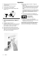
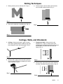
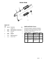
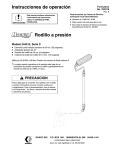
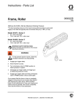
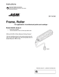
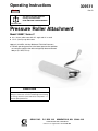
Operating Instructions
309511
Rev. D
Parts
This manual contains important
warnings and information.
READ AND KEEP FOR REFERENCE.
INSTRUCTIONS
Pressure Roller Attachment
Model 245907, Series C
D 9 in. (23 cm) roller frame with 45_ angle and 12 in. reach
D 1/2 in. (13 mm) nap roller cover
3600 psi (24.8 MPa, 248 bar) Maximum Fluid Inlet Pressure *
* The best operating pressure is the lowest pressure that provides
an even paint supply to the roller and typically does not exceed
300 psi (2.1 MPa, 21 bar).
CAUTION
Never leave water in the pump, gun, or pressure roller.
Doing so could cause corrosion and damage from freezing.
For storage, flush the system with Graco Pump Armort or
mineral spirits/paint thinner.
GRACO INC.
P.O. BOX 1441
MINNEAPOLIS, MN
ECOPYRIGHT 2002, GRACO INC.
Graco Inc. is registered to I.S. EN ISO 9001
55440–1441
Warnings and Cautions
WARNING
INSTRUCTIONS
EQUIPMENT MISUSE HAZARD
Misuse can cause the equipment to rupture or malfunction and result in serious injury.
To help prevent injury
D Do not modify the extension tube or roller frame or use parts not designed for this
equipment.
D Do not use 1,1,1–trichloroethane, methylene chloride, other halogenated hydrocarbon
solvents or fluids containing such solvents in this or any other pressurized aluminum
equipment. Such use could result in a chemical reaction, with the possibility of explosion.
FIRE AND EXPLOSION HAZARD
Improper grounding, poor ventilation, open flames or sparks can cause a hazardous
condition and result in a fire or explosion and serious injury.
To help prevent injury from fire or explosion
D Provide fresh air ventilation to avoid the buildup of flammable fumes from flushing fluids or
the coating being applied.
D Keep the application area free of debris, including solvent, rags, and gasoline.
FLUID INJECTION HAZARD
If high-pressure fluid pierces your skin, the injury might look like “just a cut”. But it is
a serious wound. Get immediate medical attention.
To help prevent injection
D Keep your hands and body away form the roller frame when flushing. High pressure fluid
emitted from the holes in the frame could cause an injection injury.
D Always relieve pressure before you check or repair leaks and when you turn off pump or
stop painting.
D Never use components rated less than system Maximum Working Pressure.
ELECTROCUTION HAZARD
Failure to observe the electrical hazards described below could result in serious injury,
including burns or electrocution.
To help prevent harmful electrical shock
D Avoid contact with power lines.
D Follow all grounding instructions in your separate pump and gun instruction manual, and
comply with all local, state, and national fire, electrical, and safety regulations.
D Use only MAGNUM or Graco paint hoses.
2
309511
Pressure Relief Procedure
WARNING
To help prevent injection injuries,
follow this procedure whenever
you stop painting.
psi/MPa/bar
1. Engage gun trigger safety latch.
3. Turn prime/spray valve to the PRIME to relieve
pressure in system.
4. Remove gun trigger safety latch. Trigger gun to
relieve any pressure in hose.
5. Engage gun trigger safety latch. Keep pump
prime/spray valve in PRIME position until you paint
again.
2. Shut off power to pump.
309511
3
Operation
1. Follow pump priming instructions prior to
assembling roller.
2. Do not put tip and guard on spray gun.
3. Turn prime/spray valve to SPRAY.
4. Turn pressure control to lowest setting or roller
symbol. Fig. 1.
10. Remove gun trigger safety latch. Trigger gun.
Roll surface.
NOTE: Trigger the gun briefly only when you need
more paint. Determine how often you must trigger
the gun to maintain an even paint supply to the
roller.
The best operating pressure is the lowest pressure
that provides an even paint supply to the roller and
typically does not exceed 300 psi (2.1 MPa, 21
bar).
11. Increase pump pressure only if triggering gun
cannot supply enough paint for your rolling speed.
Pressure Relief
Procedure, page 3.
Fig. 1
5. Remove gun trigger safety latch. Trigger the gun
once until paint comes out of gun. Release
trigger.
6. Engage gun trigger safety latch.
7. Assemble the pressure roller as shown in the Parts
Drawing, page 7. Make sure the gasket (6) is in
place in bottom of roller frame as shown.
8. Attach pressure roller assembly to spray gun.
9. Rest roller on flat surface and align gun with roller.
Tighten nut with wrench while keeping gun and
roller aligned as pictured below.
4
309511
12. Whenever you stop painting, relieve the
pressure, and elevate roller end of extension tube
to prevent paint from draining out.
Flush the pump, gun, and pressure roller immediately
after each use to prevent paint from drying in the
pressure roller and damaging it. (Cleaning, page 6).
Rolling Techniques
1. Rolling vertically, roll out the letter “M”. (Fig. 2.)
3. Finish with light, vertical strokes until the entire
area has been covered, evenly. (Fig. 4.)
Fig. 2
2. Cross roll, horizontally, to spread paint. (Fig. 3.)
Fig. 4
Fig. 3
Ceilings, Walls, and Woodwork
1. Ceilings: Using a paint brush, apply a starting
row of paint approximately the width of your paint
brush where the walls and ceiling meet. (Fig. 5.)
1. Woodwork & Walls: Using a brush, paint
woodwork first. Apply a starting row of paint
approximately the width of the paint brush around
the woodwork and where the walls meet the
ceiling. (Fig. 7.)
Fig. 5
2. With the roller, apply paint to the ceiling, working
the short way of the room and applying as wide a
strip as possible. (Fig. 6.)
Fig. 7
2. With the roller, apply paint to the walls, following
the Roller Techniques described above. (Fig. 8.)
Fig. 6
Fig. 8
309511
5
Cleaning
This is the procedure for flushing the pressure roller. The pump and gun you are using may have additional flushing
steps, such as cleaning filters and screens. See the pump and gun flushing instructions.
NOTE: Leave the pressure roller attached to the gun for this procedure.
4. Place roller frame (1) in paint pail. Be sure the
holes in roller frame (1) are facing inside the paint
pail.
Pressure Relief
Procedure, page 3.
1. Relieve the pressure.
2. Remove roller cover (7) and diffuser (4) from roller
frame as follows (Parts Drawing, page 7):
a. Using your thumb, press down on clip (5) to
release end caps (2 & 3), diffuser (4) and roller
cover (7) into a pail.
b. Remove roller cover (7) from diffuser (4).
c.
Pull end caps (2 & 3) off diffuser (4).
Disassemble.
3. Clean roller cover (7), caps (2 &3) and diffuser (7)
with water or a compatible fluid for oil–based
materials.
5. Prime pump with water or flushing fluid for
oil–based materials. Use the lowest pump priming
pressure setting.
6. Turn prime/spray valve to SPRAY.
NOTE: Perform Step 7 at the lowest pressure
possible.
7. Trigger gun until flushing fluid begins to dilute the
paint.
8. Place roller frame (1) in another bucket and
continue flushing until fluid coming out of the roller
frame (1) is clear.
9. Shut off the pump. Turn prime/spray valve to
PRIME.
Storage
If you are going to store the airless equipment for an extended period of time after flushing with water-base fluid,
flush again with Graco Pump Armor or mineral spirits/paint thinner. Leave the fluid in the system during storage.
6
309511
Roller Parts
4
3
1
5
2
7
6, 9
ti2135b
Parts List
Ref.
No.
Part No.
Description
1
2
3
4
245999
246277
15B065
FRAME, roller
CAP, end (includes seal and retainer)
CAP, end (includes seal and retainer)
DIFFUSER
1
1
1
2
5
6
197106
115524
o–ring)
CLIP, roller
GASKET
1
1
1
7
186678
ROLLER, cover, 9 inch,
1/2 in. (13 mm) nap
1
SWIVEL, fitting
1
9
197118
Qty.
Additional Roller Covers
For the best coverage it is important to choose the
right roller cover nap for the surface you are rolling.
For rougher surfaces choose a thicker nap. Use a
thinner nap on smooth surfaces.
Part No.
Nap Size
243063 9 in. (23 cm);
1/2 in. (13 mm)
243064 9 in. (23 cm);
3/4 in. (19 mm)
243065 9 in. (23 cm);
1-1/4 in. (32
mm)
Surface Texture/
Example
Material
Smooth/ metal,
medium
wood, trim, drywall
Rough/
cement, brick
heavy
Extra–rough/
cement block, textured walls, ceilings
heavy
309511
7
Limited Warranty
Graco Inc. warrants to the original retail purchaser (other than for purposes of resale or rental) all equipment
manufactured by Graco and bearing its name to be free from defects in material and workmanship if operated
in accordance with Graco’s printed recommendations and instructions. This warranty applies for one year from
the date of purchase.
This warranty does not cover and Graco shall not be liable for general wear and tear, or any malfunction,
damage or wear caused by improper use, accidents, user negligence, use of non-Graco component parts or
service or repair performed by anyone other than a Graco authorized service center.
IMPLIED WARRANTIES, INCLUDING THOSE OF MERCHANTABILITY AND FITNESS FOR A PARTICULAR
PURPOSE, ARE LIMITED TO ONE YEAR FROM THE DATE OF ORIGINAL PURCHASE.
GRACO SHALL NOT IN ANY EVENT BE LIABLE FOR ANY INCIDENTAL, INDIRECT, OR CONSEQUENTIAL
LOSS, DAMAGE OR EXPENSE OF ANY KIND, WHETHER FROM BREACH OF THIS WARRANTY OR ANY
OTHER REASON. Some states do not allow the exclusion or limitation of incidental or consequential damages,
so the above limitation or exclusion may not apply to you.
To make a claim under this warranty, return the product with proof of purchase, transportation prepaid, to any
Authorized Graco Service Center. Graco’s Authorized Service Center, at its option, will either repair or replace
the product and return it to you, postage prepaid. A listing of Authorized Graco Service Centers is enclosed
with this product. You may also find the nearest Authorized Graco Service Center by calling 1–888–541–9788
or by visiting our website at www.graco.com.
This warranty gives you specific legal rights and you may also have other rights which may vary from state to
state.
All written and visual data contained in this document reflect the latest product information available at the time of publication.
Graco reserves the right to make changes at any time without notice.
GRACO INC.
P.O. BOX 1441
MINNEAPOLIS, MN
www.graco.com
PRINTED IN USA 309511 4/2002, Revised 4/2003
8
309511
55440–1441