1
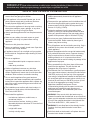
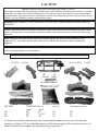
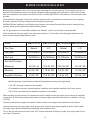
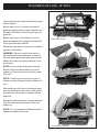
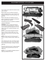
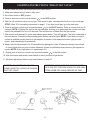
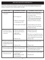
INSTALLATION AND OPERATING
INSTRUCTIONS
DE
SIGN
C
GOLDEN BLOUNT “TEXAS FLAME II” GAS LOGS
E
D
FOR VENT-FREE
OR VENTED INSTALLATIONS
RTIFIE
®
NATURAL GAS OR L.P.
18“ - 24“ & 30“ SIZE SETS
Warning: If the information in this manual is
not followed exactly, a fire or explosion may
result causing property damage, personal
injury or loss of life
• Do not store or use gasoline or other
flammable vapors or liquids in the
vicinity of this or any other appliance.
• What to do if you smell gas:
- Do not try to light any appliance.
The Golden Blount vent-free gas
log sets comply with the National
Safety Standards and are tested
and design certified by CSA to
ANSI Z21.11.2-2000, unvented
heaters Z21.60a-2000 decorative
gas appliances for installation only
in a woodburning, masonry or UL
listed manufactured fireplace or in a
Golden Blount or any other CSA
approved vent-free fireplace. This
product may be burned with the
fireplace damper in either a closed
or open position.
MANUFACTURED BY:
INC.
4301 WESTGROVE DRIVE
ADDISON, TX. 75001
- Do not touch any electrical switch;
do not use any phone in your
building.
- Immediately call your gas supplier
from a neighbor’s phone.
- If you cannot reach your gas
supplier, call a fire department.
- Installation and service must be
performed by a qualified installer,
service agency or the gas supplier.
Warning: Logs must be arranged so that the
flames only touch bottom back log or front
ember log. Flames must not touch any other
log in set or any part of firebox.
This is an unvented gas-fired heater. It
uses air (oxygen) from the room in which
it is installed. Provisions for adequate
combustion and ventilation air must be
provided.
IMPORTANT! Read all instructions carefully before starting installation. Failure to follow these
instructions may result in property damage, personal injury or possible loss of life
SAFETY AND GENERAL INFORMATION
correct gas type for your appliance. Do not
• Use
convert from one gas type to another.
this appliance is for use with Propane gas, do not
• Ifplace
propane supply tank(s) inside any structure.
outside air ducts and/or ash dumps in the fireplace
• Any
shall be permanently closed at time of appliance
installation.
the gas appliance and its individual shut off
• Disconnect
valve from the gas supply piping system during any
Locate propane supply tank(s) outdoors.
pressure testing of that system at test pressures in
excess of 1/2 psig. (3.5kPa).
not use the appliance for burning trash or cooking.
• Do
Never place matches, paper, garbage, or any other
the appliance from the gas supply piping
• Isolate
system by closing its individual manual shut off valve
material on top of logs or logs into flame.
operate appliance with front fireplace screens
• Always
closed.
sure any safety wire mesh screen or guard
• Make
removed for servicing is in place before running
during any pressure testing of the gas supply piping
system at test pressure equal or less than 1/2 psig.
not use any type of aftermarket blower that fits
• Do
inside the fireplace. Drafts created by these type of
appliance.
blowers may cause sooting.
•
run appliance in small, closed room. Open door
• Never
into next room to help ventilate.
appliance shuts off, do not relight until you provide
• Iffresh
outside air. If appliance keeps shutting off, have
Never burn with glass doors closed.
off appliance and let cool before servicing. Only a
• Turn
qualified service person should install, service, and
repair appliance.
the appliance before use and at least annually
• Inspect
by a professional service person. Frequent cleaning
it serviced.
may be required due to excess lint from carpeting,
bedding material, etc. It is important that control
compartment, burner and circulating air passage of the
appliance be kept open.
• Do not run appliance:
- where flammable liquids or vapors are used or
stored.
operated for the first time, there will be some
• When
smell from the appliance. This will diminish and
- under dusty conditions
disappear after a few hours of operation.
of appliance becomes very hot when
• Surface
operating. Keep children and adults away from hot
National Gas Fuel Code defines a confined space
• The
as a space whose volume is less that 50 cubic feet per
surface. Appliance will remain hot for some time after
shutdown. Allow surface to cool before touching.
1000 BTU per hour (4.8m3 per kw) of the aggregate
input rating of all appliances installed in that space and
an unconfined space as a space whose volume is not
less that 50 cubic feet per 1000 BTU per hour (4.8m3
per kw) of the aggregate input rating of all the
appliances installed in that space. Rooms
communicating directly with the space in which the
appliances are installed through openings not
furnished with doors, are considered a part of the
unconfined space.
not use this appliance if any part has been
• Do
submerged under water. Immediately call a qualified
technician to inspect the appliance and to replace any
part of the control system and gas control which has
been under water.
installation must conform with local codes or, in
• The
the absence of local codes, with the National Gas
Fuel Code, ANSI Z223.1.
• Never install the appliance:
if the area in which the heater may be
• WARNING:
operated is smaller than that defined as an unconfined
- in a bedroom, bathroom, mobile home, or
recreational vehicle.
space, provide adequate combustion and ventilation air
by one of the methods described in the National Gas
Fuel Code. ANSI Z223.1, 1992, section 5.3.
- where curtains, furniture, clothing, or other
flammable objects are less than 42” from the front
of the appliance.
Do not allow fans to blow directly into the
• WARNING:
fireplace. Avoid any drafts that alter burner flame
- in high traffic areas.
patterns.
shall not be burned in a fireplace where an
• Solid-fuels
unvented room heater is installed.
- in windy or drafty areas.
2
CAUTION
NOTE! CARBON MONOXIDE POISONING MAY LEAD TO DEATH.
Early signs of carbon monoxide poisoning resemble the flu, with headache, dizziness and/or nausea. If you have
these signs, the heater may not be working properly. Get fresh air at once! Have heater serviced. Some people pregnant women, persons with heart or lung disease, anemia, those under the influence of alcohol, those at high
altitude - are more affected by carbon monoxide than others.
WARNING: ANY CHANGES TO THIS HEATER OR ITS CONTROLS CAN BE DANGEROUS AND CAN VOID
WARRANTY.
Children and adults should be alerted to the hazards of high surface temperature and should stay away to avoid
burns or clothing ignition. Young children should be carefully supervised when they are in the same room as the
appliance.
Note: Installation and repair should be done by a qualified person well trained in the installation of such
appliances. You may need a building permit from your local Building Commissioner before installing this
appliance.
Any safety screen or guard removed for servicing an appliance must be replaced prior to operating the heater. Do
not burn with glass doors in a closed position.
GOLDEN BLOUNT VENT-FREE LOG SET COMPONENT PARTS
18" SETS
24" & 30" SETS
5-LOGS
7-LOGS
BURNER ASSEMBLY
ELBOW
CLAMP
GLOWING EMBERS
CONNECTOR TUBE
BLACK ROCK
SET SIZE
FIREPLACE WIDTH
FRONT
18"
24"
30"
24"
30"
36"
DEPTH
OPENING HEIGHT
14"
16"
16"
20"
21"
21"
BACK
18"
21 1/2"
30"
If a hood is not installed, there must be only noncombustible material from the top of the fireplace
opening to a height of 20". A combustible mantel or shelf must be at least 39" up from the opening. If a
hood is installed on the fireplace, the clearance can be reduced to 7".
3
BURNER SYSTEM INSTALLATION
Before starting installation, find out if local and state codes approve vent-free gas logs. If unvented gas logs are not
approved, the installation must be made with the fireplace damper partially open and locked to assure the minimum
vent area required by local codes or the National Gas Fuel Code (ANSI Z223.1-latest edition). Use the damper clamp
provided.
Clean the firebox thoroughly. In the future, frequent cleaning may be required due to excessive lint from carpeting
and other materials. All burner components must always be kept clean.
WARNING: Before installing in a solid fuel burning fireplace, the chimney flue and firebox must be cleaned of soot,
creosote, ashes and loose paint by qualified chimney cleaner.
If a 1/2“ gas supply line is not already installed in the fireplace, a call to your plumber is recommended.
Check to make sure the gas supply is the same type (natural or L.P.) as listed on the rating plate attached to the
burner. Note the approved gas pressure chart.
Model
GB-TFII-18
GB-TFII-18 GB-TFII-24/30 GB-TFII-24/30
Gas Type
Natural
L.P.
Natural
L.P.
Max Input
30,000btu/hr
30,000btu/hr
38,000btu/hr
35,000btu/hr
Min Input
19,000btu/hr
26,000btu/hr
22,700but/hr
28,500btu/hr
Maximum
10.5 IN. wc
14.0 IN. WC
10.5 IN. WC
14.0 IN. WC
Minimum
5.0 IN. WC
11.0 IN. WC
5.0 IN. WC
11.0 IN. WC
Regulator Pressure
3.5 IN. WC
10.0 IN. WC
3.5 IN. WC
10.0 IN. WC
Gas Inlet Pressure
Manifold pressure check should be made with the appliance burning in the high setting.
A 1/8“ NPT test plug is located on the regulator.
LP Installations require an external regulator in addition to the regulator installed in the burner system.
The LP tank could explode if the additional regulator is not installed.
When checking gas inlet pressure, the appliance must be isolated from the gas supply line by closing its individual
manual shut off valve during and pressure testing of the gas supply at test pressures equal to or less then 1/2 psig.
(3.5 KPA)
Centrally locate the burner/grate unit inside the firebox. Position burner/grate unit towards rear of the firebox.
Connect the burner to the gas supply using the connector tube and brass elbow supplied in the kit. Some installations may require different fittings that are available from hardware stores.
Turn on the gas with the burner valve in the “OFF” position and check all fittings for leaks using soapy water. Do not
use a flame to leak test.
4
PLACEMENT OF LOGS - 18” SETS
Front ember log sits under front ember burner
tube as shown.
Bottom back log is to be placed on back of
grate and against burner support brackets as
illustrated. Notches in bottom log will go over
grate bar.
Bottom front log is to be placed on front of
grate and against front uprights as illustrated.
Front log should be centered.
EMBER BURNER TUBE
EMBER LOG
Remaining logs are to be placed in numbered
notches as illustrated.
WARNING: Failure to position the parts in
accordance with these diagrams or failure to
use only parts specifically approved with this
heater may result in property damage or personal injury.
1B
NOTE!: Logs must be arranged so that the
flames only touch bottom back log or front
ember log. Flames must not touch any other
log in set.
2B
2F
1F
NOTE!: Flames must not touch any part of
firebox housing. (Damper handle, firebox roof
etc.)
After positioning the logs on the burner grate,
pour the black lava rock in front of the ember
log and around the sides to enhance the appearance.
Spread the allotted amount of ember material
over the ember pipe positioned in the front
ember log.
NOTE!: Do not exceed the allotted amount of
embers provided with the set.
GLOWING EMBER MATERIAL
5
PLACEMENT OF LOGS - 24” & 30” SETS
Front ember log sits under front ember burner
tube as shown.
Bottom back log is to be placed on back of
grate and against burner support brackets as
illustrated. Notches in bottom log will go over
grate bar.
Bottom front log is to be placed on front of
grate and against front uprights as illustrated.
Front log should be centered.
EMBER BURNER TUBE
EMBER LOG
Remaining logs are to be placed in numbered
notches as illustrated.
WARNING: Failure to position the parts in
accordance with these diagrams or failure to
use only parts specifically approved with this
heater may result in property damage or personal injury.
T2
1B
2B
NOTE!: Logs must be arranged so that the
flames only touch bottom back log or front
ember log. Flames must not touch any other
log in set.
1F
2
NOTE!: Flames must not touch any part of
firebox housing. (Damper handle, firebox roof
etc.)
After positioning the logs on the burner grate,
pour the black lava rock in front of the ember
log and around the sides to enhance the appearance.
Spread the allotted amount of ember material
over the ember pipe positioned in the front
ember log.
NOTE!: Do not exceed the allotted amount of
embers provided with the set.
GLOWING EMBER MATERIAL
6
3F
4F
FOR YOUR SAFETY READ BEFORE LIGHTING
WARNING: If you do not follow these instructions exactly, a fire or explosion may result causing property damage,
personal injury or loss of life.
A. This appliance is equipped with a push-button piezo ignition device which automatically lights the pilot. If the piezo
fails to ignite the pilot, then follow the lighting instructions for lighting the pilot with a match.
B. BEFORE LIGHTING smell all around the appliance for gas. Be sure to smell next to the floor because some gas is
heavier than air and will settle to the floor.
WHAT TO DO IF YOU SMELL GAS:
Do not try to light any appliance
Do not touch any electrical switch. Do not use any phone in your building.
Immediately call your gas supplier from a neighbor’s phone. Follow the gas supplier’s instructions.
If you cannot reach your gas supplier, call the fire department.
C. Use only your hand to push in or turn the gas control knob. Never use tools. If the knob will not push in or turn by
hand, do not try to repair it, call a qualified service technician. Force or attempted repair may result in a fire or
explosion.
D. Do not use this appliance if any part has been under water. Immediately call a qualified service technician to
inspect the appliance and to replace any part of the control system and any gas control which has been under
water.
LIGHTING INSTRUCTIONS
1. STOP! Read the safety information previously listed above.
2. Push in gas control knob slightly and turn clockwise
to the OFF position.
NOTE: Knob cannot be turned from PILOT to OFF unless knob is pushed slightly. Do not force.
3. Wait five (5) minutes to clear out any gas. Then smell for gas, including near the floor. If you smell gas, STOP!
follow “B” in the safety information listed above. If you don’t smell gas, go to the next step.
4. Find Pilot - follow metal tube from gas control. The pilot is located on the front side of burner in the center.
to the PILOT position.
5. Turn knob on gas control counterclockwise
Push in control knob all the way and hold in. While still holding the control knob, press in the ignitor pushbutton
several times. This will cause a spark at the pilot burner which will ignite the pilot flame. Continue to hold the
control knob in for about one (1) minute after the pilot is lit. Release the knob and it will pop back out. Pilot should
remain lit. If it goes out, repeat steps 1-5.
If knob does not pop out when released, stop and immediately call your service technician or gas supplier.
If pilot does not stay lit after several tries turn the gas control knob to OFF and call your service technician or
gas supplier.
6. Turn the gas control knob counterclockwise to
ON.
NOTE: The gas control knob has two settings. With the gas control knob all the way to the ON position, the
log is set on high, and with the control knob approximately half way between PILOT and ON the unit is on low.
You can see the difference in the flame height.
TO TURN OFF GAS TO APPLIANCE
Push in gas control knob slightly and turn clockwise
to OFF. Do not force.
IGNITOR
GAS CONTROL KNOB
PILOT BURNER
IGNITOR
7
LIGHTING INSTRUCTIONS “MILLIVOLT VALVE”
1. STOP! Read the safety information previously listed above.
2. Make sure manual shutoff valve is fully open.
3. Set rocker switch to OFF position.
4. Press in and turn control knob clockwise
to the OFF position.
5. Wait five (5) minutes to clear out any gas. Then smell for gas, including near the floor. If you smell gas,
STOP! follow “B” in the safety information on page 7. If you don’t smell gas, go to the next step.
to the PILOT position. Press in control knob for (5)
6. Press in and turn control knob counterclockwise
seconds. NOTE: If lighting this unit for the first time after hooking up to gas supply the control knob may
need to be pressed in for up to 30 seconds. This will allow air to bleed from the gas system.
7. With control knob pressed in, press and release ignitor button. This will light pilot. The pilot is attached to
the main burner. If needed, keep pressing ignitor button until pilot lights. NOTE: If pilot does not stay lit,
contact a qualified service person or gas supplier for repairs. Until repairs are made, light pilot with
match, (see manual lighting procedure).
8. Keep control knob pressed in for 30 seconds after lighting pilot. After 30 seconds release control knob.
• If control knob does not pop out when released, contact a qualified service person or gas supplier for
repairs. NOTE: If pilot light goes out, repeat steps 4-8
9. Slightly push in and turn control knob counterclockwise
to the ON position.
10. Wait one minute and switch rocker switch to the on position to light burner.
11. Set flame adjustment knob to any level between HI and LO.
CAUTION: DO NOT TRY TO ADJUST
FLAME HEIGHT BY USING THE MANUAL
SHUT OFF VALVE.
WARNING: MAKE SURE THE ROCKER SWITCH
IS IN THE OFF POSITION WHEN YOU ARE AWAY
FROM HOME FOR LONG PERIODS OF TIME.
8
TO TURN OFF GAS TO APPLIANCE “MILLIVOLT VALVE” CONT.
SHUTTING OFF HEATER
1. Turn control knob clockwise
to the OFF position.
2. Set rocker switch to OFF position
Shutting off burners only (pilot stays lit)
You may shut off burner and keep the pilot lit by doing one of the following.
1. Turn control knob clockwise
to the PILOT position.
2. Set rocker switch to OFF position.
3. Turn remote control to OFF position.
MANUAL LIGHTING PROCEDURE
1. Follow steps 1 through 6 under lighting instructions.
2. Depress control knob and light pilot with match or lighter.
3. Keep control knob press in for 30 seconds after lighting pilot. After 30 seconds, release control knob.
Now follow step 9 lighting instructions.
12222222222223
4
5
4
5
4
5
4
5
4
5
4
5
4
5
67777777777778
LIMITED WARRANTY
Golden Blount Gas Logs are warranted against defective materials and/or
workmanship for as long as you own them. Burner Assembly is guaranteed for five
years from date of purchase. ODS Pilot Assembly and valve are covered for one
year.
This warranty does not cover parts subjected to misuse, abuse, improper handling or
improper installation. The GB warranty specifically excludes any liability for indirect,
incidental or consequential damage to property.
Defective logs or defective parts should be returned to your dealer or to the factory
prepaid with a copy of your sales receipt. Defective parts will be repaired or replaced
at the factory’s option and returned to you prepaid.
GOLDEN BLOUNT INC. - 4301 WESTGROVE DRIVE - ADDISON, TX 75001
9
PARTS LIST
18
2
6
13
1
8
7
16
19
17
14
15
22
21
10
24
9
3
20
11
4
12
23
5
TO ORDER PARTS CALL OR WRITE: GOLDEN
BLOUNT INC. • 4301 WESTGROVE DR.
ADDISON, TX 75001 • (972) 250-3113
ITEM
1
2
3
4
5
6
7
8
9
10
11
12
13
14
15
16
17
18
19
20
21
22
23
24
25
26
QUANTITY
1
1
1
1
1
1
1
1
1
1
1
1
1
1
1
1
1
1
1
1
1
1
1
1
1
1
DESCRIPTION
TF-II-18 TOP LEFT LOG
TF-II-18 TOP RIGHT LOG
TF-II-18 BOTTOM BACK LOG
TF-II-18 BOTTOM FRONT LOG
TF-II-18 FRONT EMBER LOG
TF-II-24/30 MIDDLE LEFT LOG
TF-II-24/30 MIDDLE RIGHT LOG
TF-II-24/30 LEFT FRONT LOG
TF-II-24/30 RIGHT FRONT LOG
TF-II-24/30 BOTTOM BACK LOG (SPECIFY SIZE)
TF-II-24/30 BOTTOM FRONT LOG (SPECIFY SIZE)
TF-II-24/30 FRONT EMBER LOG
MAIN BURNER (SPECIFY MODEL AND GAS TYPE)
PILOT ASSEMBLY O.D.S. (SPEC. MODEL AND GAS TYPE)
PIEZO IGNITOR
CONTROL VALVE (SPECIFY MODEL AND GAS TYPE)
IGNITOR WIRE
GAS REGULATOR (SPECIFY MODEL AND GAS TYPE)
BURNER ORIFICE (SPECIFY MODEL AND GAS TYPE)
CONNECTOR TUBE
DAMPER CLAMP
1/2" MPT X 3/8“ FLARE 90 DEGREE ELBOW
BLACK LAVA ROCK
GLOWING EMBER MATERIAL
ROCKER SWITCH (NOT SHOWN) MILLIVOLT MODEL
PUSH BUTTON IGNITOR (NOT SHOWN) MILLIVOLT MODEL
10
TROUBLESHOOTING REFERENCE
With Proper installation and maintenance, your new Gas Appliance should provide years of trouble free
service. If you do experience a problem, this guide will assist a CERTIFIED SERVICE PERSON in the
diagnosis of problems and the corrective action to be taken.
SYMPTOM
1. Pilot will not light with
Piezo ignitor
POSSIBLE CAUSES
A. Main shutoff valve closed.
B. Air in the gas line.
C. ODS Pilot orifice plugged,
not allowing gas to flow.
2. Pilot will not stay lit
after following lighting
instructions.
3. No gas to main burner
with pilot flame burning
and valve turned to On
position.
CORRECTIVE ACTION
1. Make sure that the shutoff valve
located on the pipe supplying gas to
the fireplace is open.
1. Light a match, turn valve knob to
PILOT position and depress. Keep
match near pilot burner assembly.
1. Replace the ODS Pilot assembly.
D. No gas supply to the fireplace
1. Check plumbing to see if gas line
has been hooked up to gas supply
2. Propane tank empty
A. Defective thermocouple
B. Thermocoupler fitting not
tight in valve
C. Weak pilot flame
1. Replace thermocouple.
1. Carefully tighten fitting.
D. Defective valve.
1. Pilot flame must engulf thermocouple.
Clean and/or adjust pilot for maximum
flame impingement on thermocouple.
1. Replace valve.
A. Plugged main burner orifice.
1. Carefully remove and clean orifice.
B. Defective valve.
2. Replace valve.
4. Soot accumulating on logs. A. Flame touching log surface
1. Rearrange the logs so that flames do
not touch the logs at any point.
5. Both main burner and
Pilot flame shuts off.
1. Open outside door or window slightly.
A. Insufficient oxygen to
operate heater.
B. Drafty conditions around
burner assembly
11
1. Eliminate draft.