1
INTERAaM
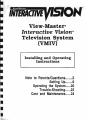
View-Master®
Interactive Vision™
Television System
(VMIV)
Installing and Operating
Instructions
Note to Parents/Guardians
Setting Up
Operating the System
Trou ble·Shooting
Care and Maintenance
2
6
20
22
24
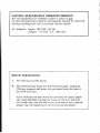
CAUTION-ELECTRICALLY OPERATED PRODUCT:
Not recommended for children under 3 years of age.
As with all electrical products, precautions should be observed
dUring handling and use to prevent electric shock.
AC Adapter: Input: 120 VAC, 60 Hz.
Output: 16 VAC, C.T., 800 rnA.
System Requirements:
1. The VCR must be VHS format.
2. The VCR must have
AUDIO OUT and VIDEO OUT jacks. Almost all
VCRs are equipped with these, but you should check the back of
your VCR to be sure.
If your VCR does not have AUDIO OUT and VIDEO OUT jacks, please
call 1-800-292-9843, between the hours of 7:30 a.m. and 4:00
p.m. Pacific time, and you will be sent. at no cost to you, a special
adapter that will enable you to connect and use the system.
I
I
I
I
I
I
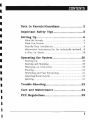
CONTENTS
Note to Parents/Guardians
2
Important Safety Tips
5
Setting up
6
What We Provide
6
What You Provide
7
Step- By-Step Installation
8
Abbreviated Instructions (for the technically inclined) 9
18
A Note on Stereo
Operating the System
20
Starting Up
Starting and Stopping
Replaying an Interaction
Pausing
Rewinding and Fast Forwarding
Adjusting Sound Levels
Quitting
Trouble-Shooting
I
20
20
20
21
21
21
21
~
22
Care and Maintenance
24
FCC Regulations
25
NOTE TO PARENTS/GUARDIANS
Dear Parents/Guardians:
View-Master® Interactive Vision™ Television System (VMIV)
offers a two-way television viewing experience that's both
entertaining and educational. Your child will play games,
constnlct songs and stories, and respond to questions asked
by his or her favorite TV and movie characters, who will react
differently according to the answers.
To help your child get the most out of VMIV, please read this
booklet completely before you operate the system.
The booklet contains the following major sections:
•
SETTING UP. VMIV connects to your VCR and 1V for a
one-time setup. Once connected, it remains ready to play
and does not interfere with regular 1V and VCR viewing.
Setting up the system is very simple with most video
system configurations. Pages 6-19 contain clear
instructions and diagrams to help you connect VMIV to
your system.
•
OPERATING THE SYSTEM. This section explains briefly
how to start, stop, pause, rewind or fast-forward VMIV.
Each interactive videocassette provides instructions on the
use of the Electronic Controller with its joystick and
buttons. VMIV is an electrically operated product; there
fore, each time your child is ready to play, we recommend
that you switch on your VMIV, VCR and 1V and insert the
interactive videocassette. However, if your child is old
enough to work a VCR, you may wish to go over the
OPERATING section (pages 20-21} with him or her.
It is a good idea to re-read the OPERATING section after
you have played an interactive videocassette a few times.
2
I
I
I
I
I'
I
I
I
NOTE TO PARENTS/GUARDIANS
•
TROUBLE-SHOOTING. In the unlikely event you have a
problem in operating the View- Master® Interactive
Vision™ Television System, this section provides
suggestions for remedying the problem.
We also recommend that you remain with your child the first
time he or she operates the system. That way, you will be
able to share in the child's enjoyment as well as ensure that
everything is working smoothly. We hope you and your family
enjoy View-Master® Interactive Vision™ Television System
and the unique interactive 1V experience it provides.
Please keep these instructions handy for future reference, and
remember to send in your Warranty Registration Card within
ten days of purchase.
If you have any questions or problems that are not answered
in this booklet, please call us at our toll-free customer service
hot line, 1-800-292-9843, between the hours of 7:30 a.m. and
4:00 p.m. Pacific time.
3
4
IMPORTANT SAFETY TIPS
Important Safety Tips
•
Observe Warnings. Read all safety and operating
instructions before operating the system, and all warnings
on system components should be observed.
• Power Sources. The system should be connected only to
the AC Adapter supplied with this product (see SETTING
UP).
•
Object and Liquid Entry. Care should be taken so that
small objects do not fall and liquids are not spilled into
system components.
• Temperature. System components should not be exposed
to extreme heat or cold.
• Ventilation. Your VMIV Video Processor has ventilation
openings in its cabinet to release heat generated during
operation. Blocking these openings can cause heat build
up inside the unit, causing failures that may result in a fire
hazard. For protection, avoid obstructing the ventilation
openings with any foreign objects.
5
SETTING UP
Before you can set up your View- Master® Interactive Vision ™
(VMN} Television System, you should make sure you have
everything you need. Pages 6 and 7 provide this information.
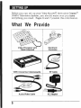
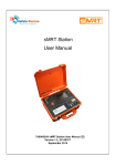
What We Provide
Video Processor with
Cable Attached
VMIV Interactive Videocassette
AudioNideo Cable
6
Electronic
Controller
RF Cable
AC Adapter
•
•
SETTING UP
I
I
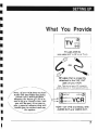
What You Provide
TV with VHF IN
(also called ANT in, RF in, or TV in)
RF cable that is presently
attached to the VHF OUT
jack on your VCR.
I
Note: There are two types of RF connectors,
screw-on and push-on. Either type will worK fine.
Note: if your VCR does not have
Audio Out and Video Out jacks,
please call 1-800-292-9843,
between the hours of 7:30 a.m.
and 4:00 p.m. Pacljic time, and
you will be sent, at no cost to
you, a special adapter that will
enable you to connect and use
the system.
VCR-1/2" VHS (not Beta), with
AUDIO OUT and VIDEO OUT.
7
SETTING UP
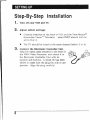
Step-By-Step Installation
1. Turn off your VCR and TV.
2. Adjust
switch settings:
•
Channel switches on the back of VCR and the View-Master®
Interactive Vision™ Television /stem (VMN) should both be
set to 3 or 4.
•
The 1V should be tuned to the same channel (either 3 or 4).
3. Connect the
Electronic Controller Unit.
Take the black cable attached to the front of
the VMN Video Processor, and attach it to
the Electronic Controller Unit with its
joystick and buttons. A small rib has been
added to make sure the plug fits only in one
position. Align the plug carefully.
8
I
I
I
SETTING UP
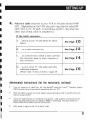
4. Find the cable attached to your VCR at the jack labelled VHF
OUT. (Depending on the VCR, this jack may also be called RF
OUT, OUT to IV, IV OUT, or something similar.) See what the
other end of that cable is attached to.
I
I
I
If the cable connects...
A. ... directly to your 1V
(for stereo lV, see D.
I
below)
See Page
10.
I
B. ... to a cable converter box
See Page
12.
1
-
C. ... to a switch box to which a cable converter
SeePage
box, electronic game or home computer is
also connected
14.
1
-
D. .., to your stereo 1V, with audio and video
cables also attached
I
See Page
16.
(Please read "A Note on Stereo," page 18)
I
Abbrevi'ated Instructions (for the technically inclined)
•
From the viewpoint of signal flow. the View-Master@ Interactive Vision™
(VMIVl should always be positioned immediately after the VCR.
•
When the VMIV is turned off, the RF signal is passed through (via RF IN and RF OUT) to TV
without being modified.
•
Interactive videocassettes are encoded for interactions. Code. graphics. and sound for the
games and other interactions are passed to VMIV for processing. This data travels via
AUDIO/VIDEO (RCA cables) from the VCR to VMIV.
•
VMIV sends its signal to the TV via the RF cable.
Television System
9
SETTING UP
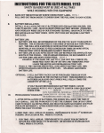
Configuration A:
Your VCR connects directly to your TV.
Your current configuration looks something like this:
~":,:,:,:,.,:":,:,:":,.., :,"""'S
~
~
~
TV
"
d)~..
VHF IN
~
@®~~
OR
......
---
""""""""""""~
~~
Dis~onnect
~"""""""""""""""""~Antenna
da01d}=~~VHFOUT VHFIN~~o~able
this
cable at VCR
~ eAUDIO OUT
~
~ t:!fU
~VIDEO OUT VCR ~~
S
~"""""""""""""""""""
Configuration A, Without VMIV
• Disconnect the cable attached to the VHF OUT jack on the
VCR.
• Attach that cable to the View-Master® Interactive Vision™
Television System as illustrated on the next page.
10
I
I
I
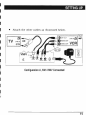
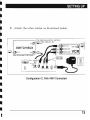
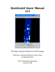
SETTING UP
•
Attach the other cables as illustrated below.
~",..\""",..\""""" ., ., ." """",.." "",.." ,..,~
~ ~O VHF OUT
~~
~~
~ 4'\AUDIO OUT
I
I
VHF INQJJ ~~
~
...
~W1
VCR~
~ <l)VIDEO OUT
I
~
~
~
~"""""""""""""""""~
I
CH. :
LJ (Q) t1)
1 2 3
I
AnI. 0 r I
Cable
Ii]
AUO
RFOUT
RFIN
e
AUDIO IN
JJ,
~
VIDEO IN
m
AC
Configuration A, With VMrV Connected
I
I
I
I
11
'I
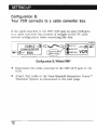
SETTING UP
Configuration B:
Your VCR connects to a cable converter box.
If the cable attached to the VHF OUT jack on your VCR goes
to a cable converter box instead of straight to the 1V. your
current configuration looks something like this:
""""""""""""""""",,~
~~
~ 0I VHF OUT
~~
~ ..,AUDIO OUT
~
VHF IN ~ ~
~~
Antenna
or cable
...
~
~~ <i»VIDEO OUT VCR~~
s...""""""""""""""""",'l
Configuration 8, Without VMIV
•
Disconnect the cable attached to the VHF OUT jack on the
VCR.
• Attach that cable to the View-Master® Interactive Vision™
Television System as illustrated on the next page.
12
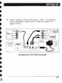
SETTING UP
•
Attach the other cables as illustrated below.
~""""'. " """"""""" . " ,""""'" """"'~ Ant. 0 r
~""""""""~""""""""""~
~ ~VHF OUT
~~
~
~
CABLE IN~~~
CON'VERTER ~~
s~
~tQl0UT BOX
~
s
...
To TV
~ _AUDIO OUT
~ ~ Cable
VHFINtQI~"'"
~
~~ <l)VIDEO OUT VCR~~
~"""""""""""""""""~
~""""""""""""""""""'~
(Must be set to 3 or 4, whichever is
not broadcast in your area)
CH.3
123
ID
AUO
4
e](Q)
RFOUl
~
(Q)
4'\
RFIN
.,
WI
AUDIO IN
VIDEO IN
Conf,iguration '8, With VMIV Connected
I
I
•
I
13
SETTING UP
Configuration C:
Your VCR connects to a switch box.
If the cable attached to the VHF OUT jack on your VCR goes
to a switch box instead of straight to the 1V, your current
configuration looks something like this:
~"""':,.,:,:,:,,",.., :,:,,""",..,:,,'.,. . ,:,:,,":,:,:,:,,~
~
~S
~
~
~
T.TV
From cable converter box, electronic
~~ game, home computer, etc.
IN
~~~
SWITCH BOX
~((JOUT
S
~
~
IN®l~
~~"""""""""""""""""'~
...
,
'\"""""""""""""""""'" Antenna
~~
~ or cable '
~ QJvVHF OUT
VHF IN~ ~ ...
SAS\
~ ..,AUDIO OUT
~s
~
~<iDVIDEOOUT VCR~
s.""""""""""""""""",-'
Configuration C, Without VMIV
•
Disconnect the cable attached to the VHF OUT jack on the
VCR.
•
Attach that cable to the View-Master® Interactive Vision™
Television System as illustrated on the next page.
14
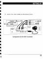
SETTING UP
I
•
~""" ., :,:,:,"'.., :,:,':,:,""'.., ., :,'..,:,:,.., .,:,.,:,..,:" From cable converter box, electronic
~
~
~
~
~
I
I
I
I
I
I
I
I
I
Attach the other cables as illustrated below.
To TV
•
~
~
~
~~ game, home computer, etc.
IN
IQJP~ ,.
~
~ ~O VHF OUT
SWITCH BOX ~
~
~d) OUT
IN ~~
~~"""""""""""""""""""
(Must be switched to VMIV input) .
~ C!DVIDEO OUT
~
~"""""""""""""""""~
CH.: DC) (Q)
li:l
AUD
RFOUT
~ Cable
~~
VHFIN(Q)~~
~ AS.'\AUDIO OUT
~
~II'IJ
VCR~
~
123
~"""""""""""""""""~Ant. or
RF IN
@D
AUDIO IN
e
VIDEO IN
II
w
AC
Configuration C, With VMIV Connected
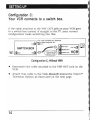
SETTI~JG
UP
Configuration 0: Your VCR connects to a stereo
TV, with audio and video cables also attached.
If the cable attached to the VHF OUT jack on your VCR goes
to a stereo 1V, and you also have audio and video cables
connecting the VCR to the 1V, your current configuration
looks something like this:
~'''''''''''''''''''''''''''''':~
~
~s
~"""""""""""""'''''''''''~
Antenna
~~
~ or cable
~ TV
AUDIO 1
~ t)AUDIO 1 OUT
~
AUDIO 2 IN..,~
~
VHF INlQI~
~tQ;vVHF OUT
INe~
~,6'\~
~
VIDEO
VHF IN6) ~ ...
~
~ 4"\
~
~ \UJAUDIO 2 OUT
~
IN<iD~ ~.II!!!8ii~IBIlIBIlIl!!Z~~~i8Sii1888s4iII~~ <i)VIDEO OUT VCR ~
s.."""""""",,-,,,,,,,,,,~
~""""""""""""""""'-,~
Configuration D" Without VMIV
•
Disconnect the cable attached to the VHF OUT jack on the
VCR. Attach that cable to the View-Master® Interactive
Vision™ Television System as illustrated on the next page.
• Also disconnect the audio
and video cables from the
VCR. Refer to pages 18-19
for a note on how to utilize
these cables to maintain
stereo capability.
16
~i·Wl
!
.......;.:.
~II
&*
I
I
SETTING UP
•
Attach cables as illustrated below. '(Note: To maintain
stereo capability, please read "A Note on Stereo" on
pages 18-19.)
See "A Note
on Stereo" on
page 18.
VMIV CH:
12
AUD
'
LJ
~T ~ ~
AUDIO IN
(i)
VIDEO IN
i
AC
Configuration D, With VMIV Connected
I
17
SETTING UP
A Note on Stereo
No matter what type of stereo configuration you have, you will
be able to use the View-Master® Interactive Vision™
Television System (VMIV) with no problem.
• If your TV has MTS (multi-channel television sound)
capability, broadcast stereo will be transmitted to the TV
through the RF cable as normal.
•
If your stereo or Hi-Fi TV receives its audio and video
signal from the VCR's AUDIO OUT and VIDEO OUT jacks,
then you can install the VMIV as diagrammed on page 17
for normal monaural operation. The VIDEO OUT and one of
the AUDIO OUT signals will be diverted to the VMN, and a
monaural (or MTS) RF signal will be transmitted to the TV.
• To maintain Hi-Fi or stereo capability,
you can purchase two additiona!,
inexpensive RCA V-connector cables
(illustrated at the right) which are
readily available in most consumer
electronics stores. Install them as
illustrated in the diagram on page 19.
18
I
I
SETTING UP
A Note on Stereo
(continued)
~"""""""""""""""""~
~~
~ 0J;;IVHF OUT
~ .4'\AUDIO 1 OUT
~~
s AS.\
~VAUDIO 2 OUT
Ant. or
~ Cab1le
VHF INcQJ ~~
~
~
s
~
~t5.\
VCR~~
~ \!U VIDEO OUT
s..""""""""""""""""",\
VMIV CH':
123
[L]
AUD
EJ
6) ~ ~
AF OUT
RF IN
AUDIO IN
e
VIDEO IN
1m
AC
•
Configuration 0, With VMIV and Stereo
I
I
I
•
When the Y-connectors have been installed, you will have
two different sets of input to the 1V. Your 1V probably
has a switch in the front panel for choosing between these
input options. To operate the VMIV, you will set the 1V to
ANT IN, VHF IN, 1V IN, or RF IN, and you can simply
switch to EXT IN or VIDEO IN for normal stereo
operation.
19
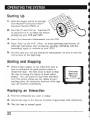
OPERATING THE SYSTEM
Starting U'p
1. Slide
the square switch to tum the
View- Master® Interactive Vision™
Television System (VMIV) on.
2. Tum
the TV and VCR on. Tune the TV
to channel 3 or 4. to match the switch
settings on your VCR and VMIV.
3. Insert
the interactive videocassette into the VCR.
4. Press
"Play" on the VCR. (Note: In these operating instructions. all
videotape operations. such as playing. pausing. rewinding. and fast
forwarding. apply to controls on your VCR.)
5. The first
time you use any interactive videocassette. be sure to view the
instructions at the beginning.
Starting and Stopping
•
Yellow stripes appear on the video from time to
time as indicators for good points to start or
restart the tape. The best place to start or stop
the tape is during the display of these yellow
stripes. You can start the tape from anywhere.
but if the yellow stripes are not visible at your
starting point. the interactive features of the tape
may not function immediately.
Yellow stripes
appear at the
edges of your
TV screen
Replaying an Interaction
1. Find
the interaction you want to replay.
2. Rewind
3. Play
20
the tape to the first set of yellow stripes before that interaction.
the tape at normal speed.
-
-
- - - - -
OPERATING THE SYSTEM
Paus,ing
•
The best place to pause is when you can see the yellow stripes: the
system will function normally when you resume play. If you pause at
other places on the tape. some interactive features of the tape may be
temporarily suspended. Remember. pausing should not be used
frequently. because it will gradually degrade any videotape.
Rew'inding and Fast Forwarding
•
The yellow stripes that appear on the video from time to time prOVide a
starting point to replay an interaction. If you fast-forward or rewind
the tape to a point where the yellow stripes are visible. then the
interaction that starts after that stripe display will work normally.
•
To replay the entire video. you should rewind to the first set of yellow
stripes.
•
You can rewind or fast forward to a favorite interaction by searching
until you see the yellow stripes on the screen just before that
interaction begins.
Adjusting Sound Levels
•
Some VCRs may require a simple adjustment to make the sound levels
equal. The audiO switch (on the back of the VMN Video Processor) is
factory-set to audio level 1. If dUring play you notice a .marked
difference in volume (for example. if the sound is loud and then too
soft), try an audio switch setting of 2 or 3.
Quitting
you are done. rewind the videocassette the entire way, eject the tape.
• Ifplace
it in its protective sleeve. and turn off the VMIV. Remember
rewinding completely will prolong the life of any videocassette.
•
Your TV and VCR will now operate normally.
21
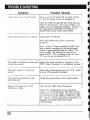
TROUBLE-SHOOTING
Symptom
Possible Remedy
Make sure the TV and VCR are both turned
on and the power cords are plugged in.
I get no picture on my IV screen.
Turn the VMIV on and off; see if this has any
,effect on the picture. If it has no effect, your
cables are not connected properly. Return to
the appropriate SEITING UP diagram to
double-check your cable connections.
I
I
I get a clear picture but no sound.
I
Check your TV volume.
The audio cable may not be connected
properly.
Note: If your TV has a setting for HRC, this
has a special encoding for the audio signal
which is incompatible with the VMIV. Do
not use HRC; use settings for antenna or
cable (CATV). The receiving mode on your
,TV must be set to channel 3 or 4.
The audio is sometimes louder and
Isometimes quieter.
I
Adjust the audio switch (on the back of the
VMIV Video Processor) to a different setting.
The audio makes a "crackling"
sound.
Adjust the tracking knob on your VCR Refer
to your VCR manual for details.
The sound is sometimes on and
sometimes off
Check the connections of the audio cables.
Regular TV programs or VCR
videos don't play.
Turn off the VMIV Video Processor.
Check the configuration of the following
cables: {I) The cable from VHF OUT on the
,VCR to RF IN on the VMIV: and (2) the cable
from RF OUT on the VMIV to VHF IN on the
TV. (Return to the appropriate SE1TING UP
diagram to double-check your cable
connections.)
22
I
I
I
I
I
I
I
TROUBLE-SHOOTING
Symptom
Possible Remedy
VMN is turned off. but my 1V only
works on Channel 3.
Turn off your VCR.
Make sure the VMIV Video Processor is
turned on.
I The interactive tape plays, but I
: can't get any interaction.
II
I
With VM1V connected, I can't get
stereo on the 1V.
Refer to "A Note on Stereo." page 18.
I
I
Interactive functions don't work.
Start the interactive tape at the beginning or
at the yellow stripes.
Make sure the switch settings on the back of
the 1V, the VCR, and the VMIV are all set to
3 or 4 {whichever is not broadcast in your
area}.
Picture isjuzzy, has no color, has
snow,jitters or noise lines.
I
I
If all the switch settings are on the same
number, and you are still experiencing
problems, you may be getting local broadcast
interference. Try changing the switch
settings to the alternate channel.
Customer Support
If none of the above remedies correct the problem, call our
toll-free hot line for customer service at 1-800-292-9843,
between the hours of 7:30 a.m. and 4:00 p.m. Pacific time.
23
CARE AND MAINTENANCE
Care and Maintenance
•
Do not use any Power Adapter other than the AC Adapter
included with the View-Master® Interactive Vision TYI Television
System (VMIV).
•
Always turn the Video Processor Power Switch OFF when not in
use.
•
It is not recommended that you unplug the Remote Control Cable
from the Electronic Controller Unit once it is connected. However,
if your Electronic Controller Unit needs cleaning, turn off the
Video Processor and unplug the Remote Control Cable. Then you
may wipe the Electronic Controller Unit with a damp cloth. (Do
not spray cleaners or water on the unit.) Then plug it back in.
•
Do not disassemble or attempt to repair VMlV. Doing so will
automatically void all warranties.
•
Periodically examine the VMlV components for potential hazards,
and be sure to repair or replace any potentially hazardous parts.
•
Allow proper ventilation for the Video Processor while the system
is in use. Do not obstruct heat vents on the Video Processor by
placing objects (magazines, newspapers, etc.) on top of it.
•
During operation, do not place the Video Processor o~ any "soft"
surface (bed, sofa, pillow, etc.) that might block the air vents on
the bottom of the unit.
•
Rewind all your videocassettes completely in order to keep them in
the best condition.
•
Store VMIV Interactive Videocassettes i.n their protective sleeves
when not in use.
24
I
I
I
II
II
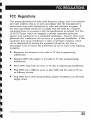
FCC REGULATIONS
FCC Regulations
This system generates and uses radio frequency energy, and if not installed
and used properly, that is, in strict accordance with the manufacturer's
instructions, may cause interference to radio and television reception. It
has been type tested and found to comply with the limits for a Class B
computing device in accordance with the specifications in Subpart H of Part
15 of FCC Rules, which are designed to provide reasonable protection
against such interference in a residential installation. However, there is no
guarantee that interference will not occur in a particular installation. ]f this
equipment does cause interference to radio or television reception, which
can be detennined by turning the eqUipment off and on, the user is
encouraged to try to correct the interference by one or more of the following
measures:
•
Reposition the antenna on the radio or TV that is experiencing
interference.
•
Relocate VMIV with respect to the radio or TV that is experiencing
interference.
•
Move VMIV away from the radio or TV that is experiencing interference.
•
Plug VMIV into a different outlet so that VMIV and the radio or TV are
on different circuits.
•
Plug VMIV into a three-prong isolation adapter (available in an electrical
supply store).
25
View-Master® Interactive Vision™ Television System
and Program Software ©1988 IDEAL. INC ..
a subsidiary of View-Master Ideal Group. Inc ..
Box 100. Portland. OR 97207
View-Master® Interactive Vision™
is based upon concepts developed by AC1V. Inc.
U.S. and Foreign Patents Pending.
View-Master® Interactive Vision™ Television System
Installing and Operating Instructions
©1988 View-Master Ideal Group. Inc.
Printed in U.S.A.
Assembled in the U.S.A. from domestic and foreign components.
Package labelled to show countries of origin.
I