1
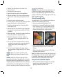
1200W 1/2”
VARIABLE SPEED
ROUTER
R1200
INSTRUCTION MANUAL
Black
Cyan
Magenta
Yellow
Code: R1200
Date: 070205
Edition: 12
Op: DCR
Contents
Warranty
Introduction
Description of symbols
Specifications
General safety instructions
Additional safety rules for electric routers
Accessories
Unpacking
Assembly
Know your product
Installing and removing collets
Installing and removing router bits
Adjusting the cutting depth
Variable speed control
Switching on and off
Making a cut
Using the parallel guide
Using the dust extraction adaptor
Using the template guide
Maintenance
Cleaning
Power cord maintenance
Repairs
2
3
3
3
4
5
6
6
6
7
8
8
8
9
9
9
10
10
11
11
11
11
11
��������������������
����������������������������������������������������
�����������������������������������������������������������
��������������������������������������������������������
���������������������������������������������������
�������������������������������������
�������������������������������������������������������
�����������������������������������������������������
������������������������������������������������������
���������������������������������������������������
��������������������������������������������������������
�����������
�������������������������������������������������������
����������������������������������������������������������
��������������������������������
��������������������������������������������������������
���������������������������������������������������
��������������������������������������������������������
��������������������������������������������������������
�����������������������������������������������
�������������������������������������������������
���������������������������������������������������������
���������������������������������������������������
����������������������������������������������������������
���������������������������������������������������������
���������������������������������������������������������
���������������������������
���������������������������������������������������
���������������������������������������������������
����������������������������������������������������
�����������������������������������������������
�������������������������������
Symbols
Introduction
The rating plate on your tool may show symbols. These
represent important information about the product or
instructions on its use.
Wear hearing protection.
Wear eye protection.
Wear breathing protection.
Your new GMC power tool will more than satisfy your
expectations. It has been manufactured under stringent
GMC Quality Standards to meet superior performance
criteria.
You will find your new tool easy and safe to operate,
and, with proper care, it will give you many years of
dependable service.
CAUTION. Carefully read through this entire Instruction
Manual before using your new GMC Power Tool. Take
special care to heed the Cautions and Warnings.
Your GMC power tool has many features that will make
your job faster and easier. Safety, performance, and
dependability have been given top priority in the
development of this tool, making it easy to maintain
and operate.
Double insulated
for additional protection.
Conforms to relevant
safety standards.
Specifications
Voltage:
Power input:
No load speed:
Collet capacity:
Environmental protection
Recycle unwanted materials instead of
disposing of them as waste. All tools, hoses
and packaging should be sorted, taken to
the local recycling centre and disposed of
in an environmentally safe way.
Plunge depth:
Insulation:
3
230–240V ~ 50Hz
1200W
8000–31500 RPM
1/4” (6.35mm)
& 1/2” (12.7mm)
50mm
Double insulated
General safety instructions
7. Dress correctly. Do not wear loose clothing or
jewellery. They can be caught in moving parts. Rubber
gloves and non-slip footwear are recommended when
working outdoors. If you have long hair, wear a
protective hair covering.
8. Use safety accessories. Safety glasses and earmuffs
should always be worn. A face or dust mask is also
required if the drilling operation creates dust.
9. Connect dust extraction equipment. If devices are
provided for the connection of dust extraction and
collection facilities, ensure that these are connected
and properly used.
10. Do not abuse the power cord. Never pull the cord to
disconnect the tool from the power point. Keep the
cord away from heat, oil and sharp edges.
11. Secure the work piece. Use clamps or a vice to hold
the work piece. It is safer than using your hand and
frees both hands to operate the tool.
12. Do not overreach. Keep your footing secure and
balanced at all times.
13. Look after your tools. Keep tools sharp and clean for
better and safer performance. Follow the instructions
regarding lubrication and accessory changes. Inspect
tool cords periodically and, if damaged, have them
repaired by an authorised service facility. Inspect
extension cords periodically and replace them if
damaged. Keep tool handles dry, clean and free from
oil and grease.
14. Disconnect idle tools. Switch off the power and
disconnect the plug from the power point before
servicing, when changing accessories and when the
tool is not in use.
15. Remove adjusting keys and wrenches. Check to see
that keys and adjusting wrenches are removed from
the tool before switching on.
16. Avoid unintentional starting. Always check that the
switch is in the OFF position before plugging in the
tool to the power supply. Do not carry a plugged in
To use this tool properly, you must observe the safety
regulations, the assembly instructions and the operating
instructions to be found in this Manual. All persons who
use and service the machine have to be acquainted with
this Manual and must be informed about its potential
hazards. Children and infirm people must not use this
tool. Children should be supervised at all times if they
are in the area in which the tool is being used. It is
also imperative that you observe the accident prevention
regulations in force in your area. The same applies for
general rules of occupational health and safety.
WARNING. When using power tools, basic safety
precautions should always be taken to reduce the risk of
fire, electric shock and personal injury. Also, please read
and heed the advice given in the additional important
safety instructions.
1. Keep the work area clean and tidy. Cluttered work
areas and benches invite accidents and injury.
2. Consider the environment in which you are working.
Do not use power tools in damp or wet locations.
Keep the work area well lit. Do not expose power tools
to rain. Do not use power tools in the presence of
flammable liquids or gases.
3. Keep visitors away from the work area. All visitors
and onlookers, especially children and infirm persons,
should be kept well away from where you are working.
Do not let others in the vicinity make contact with the
tool or extension cord.
4. Store tools safely. When not in use, tools should be
locked up out of reach.
5. Do not force the tool. The tool will do the job
better and safer working at the rate for which it was
designed.
6. Use the correct tool for the job. Do not force small
tools or attachments to do the job best handled by a
heavier duty tool. Never use a tool for a purpose for
which it was not intended.
4
tool with your finger on the switch.
17. Use outdoor rated extension cords. When a tool
is used outdoors, use only extension cords that are
intended for outdoor use and are so marked.
18. Stay alert. Watch what you are doing. Use common
sense. Do not operate a power tool when you are
tired.
19. Check for damaged parts. Before using a tool,
check that there are no damaged parts. If a part is
slightly damaged, carefully determine if it will operate
properly and perform its intended function. Check for
alignment of moving parts, binding of moving parts,
breakage of parts, proper mounting and any other
conditions that may affect the operation of the tool.
A part that is damaged should be properly repaired
or replaced by an authorised service facility, unless
otherwise indicated in this Instruction Manual.
Defective switches must be replaced by an authorised
service facility. Do not use a tool if the switch does
not turn the tool on and off correctly.
20. Guard against electric shock. Prevent body contact
with grounded objects such as water pipes, radiators,
cookers and refrigerator enclosures.
21. Use only approved parts. When servicing, use only
identical replacement parts. Use an authorised service
facility to fit replacement parts.
WARNING. The use of an accessory or attachment, other
than those recommended in this Instruction Manual, may
present a risk of personal injury.
• Ensure your mains supply voltage is the same as your
tool rating plate voltage.
• Your tool is double insulated for additional protection
against a possible electrical insulation failure within the
tool.
• Always check walls, floors and ceilings to avoid hidden
power cables and pipes.
• After long working periods external metal parts and
accessories could be hot.
• Always wear eye and ear protection and use a dust
mask.
• Handle router bits with care, they can be extremely
sharp.
• Check the bit carefully for signs of damage or
cracks before use. Replace cracked or damaged bits
immediately.
• Remove all nails, screws and other objects from the
workpiece. You can damage the bit and the tool by
cutting into a nail or other metal. It can also present a
safety hazard.
• Always use both handles and make sure that you have
a good grip on the router before proceeding with any
work.
• Keep your hands away from the rotating bit.
• Make sure that the bit is not in contact with the
workpiece when you switch the machine on.
• Before using the tool to make a cut, switch on and let
it run for a while. Watch for vibration or wobbling that
could indicate an improperly installed bit.
• Take notice of the direction of rotation of the bit and
the direction of feed.
• Do not leave the machine running unattended. Operate
the tool only when controlled by both hands.
• Always switch off and wait until the bit has come to a
complete standstill before removing the machine from
the workpiece.
Additional safety rules for electric routers
• Remove the plug from the socket before carrying out
any adjustment, servicing or maintenance.
• Fully unwind cable drum extensions to avoid potential
overheating.
• When an extension cable is required, you must ensure it
has the right ampere rating for your power tool and is
in a safe electrical condition.
5
• Reaching into the housing whilst the tool is running
and making contact with the bit.
• Kickback of workpiece and parts of workpiece.
• Bit fracture.
• Catapulting of faulty pieces from the bit.
• Do not use bits that are deformed or cracked.
• Always remove the plug from the mains socket before
making any adjustments or maintenance, including
changing the bit and setting the depth of cut.
• Do not touch the bit immediately after operation. It
may be extremely hot and could burn your skin.
• Rags, cloths, cord, string and the like should never be
left around the work area.
• Use safety equipment including safety goggles or shield,
ear protection, dust mask and protective clothing
including safety gloves.
WARNING. Before connecting a tool to a power source
(power point receptacle, outlet, etc.) be sure that the
voltage supply is the same as that specified on the
nameplate of the tool. A power source with a voltage
greater than that specified for the tool can result in
serious injury to the user, as well as damage to the tool.
If in doubt, do not plug in the tool. Using a power source
with a voltage less than the nameplate rating is harmful
to the motor.
The tool must be used only for its prescribed purpose.
Any use other than those mentioned in this Manual will
be considered a case of misuse. The user and not the
manufacturer shall be liable for any damage or injury
resulting from such cases of misuse.
The manufacturer shall not be liable for any changes
made to the tool nor for any damage resulting from such
changes.
Even when the tool is used as prescribed it is not possible
to eliminate all residual risk factors. The following hazards
may arise in connection with the tool’s construction and
design:
• Damage to hearing if effective earmuffs are not worn.
• Harmful emissions of wood dust when the machine is
used in closed rooms. Always use supplementary dust
extraction.
• Always remove the plug from the mains socket before
making any adjustments or maintenance, including
changing the bit.
• Contact with the bit.
Accessories
The GMC R1200 router is supplied with the following
accessories as standard:
• Parallel guide
• Template guide
• Wrench
• 1/2” (12.7mm) & 1/4” (6.35mm) collets
• Dust extraction adaptor
Unpacking
Due to modern mass production techniques, it is unlikely
that your GMC Power Tool is faulty or that a part is
missing. If you find anything wrong, do not operate the
tool until the parts have been replaced or the fault has
been rectified. Failure to do so could result in serious
personal injury.
Assembly
The GMC Electric Router is packed, fully assembled except
for the dust extraction adaptor and parallel guide.
6
Know your product
16
1. Left handle
2. Right handle
3. Variable speed dial
4. Depth gauge
5. Depth gauge locking knob
6. Micrometer depth adjustment
7. Depth lock lever
8. Depth turret stops
9. On/off trigger switch
10. Lock-on button
11. Spindle lock button
12. Collet nut
13. Base plate
14. Dust extraction adaptor
15. Parallel guide locking knob
16. Template guide
17. Parallel guide
18. Wrench
6
2
5
4
11
1
7
17
12
3
15
8 10
13
15
9
18
14
7
Installing and removing collets
Installing and removing router bits
CAUTION. Always ensure that the router is switched off
and unplugged from the mains supply before installing or
removing a collet.
1. The router is supplied with 2 collets, 1/2” (12.7mm)
and 1/4” (6.35mm). The 1/2” (12.7mm) collet comes
fitted to the router.
2. Depending on the size of the router bit the collet may
need to be changed to allow use of larger or smaller
diameter router bits.
3. Depress and hold the
spindle lock button (11)
to stop the spindle from
turning.
4. Whilst holding the spindle
lock button (11) loosen
the collet nut (12) by
rotating it using the wrench
provided.
5. Remove the collet nut
followed by the collet
6. Install the new collet
into the assembly; this is
sometimes easier if the
router is plunged to its full
depth.
7. Install the collet nut and
tighten by hand.
8. Firmly tighten the collet nut
by depressing and holding
the spindle lock button (11)
and then tightening the
collet nut (12) using the
wrench provided.
WARNING. Do not tighten
the collet nut without a bit in
place or you may break the
collet cone.
CAUTION. Always ensure that the router is switched off
and unplugged from the mains supply before installing or
removing a router bit.
1. Ensure the correct collet is
installed for the router bit to
be used.
2. Loosen the collet nut (12)
by depressing and holding
the spindle lock button (11)
and then rotating the collet
nut (12).
3. Insert the router bit
ensuring that the shaft of
the bit goes all the way into
the collet.
4. Tighten the collet nut
assembly by depressing
and holding the spindle
lock button (11) and then
tightening the collet nut
(12).
CAUTION. Ensure the bit is firmly secured before
commencing operation.
Adjusting the cutting depth
CAUTION. Always ensure that the router is switched off
and unplugged from the mains supply before adjusting
the depth of cut.
1. Place the machine on a flat surface and loosen the
depth gauge locking knob (5).
2. Loosen the depth lock lever
(7) and lower the machine
body until the router bit just
touches the flat surface.
3. Loosen the depth gauge
locking knob (5) and lower
the depth gauge (4) allowing
8
it to just make contact with the depth turret stop (8).
Take note of the measurement on the depth label.
4. Raise the depth gauge
and tighten using the
depth gauge locking knob
(5). The difference in
distance between the new
measurement and the
original measurement will
be equivalent to the depth
of cut. Use the micrometer
depth adjustment (6) for
precise setting of cutting
depth.
5. Loosen the depth lock lever
(7) and lower the machine
body until the depth gauge
again just makes contact with
the depth turret stop (8).
6. The depth turret stop (8)
has eight steps. By rotating
the depth turret stop it
is possible to quickly and
easily set the depth at
eight different levels. This
procedure is particularly
useful when you wish
to make a deep cut in a
number of stages.
cuts quicker and smoother at different speeds when
working in different woods or in plastic or aluminium.
2. Turn the dial to a higher number for faster speed, turn
the dial to a lower number to reduce the speed.
3. Determine the optimum speed by making a trial cut in
a scrap piece of material.
NOTE. Using the correct speed for the job increases the
life of the bit.
Switching on and off
CAUTION. Before plugging in the tool always check that
the trigger switch engages and disengages properly.
1. Press the on/off trigger switch (9) to turn on the
router.
2. To turn the router off release the on/off trigger switch.
3. If you require the router to run continually without
having to continue to apply pressure to the trigger
switch, depress the lock-on button (10) to lock the
switch on.
Variable speed control
4. The router will now run in the “locked-on” condition.
5. If the switch is in the lock-on position depress the on/
off trigger switch (9) to disengage the lock-on button
(10) and then release the switch. The router will stop.
The variable speed dial (3)
is located in the left handle
(1) for convenient speed
adjustment and improved
safety.
1. Adjust the variable speed
dial (3) to suit different
working materials. The tool
Making a cut
Your router can be used to make specialty cuts and
shapes in the surface and on the edge of wood. It
accepts a wide range of bits that are each designed for
a specific cut or shape.
9
1. Make all your adjustments as described in the
previous sections.
2. Insert and secure your router bit.
3. Adjust the height as required for the application.
4. Place the base plate (13) on the work piece ensuring
that the bit is not in contact with the material to be
cut.
5. Connect the router to the power supply.
6. Turn the router on. Ensure you have a firm grip on both
handles. Wait for the bit to attain full speed.
7. Lower the router body and lock it in position at the
desired depth of cut.
8. Move the tool over the work piece surface, keeping the
base plate flush and advancing smoothly until cutting
is complete.
9. When edge cutting, the work piece surface should be on
the left side of the bit in the feed direction.
10. Keep the cutting pressure constant, taking care
not to crowd the router causing the motor to slow
excessively.
11. On very hard woods or problem materials it may be
necessary to make more than one pass at progressive
cutting depths until the desired depth of cut is
achieved.
12. To turn the router off release the trigger switch or
press and release the trigger switch if in the “lock-on”
position.
CAUTION. Always use two hands to hold the router.
CAUTION. Where possible, clamp the work piece to the
bench.
CAUTION. Moving the machine too fast may cause a
poor quality of cut and can damage the bit or the motor.
Moving the machine too slowly may burn or mar the cut.
The proper feed rate will depend on the bit size, the type
of material being cut and the depth of the cut. Practice
first on a scrap piece of material to gauge the correct feed
rate and the cut dimensions.
WARNING. When using this router to cut flat panels such
as kitchen work surfaces, before joining please ensure
that you use an appropriate jig together with the correct
guide bush. DO NOT use the curved part of the router base
against a simple guide piece.
Using the parallel guide
The parallel guide (17) is an effective aid to cutting in a
straight line when chamfering or grooving.
1. Loosen the parallel guide locking knobs (15)
2. Feed the bars on the parallel guide through the holes
in the router base (13) on the right hand side of the
router in the feed direction. This will assist in keeping
the guide flush with the side of the work piece.
3. Adjust the distance between the router bit and parallel
guide by moving the guide until it is at the correct
distance.
4. Tighten the parallel guide locking knobs (15) to hold
the parallel guide in position.
Note. If the distance between the side of the work piece and
the cutting position is too wide, or the side of the work piece
is not straight, firmly clamp a straight board to the work
piece and use this as a guide against the router base.
Using the dust extraction adaptor
1. The dust extraction adaptor will accept most standard
vacuum cleaner nozzles allowing the dust to be
efficiently removed as the tool is used.
10
����������
���������
������
���
���������
�����
�����������
Using the template guide
Maintenance
The template guide can be
used in various ways:
• Producing duplicates of
a particular design of an
original shape.
• In conjunction with a
template, producing
decorative features.
• Repetitive cutting shapes.
If you wish to make your own templates it is best to use
a hardwood such as plywood. Use a piece that is just
thicker than the depth of the template guide. Allow for
the thickness of the guide in your template to ensure that
the work piece is cut to the correct size.
1. To attach the template
guide (16) turn the router
upside down and remove
the two fixing screws in the
centre of the router base.
2. Insert the template guide
into the base of the router
and secure using the two
fixing screws.
WARNING. Always ensure that the tool is switched off and
the plug is removed from the power point before making
any adjustments or maintenance procedures. Always wear
sturdy gloves when handling or changing bits as they can
be very sharp.
Cleaning
1. Keep the tool’s air vents unclogged and clean at all
times.
2. Remove dust and dirt regularly. Cleaning is best done
with a rag.
3. Re-lubricate all moving parts at regular intervals.
4. Never use caustic agents to clean plastic parts.
CAUTION. Do not use cleaning agents to clean the plastic
parts of the router. A mild detergent on a damp cloth is
recommended. Water must never come into contact with
the router.
Power cord maintenance
If the supply cord needs replacing, the task must be carried
out by the manufacturer, the manufacturer’s agent, or an
authorised service centre in order to avoid a safety hazard.
Repairs
Only an authorised service centre should replace the
cordset or effect other repairs.
11
GMC customer assist
If your product needs repairing, replacing,
technical service or you simply need help or advice,
please contact us on our Customer Assist Line
1300 880 001 (Australia) or 0800 445 721 (New Zealand).
For prompt service we suggest you log your service request
online at www.gmcservice.com.au. Should you not have
access to the Internet, please contact our service department
on 1300 880 001 (Australia) or 0800 445 721 (New Zealand).
7am – 7pm, 7days a week (AEST).
Please note that if repair or replacement is required,
you must provide a valid original purchase receipt.
You will need the following details at hand to log your service request;
Personal details: First & Last name, address, pick up address,
contact phone numbers, email address
Product details: Product number, date of purchase, retailer bought from,
State & postcode, receipt number, reason for the request,
copy of official purchase receipt
Attach your purchase receipt and save with this Manual for future reference.
Please refer to our website www.gmcompany.com for full GMC warranty Terms and Conditions.