1
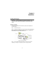
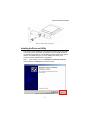
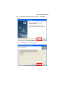
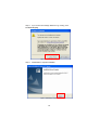
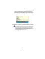
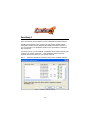
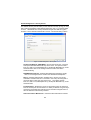
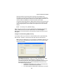
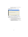
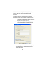
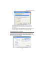
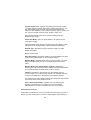
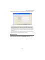
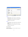
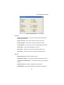
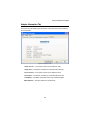
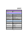
Super G Wireless PCI Adapter
Super G Wireless PCI Adapter
GN-WP01GT
User’s Guide
October 2004 - Revision 1.0
1
Contents
Chapter 1
Introduction ......................... 5
Overview ........................................................................... 5
Key Features..................................................................... 5
Package Contents ............................................................ 6
Operating Modes .............................................................. 6
LED .................................................................................... 7
System Requirements...................................................... 7
Chapter 2 Installation ............................. 8
Installing PCI Adapter ...................................................... 8
Hardware Installation ....................................................... 8
Installing the Driver and Utility........................................ 9
SmartSetup 3 .................................................................. 14
Chapter 3 Configuration ...................... 17
Using the GIGABYTE Wireless Utility........................... 17
Current Status Tab ......................................................... 17
Site Survey Tab............................................................... 21
Profile Management Tab ................................................ 22
Diagnostics Tab.............................................................. 35
Advanced Statistics ....................................................... 36
Adapter Information Tab ................................................ 39
Appendix A FAQ...................................... 40
Appendix B Wireless Security ............... 41
Super G Wireless PCI Adapter
Appendix C Troubleshooting................. 42
Appendix D Glossary.............................. 43
Appendix E Specifications ..................... 46
Appendix F Regulatory Information ...... 48
Appendix G Warranty ............................. 50
3
Federal Communication Commission Interference Statement:
This equipment has been tested and found to comply with the limits for
a Class B digital device, pursuant to Part 15 of the FCC Rules. These
limits are designed to provide reasonable protection against harmful
interference in a residential installation. This equipment generates,
uses and can radiate radio frequency energy and, if not installed and
used in accordance with the instructions, may cause harmful
interference to radio communications. However, there is no guarantee
that interference will not occur in a particular installation. If this
equipment does cause harmful interference to radio or television
reception, which can be determined by turning the equipment off and
on, the user is encouraged to try to correct the interference by one of
the following measures:
• Reorient or relocate the receiving antenna.
• Increase the separation between the equipment and receiver.
• Connect the equipment into an outlet on a circuit different from
that to which the receiver is connected.
• Consult the dealer or an experienced radio/TV technician for
help.
FCC Caution:
To assure continued compliance, any changes or modifications not
expressly approved by the party responsible for compliance could void
the user's authority to operate this equipment.
This device complies with Part 15 of the FCC Rules. Operation is
subject to the following two conditions: (1) This device may not cause
harmful interference, and (2) this device must accept any interference
received, including interference that may cause undesired operation.
IMPORTANT NOTE
FCC Radiation Exposure Statement:
This equipment complies with FCC radiation exposure limits set forth
for an uncontrolled environment. End users must follow the specific
operating instructions for satisfying RF exposure compliance.
This transmitter must not be co-located or operating in conjunction with
any other antenna or transmitter.
4
Super G Wireless PCI Adapter
Chapter 1
Introduction
Overview
The GIGABYTE WP01GT Super G PCI Adapter with SmartSetup 3 delivers to
you with today’s fastest available wireless connection.
The WP01GT Super G Wireless Adapter communicates over the 2.4GHz
802.11g wireless standard with throughput up to 15 times faster than the
11Mbps 802.11b while still remaining fully backward compatible with that
standard.
Desktops PC’s equipped with wireless adapters communicate with Wi-Fi
Application Points and wireless routers giving you the freedom from having to
run Ethernet cabling. The WP01GT has powerful security features and
lightening fast speed, moving files, watching streaming video and downloading
MP3’s faster than ever.
The WP01GT supports 64/128/152-bit WEP encryption, 802.1x RADIUS
authentication and WPA support, giving you complete peace of mind over data
security.
With SmartSetup 3 built-in setting up and configuring a secure wireless network
has never been easier. SmartSetup 3 takes all the guesswork and mystery
away, giving you a bullet-proof WPA connection generally in less than two
minutes. No pushing buttons, no fussing with technical support – three steps
and you’re done.
Get ready to join the wireless revolution, made easy by GIGABYTE.
Key Features
¾
Connects to any 802.11b, and 802.11g wireless network
¾
Data rates up to 108Mbps in Super G mode
¾
Dynamic rate shifting ensures fastest possible connection
¾
64/128/152-bit WEP encryption, 802.1x and WPA/ WPA2/ WMM
support
¾
External antenna with reversible SMA
*Theoretical throughput based on doubling of the 54Mbps radio channel.
5
Package Contents
•
•
•
•
•
GN-WP01GT Super G Wireless PCI Adapter with antenna
User Guide on CD-ROM
GN-WP01GT Quick Start Guide
Smartsetup3 Quick Start Guide (Only work with GIGABYTE Router)
Low profile bracket
If there are any missing or damaged parts, please contact your local distributor
or dealer immediately.
Operating Modes
The GN-WP01GT PCI Adapter can operate in three modes:
•
802.11b (11b) – 2.4GHz 11Mbs. This radio has a range of about 50
meters and a maximum throughput of 11 Mbit/s. Although it’s slower
than 11g, it’s still the most commonly used network today.
•
802.11g (11g) – 2.4GHz 54Mbps. In June 2003, a third standard for
Wi-Fi was ratified: 802.11g. This version works in the 2.4 GHz band
(like 802.11b) but operates at 54 Mbit/s raw, throughput like 802.11a.
It is fully backwards compatible with 11b and uses the same
frequencies.
•
Super G - The Super G is a set of technologies was invented by the
Atheros Company to double the throughput of the 54Mbps promised
by the IEEE 802.11g wireless standard. To use Super G, not only
your PCI Adapter but your wireless Router or AP must also support
the Atheros Super G functionality.
These and other advanced configuration options are explained further in
Chapter 3 - Configuring the WP01GT.
6
Super G Wireless PCI Adapter
LED
The WP01GT has one LED on the bracket next to the external antenna. The
LED is the Receive/Transmit indicator. Please see Figure 1 below.
LED Activities
Definition
Steady blink
Random blink
Looking for network association
Associated with network. Blinking increases
with activity on network
No Power
Power save mode
OFF
Slow blink
Figure 1 – Adapter LED
System Requirements
For trouble free installation and operation, please assure your PC meets the
following minimum system requirements:
•
•
•
Desktop PC with a Pentium 300Mhz or higher compatible processor
with an available PCI slot.
A CD-ROM drive
20 Mbytes of hard disk space
7
Chapter 2
Installation
Installing PCI Adapter
This chapter covers the installation of the WP01GT Adapter for your
desktop PC. The following sections will assist you with proper installation
of the PCI Adapter, and also with installing the necessary drivers and
utilities.
Hardware Installation
You will need a Phillips head screwdriver to perform the installation as
described below:
Step 1: Power OFF your PC.
Step 2: Plug the PCI Adapter into an open PCI slot on the motherboard by
pressing the card gently until the card edge connector is completely and
firmly inserted into your motherboards PCI slot.
Figure 2. Insert your PCI Adapter
Step 3: Once inserted, attaché the antenna on the mount of the PCI
Adapter by screwing it on clockwise as shown in the figure below.
8
Super G Wireless PCI Adapter
Figure 3. Attach the high gain antenna
Installing the Driver and Utility
This section covers installation of the WP01GT wireless drivers and utility.
You should use the drivers that are included on the CD-ROM rather than
the default Windows drivers. The GIGABYTE WMAG drivers have special
features and utilities that give you more stability and security than
Window’s default “Wireless Zero Configuration”.
Step 1: Upon starting your PC, the Windows Found New Hardware
wizard will open. Click Cancel to close this window.
Figure 4. Found New Hardware Screen
9
Step 2: Insert the WP01GT Setup CD into the CD-ROM drive. The
Welcome screen will automatically open.
Step 3: From the main menu, click Install Driver & Utility.
Figure 5. WP01GT Welcome Screen
10
Super G Wireless PCI Adapter
Step 4: InstallShield will install the WP01GT drivers. Click Next to
proceed.
Figure 6. InstallShield
Step 4: Setup will detect your operating system.
Figure 7. InstallShield Detect Windows OS
11
Step 5: If you receive the message Windows Logo Testing, click
Continue Anyway
Figure 8. Windows Logo Testing
Step 6: Click Finish to complete installation.
Figure 9. InstallShield Complete
12
Super G Wireless PCI Adapter
If there is a wireless network in the vicinity, the WP01GT will
automatically associate and display the new wireless connection
in your system tray. Also note the GIGABYTE wireless utility
represented by the four green bars.
Figure 10. New Wireless Connection Icon
Congratulations. Installation of your Wireless Adapter is complete.
The GIGABYTE WP01GT default wireless settings are:
Infrastructure Mode, NO security, accepts all 2.4GHz
wireless traffic, Super G mode ON, and power save mode
= ‘normal’. To change these or other settings, please see
Configuring the WP01GT in Chapter 3.
13
SmartSetup 3
Note: The following section applies to users of GIGABYTE Wireless Routers.
GIGABYTE SmartSetup 3 is a powerful, yet user-friendly wireless network
configuration wizard specially designed for GIGABYTE wireless networks. If
you are connecting to a GIGABYTE wireless router, SmartSetup 3 will detect
this and activate.
In three easy steps, you can establish a bulletproof WPA wireless network AND
configure your Internet connection. Only GIGABYTE delivers this easy,
powerful and secure solution for your wireless network!
Step 1:
Select the GIGABYTE wireless router from the available networks.
Figure 11. SmartSetup 3 Network Selection
14
Super G Wireless PCI Adapter
Step 2:
Create a WPA Passphrase using any keyboard character. Make it
no less than 8 but no more than 63 characters in length. Anyone
wishing to gain access to your network, will first need to key-in this
Passphrase. In the example below, we used ‘I love green eggs and
ham’.
Figure 12. SmartSetup 3 Define Passphrase
Step 3:
Your GIGABYTE router’s web configuration utility will automatically
open, and detect your ISP type. Just key in the Username and
Password. Done.
Figure 13. Auto detecting your ISP type
15
Note:
If Figure 13 does not appear, please type 192.168.1.254 in the address bar of
your web browser, and click “Smart Setup” from the main menu which displays.
For more information about SmartSetup 3, please see the enclosed Quick Start
Guide.
Congratulations. Your secure WPA wireless LAN and Internet
16
Super G Wireless PCI Adapter
Chapter 3
Configuration
Using the GIGABYTE Wireless Utility
This chapter explains how to use GIGABYTE Wireless Utility to view the client
adapter’s status, and transmit and receive configuration settings. The
following topics are covered in this chapter:
Current Status - Displays the complete operation state of the WP01GT
Site Survey - Displays all visible AP’s in the immediate wireless network.
Profile Management – Create and modify connection configuration in a
“Profile”
Diagnostics - Displays details regarding network connection health, and
performance.
Information - Displays the card name, MAC ID, date and versions of the
driver.
In addition to enabling you to configure your Adapter for use in various types of
networks, GIGABYTE Wireless Utility provides tools that enable you to assess
the performance of the Adapter and other devices on the wireless network.
Current Status Tab
GIGABYTE Wireless Utility Link Information screen displays network mode,
signal strength, and link quality information about the current connection. To
view your Adapter’s status and settings, open GIGABYTE Wireless Utility. The
Current Status Tab appears (see Figure 14).
17
Figure 14. Link Status Tab
Profile Name – Network configuration (Profile) your Adapter is currently
using. Creating and modifying a profile is done from the Profile
Management Tab.
Link Status – Displays the association status of the Adapter to a network.
(Not Associated, Associated, Authenticating, Authenticated, Authentication
Failed, Authentication Failed Retrying)
Wireless Mode – The frequency and rate which your current wireless
connection is capable of transmitting or receiving packets.
Network Type – Displays the network connection type, options are Ad-hoc
and Infrastructure.
Server Based Authentication – Indicates if an 802.1X compliant RADIUS
authentication server is utilized.
IP Address – The unique Internet Protocol ID for the Adapter.
Current Channel – The wireless radio channel being used for the data
transmission.
Data Encryption – Type of encryption currently in use (if any) Ad-hoc.
Signal Strength – The length of the green bar represents relative wireless
network signal strength.
18
Super G Wireless PCI Adapter
Click Advanced if you want to view more detailed status information for your
client adapter. The Advanced Status window appears (see Figure 15).
Figure 15 – Advanced Status Window
Network Name (SSID) - The name of the network to which your client
adapter is currently associated.
Server Based Authentication - The method by which authentication to a
back-end server is being performed to establish secure connectivity.
(None, LEAP, EAP-TLS, PEAP (EAP-GTC), or PEAP (EAP-MSCHAP V2))
Data Encryption - The data encryption type that was negotiated with the
access point (in infrastructure mode) or another client (in ad hoc mode)
upon association. (None, WEP, CKIP, or TKIP)
Authentication Type - Specifies whether the client adapter must share the
same WEP keys as the access point in order to authenticate or can
authenticate to the access point regardless of its WEP settings.
(Open or Shared)
Message Integrity Check - Indicates whether your client adapter is using
message integrity check (MIC) to protect packets sent to and received from
the access point.
MIC prevents bit-flip attacks on encrypted packets. During a bit-flip attack,
an intruder intercepts an encrypted message, alters it slightly, and
retransmits it, and the receiver accepts the retransmitted message as
legitimate.
Associated AP Name - The name of the access point to which your client
adapter is associated. It is shown only if the client adapter is in
infrastructure mode.
19
Note: This field shows up to 15 characters although the name of the
access point may be longer.
Associated AP IP Address - The IP address of the access point to which
your client adapter is associated. It is shown only if the client adapter is in
infrastructure mode.
Associated AP MAC Address - The MAC address of the access point to
which your client adapter is associated. It is shown only if the client adapter
is in infrastructure mode.
Power Save Mode - The client adapter's current power consumption
setting. (CAM (Constantly Awake Mode), Max PSP (Max Power Saving), or
Fast PSP (Power Save Mode))
Current Power Level - The power level at which your client adapter is
currently transmitting. The maximum level is dependent upon the radio
band used and your country's regulatory agency.
(10, 20, 30, 50, 63, or 100 mW (802.11b/g band)
Available Power Levels - The power levels at which your client adapter
is capable of transmitting. The maximum level is dependent upon the radio
band used and your country's regulatory agency. 10, 20, 30, 50, 63, or 100
mW (802.11b/g))
Current Signal Strength - The signal strength for all received packets.
The higher the value, the stronger the signal. (0 to 100% or 0 to -100 dBm)
Current Signal Quality - The signal quality for all received packets. The
higher the value, the clearer the signal. (0 to 100%)
Current Noise Level - The level of background radio frequency energy in
the current radio band. The lower the value, the less background noise
present. (0 to -100 dBm)
Up Time - The amount of time (in hours:minutes:seconds) since the client
adapter has been receiving power. If the adapter has been running for
more than 24 hours, the time is displayed in days, hours:minutes:seconds.
802.11b Preamble - Indicates whether your client adapter is using only
long radio headers or short and long radio headers. (Short & Long or Long
Only)
Current Link Speed - The rate at which your client adapter is currently
transmitting data packets. (1, 2, 5.5, 6, 9, 11, 12, 18, 24, 36, 48, or 54
Mbps)
Channel - The channel that your client adapter is currently using for
communications. This field displays Scanning while the client adapter
20
Super G Wireless PCI Adapter
searches for a channel.
Frequency - The radio frequency that your client adapter is currently using
for communications. This field displays "Scanning" while the client adapter
searches for a frequency.
Channel Set - The regulatory domain for which your client adapter is
currently configured. This value is not user selectable. ( America, EMEA,
Japan, or Rest of World)
Click OK to close the Advanced Status window.
Site Survey Tab
The Site Survey screen displays a list of infrastructure and Ad-hoc networks
available for connection in the “Network Name” column. To connect to a
network, simply click on the network name, and press the Activate button. Note
that secure networks (represented by the key icon) will require a Passphrase.
Figure 16. Site Survey Tab
Network Name – The SSID or unique name of the wireless network.
Key Icon
- Indicates a secure or open network
Signal Strength – The strength of signal, reported in dB.
21
Channel – The channel upon which the network broadcasts.
Wireless Mode – The radio frequency which the network broadcasts.
Profile Management Tab
Every session runs under a Profile – even if it is the ‘default’ Profile.
The Profile Management Tab displays your current wireless connection profile,
and its details. You may add as many wireless profiles as you wish, by
clicking New. You may even import and export your profile as a configuration
file. This is handy if the laptop is to be used between two or more AP’s. There
are two windows in the Profile Management Tab. The top window displays all
profiles, with a green radio icon next to the active profile. The bottom window
displays a brief summary of the configuration of the selected profile. Clicking
Modify allows you to change the wireless connection configuration settings.
Figure 17. Profile Management Tab
New – Click to create a new profile.
Modify – Click to modify the selected profile.
Remove – Click to remove the selected profile
Activate – Click to activate the selected profile (and simultaneously
de-activate the current profile)
22
Super G Wireless PCI Adapter
Import – Import a profile configuration from file.
Export – Export a profile configuration to a file.
Order Profiles – Arranges the profiles in a list according to an order
which is convenient to you.
Radio
- Toggle on or off the WP01GT wireless radio receiver.
Profile Management > General Tab
Clicking Modify from the Profile Management Tab will present the Profile
Management Dialogs. There are three tabs here: General, Security, and
Advanced Tab.
Figure 18. Profile Management > General Tab
Profile Name – A user defined, free form name for the new profile.
Client Name – The Desktop PC name. This field is automatically
populated but can be edited as you wish.
Network Names – You may define up to three network names which this
profile is used when connecting.
23
Profile Management > Security Screen
The wireless security sub tab offers you the method of security (if any) you may
select. Select WPA/WPA2, WPA/WPA2-Passphrase, 802.1x, Pre Shared WEP,
or None. WPA/WPA2 is a security standard stronger than WEP encryption,
and 802.1x is the RADIUS authentication service. The default setting is None.
Figure 19. Profile Management > Security Tab
Set Security Method – WPA/WPA2 – Wi-Fi Protected Access - Choosing
WPA opens the WPA/WPA2 EAP drop-down menu. The options include
EAP-TLS, EAP-TTLS, PEAP(EAP-GTC), PEAP(EAP-MSCHAR V2), LEAP
and EAP-FAST. Click on the Configure button and fill in the Define
Certificate dialog.
WPA/WPA2-Passphrase - Enables WPA/WPA2-Pre Shared Key (PSK).
Click on the Configure button and fill in the WPA/WPA2 Passphrase.
802.1x – RADIUS Authentication. Enables 802.1x security, and is only
available if a RADIUS Server is connected to the router) Choosing 802.1x
opens the 802.1x EAP type drop-down menu. The options include
EAP-TLS, EAP-TTLS, PEAP(EAP-GTC), PEAP(EAP-MSCHAR V2), LEAP
and EAP-FAST
Pre-Shared Key - Enables the use of pre-shared keys that are defined on
both the access point and the station. To define pre-shared encryption keys,
choose the Pre-Shared Key radio button and click the Configure button to
fill in the Define Pre-Shared Keys window.
Allow Associate to Mixed Cells – Check the Allow Association to Mixed
24
Super G Wireless PCI Adapter
Cells check box if the access point to which the client adapter is to
associate (or the VLAN to which the client will be assigned) has WEP set
to Optional and static WEP is enabled on the client adapter. Otherwise, the
client is unable to establish a connection with the access point.
Uncheck the Allow Association to Mixed Cells check box if the access point
to which the client adapter is to associate (or the VLAN to which the client
will be assigned) does not have WEP set to Optional. This is the default
setting.
None – no security is set. (Default setting)
Select the type of security encryption (WPA/WPA2, WPA/WPA2-Passphrase,
WEP or RADIUS 802.1X) from the radio buttons, and click Configure.
Depending on the security selected, the following Configure Security Screens
will appear.
Configure Pre Shared Key (WEP) Security
To use WEP, select if you want Hex or ASCII method, enter a pre-shared key,
select 64-bits, 128-bits, or 152-bits from the drop down box and click OK.
Note: ASCII text WEP keys are not supported on GIGABYTE Routers, you
must choose the Hexadecimal (0-9,A-F) option if you are connecting with
these Access Points.
Figure 20. WEP key configuration
WPA/WPA2-Passphrase - When you select WPA/WPA2, the target
802.11 device must also be WPA/WPA2 enabled in order to
communicate with each other. Obtain the WPA/WPA2 Passphrase for
the access point from your system administrator and inter it in the
WPA/WPA2 Passphrase field.
•
WPA/WPA2 Passphrase must contain 8 to 63 ASCII text
characters or 64 hexadecimal characters.
•
Your client adapter's WPA/WPA2 Passphrase must match
25
the Passphrase used by the access point with which you
are planning to communicate.
Click OK to save your changes and to return to the Profile
Management window.
Figure 21. Enter WPA Passphrase
Using LEAP – Before you can enable LEAP authentication, your
network access point must be configured for LEAP authentication.
Perform one of the following from the Security Tab:
z
z
If you want to enable LEAP without WPA/WPA2, choose
802.1x under Set Security Options and LEAP in the
802.1x EAP Type drop-down box.
If you want to enable LEAP with WPA/WPA2, choose
WPA/WPA2 under Set Security Options and LEAP in the
WPA/WPA2 EAP Type drop-down box.
26
Super G Wireless PCI Adapter
Figure 22. LEAP Settings
Use Temporary User Name and Password - Requires you
to enter the LEAP username and password each time the
computer reboots in order to authenticate and gain access to
the network.
Use Saved User Name and Password - Does not require
you to enter a LEAP username and password each time the
computer reboots. Authentication occurs automatically as
needed using a saved username and password (which are
registered with the RADIUS server).
User Name – Enter a username
Password/Confirm Password – Enter a password in both
fields
Domain - If you wish to specify a domain name that will be
passed to the RADIUS server along with your username,
enter it in the Domain field.
Include Windows Logon Domain with User Name - If you
work in an environment with multiple domains and therefore
want your Windows login domain to be passed to the
RADIUS server along with your username
27
LEAP was proven to be susceptible to dictionary attacks, and
EAP-FAST is preferable to LEAP. In short, EAP-FAST is hardened
LEAP with better crypto protecting the challenge/response
mechanism.
Using EAP-FAST – Before you can enable EAP-FAST authentication,
your network access point must be configured for EAP-FAST
authentication. Perform one of the following from the Security Tab:
z
z
If you want to enable EAP-FAST without WPA/WPA2,
choose 802.1x under Set Security Options and LEAP in
the 802.1x EAP Type drop-down box.
If you want to enable EAP-FAST with WPA/WPA2,
choose WPA/WPA2 under Set Security Options and
LEAP in the WPA/WPA2 EAP Type drop-down box.
Figure 23. EAP-FAST Settings
Use Temporary User Name and Password - Requires you
to enter the EAP-FAST username and password each time
the computer reboots in order to authenticate and gain
access to the network.
28
Super G Wireless PCI Adapter
Use Saved User Name and Password - Does not require
you to enter an EAP-FAST username and password each
time the computer reboots. Authentication occurs
automatically as needed using a saved username and
password (which are registered with the RADIUS server).
User Name – Enter a username
Password/Confirm Password – Enter a password in both
fields
Domain -- If you wish to specify a domain name that will be
passed to the RADIUS server along with your username,
enter it in the Domain field.
Include Windows Logon Domain with User Name -- If you
work in an environment with multiple domains and therefore
want your Windows login domain to be passed to the
RADIUS server along with your username
Select the protected access credential (PAC) authority
provisioning
z
Check the Allow Automatic PAC Provisioning for
this Profile checkbox to have the system
automatically provide the PAC for this profile.
z
OR. To set a PAC authority, choose a PAC Authority
from the drop-down list to use. Click the Select More
button to import or delete a new PAC authority
Using EAP-TLS, EAP-TTLS or PEAP
Before you can enable EAP-TLS, EAP-TTLS or PEAP authentication,
our network devices must meet the following requirements:
•
You must have a valid Windows username and password,
and the password cannot be blank.
•
The appropriate certificates must be installed on your
computer. EAP-TLS requires both a Certificate Authority
(CA) certificate and a user certificate while EAP-TTLS or
PEAP requires only a CA certificate.
If you want to enable EAP-TLS without WPA/WPA2, choose
802.1x under Set Security Options and EAP-TLS in the 802.1x EAP
Type drop-down box. If you want to enable EAP-TLS with
WPA/WPA2, choose WPA/WPA2 under Set Security Options and
EAP-TLS in the WPA/WPA2 EAP Type drop-down box.
29
Figure 24 - Define Certificate Window
Select a Certificate – Choose a certificate from the dropdown list.
Trusted Root Certification Authorities – Choose an authority from
the dropdown list.
Server/Domain Name - Leave the Server/Domain Name field blank to
allow the client to accept a certificate from any server that supplies a
certificate signed by the certificate authority listed in the Server
Properties drop-down list.
Login Name - If the Login Name field is not filled in automatically,
enter your username in this format: [email protected]
Enabling EAP-TTLS
If you want to enable EAP-TTLS without WPA/WPA2, choose 802.1x under
Set Security Options and EAP-TTLS in the 802.1x EAP Type drop-down box.
If you want to enable EAP-TTLS with WPA/WPA2, choose WPA/WPA2 under
Set Security Options and EAP-TTLS in the WPA/WPA2 EAP Type drop-down
box.
30
Super G Wireless PCI Adapter
Figure 25 - Define EAP-TTLS Certificate Window
Trusted Root certification Authorities – Choose the certificate
authority from which the server certificate was downloaded in the
drop-down list.
User information for EAP-TTLS Authentication - Enter your
EAP-TTLS username and password in the corresponding fields.
Enabling PEAP (EAP-GTC)
If you want to enable PEAP (EAP-GTC) without WPA/WPA2, choose 802.1x
under Set Security Options and PEAP (EAP-GTC) in the 802.1x EAP Type
drop-down box.
If you want to enable PEAP (EAP-GTC) with WPA/WPA2, choose WPA/WPA2
under Set Security Options and PEAP (EAP-GTC) in the WPA/WPA2 EAP Type
drop-down box.
31
Figure 26 - Define PEAP Certificate Window
Trusted Root Certification Authorities – Choose the certificate
authority from which the server certificate was downloaded in the
drop-down list.
Set Password – Select Token or Static Password, depending on your
users database.
User information for PEAP (GTC) Authentication - Enter your PEAP
username and password in the corresponding fields.
Enabling PEAP (EAP MSCHAP V2)
If you want to enable PEAP (EAP-MSCHAP V2) without
WPA/WPA2, choose 802.1x under Set Security Options and PEAP
(EAP-MSCHAP V2) in the 802.1x EAP Type drop-down box.
If you want to enable PEAP (EAP-MSCHAP V2) with WPA/WPA2,
choose WPA/WPA2 under Set Security Options and PEAP
(EAP-MSCHAP V2) in the WPA/WPA2 EAP Type drop-down box.
32
Super G Wireless PCI Adapter
Figure 27 - Define EAP Server Window
Trusted Root Certification Authorities – Choose the certificate
authority from which the server certificate was downloaded in the
drop-down list.
User information for PEAP (EAP-MSCHAP V2) Authentication - Enter
your PEAP username and password in the corresponding fields.
Profile Management > Advanced Screen
The Profile Management (Advanced) window (see Figure 28) enables you to
set parameters that control how the client adapter operates within an
infrastructure or ad hoc network. To open this window, click the Advanced tab
from any Profile Management window.
Figure 28 – Advanced Profile Management
33
Transmit Power Level - Specifies the preferred power level at which
your client adapter transmits. Although the adapter supports up to 100
mW, the transmit power level that is actually used is limited to the
maximum value allowed by your country's regulatory agency (FCC in the
U.S., DOC in Canada, ETSI in Europe, TELEC in Japan, etc.).
Reducing the transmit power level conserves battery power but
decreases radio range.
Power Save Mode - Sets your client adapter to its optimum power
consumption setting.
CAM (Constantly Awake Mode), Fast PSP (Power Save Mode), or Max
PSP (Max Power Saving) Default: CAM (Constantly Awake Mode)
Network Type - Specifies the type of network in which your client
adapter is installed.
Default: Infrastructure
802.11b Preamble - Determines whether your client adapter uses both
short and long radio headers or only long radio headers.
Wireless Mode - Specifies the frequency and rate at which your client
adapter should transmit packets to or receive packets from access
points.
Wireless Mode when starting Ad hoc network - Specifies the
frequency and rate at which your client adapter should transmit packets
to or receive packets from other clients (in ad hoc mode).
Channel - Specifies the channel that your client adapter uses for
communications in a 2.4-GHz ad hoc network. The available channels
conform to the IEEE 802.11 Standard for your regulatory domain.
The channel of the client adapter must be set to match the channel used
by the other clients in the wireless network.
802.11 Authentication Mode - Specifies how your client adapter
attempts to authenticate to an access point. Open and shared
authentication do not rely on a RADIUS server on your network.
Preferred Access Points
If this profile is configured for use in an infrastructure network and you want to
specify up to four access points to which the client adapter should attempt to
34
Super G Wireless PCI Adapter
associate, click Preferred APs. The Preferred Access Points window appears
Figure 29 – Specify MAC Access Points
Leave the Access Point 1 through Access Point 4 fields blank or enter the
MAC addresses of up to four preferred access points to which the client
adapter can associate; then click OK. (The MAC address should consist of
12 hexadecimal characters.) If the specified access points are not found or
the client adapter roams out of range, the adapter may associate to another
access point.
Go to the next section to set additional parameters or click OK to save your
changes and return to the Profile Management window.
Diagnostics Tab
Basic transmit and receive statistics are available here (Figure 30), with more
advanced statistics available from the Advanced Statistics button.
35
Figure 30 – Diagnostics Tab
Transmit:
Multicast Packets – Number of packets sent to a multicast address
Broadcast Packets – Number of packets sent to a broadcast address
Unicast Packets – Number of packets sent to a unicast address
Total Bytes – Total bytes transmitted
Receive:
Multicast Packets – Number of packets received as a multicast address
Broadcast Packets – Number of packets received as a broadcast
address
Unicast Packets – Number of packets received as a unicast address
Total Bytes – Total bytes received
Advanced Statistics
More advanced statistics about your network are available in the Advanced
Statistics window (Figure 31).
36
Super G Wireless PCI Adapter
Figure 31. Advanced Statistics
Transmit
Frames Transmitted OK – The number of total frames transmitted or
received without errors.
Frames received – The number of frames receive by the client.
Frames Dropped – The number of frames dropped by the client.
No ACK Frames – Frames which were not acknowledged by the client.
ACK Frames – Frames acknowledged by the client.
RTS Frames – Request to Send, Client sends RTS frame to AP.
CTS Frames – Clear to Send. Client receives CTS frame from AP.
Receive
Beacons Received – Beacon packets received.
Frames Received OK – The number of frames received without errors.
Frames Received with Errors – The number of frames not received due
to errors.
Duplicate Frames – Number of duplicate frames received
AP Mismatches – MAC address/public key combination mismatches.
37
Sometimes indicative of hacking/spoofing.
Data Rate Mismatches - The number of times the client adapter tried to
associate to an access point but was unable to because the adapter's
data rate was not supported by the access point.
Authentication Time-Out - The number of times the client adapter tried
to authenticate to an access point but was unable to because the access
point did not respond fast enough (timed out).
Authentication Rejects - The number of times the client adapter tried to
authenticate to an access point but was rejected.
Association Time-Out - The number of times the client adapter tried to
associate to an access point but was unable to because the access point
did not respond fast enough (timed out).
Association Rejects - The number of times the client adapter tried to
associate to an access point but was rejected.
Standard MIC OK - The number of frames that were received with the
correct message integrity check (MIC) value.
Standard MIC Errors - The number of frames that were discarded due to
an incorrect message integrity check (MIC) value.
CKIP MIC OK - The number of frames that were received with the correct
message integrity check (MIC) value when CKIP was being used.
CKIP MIC Errors - The number of frames that were discarded due to an
incorrect message integrity check (MIC) value when CKIP was being
used.
38
Super G Wireless PCI Adapter
Adapter Information Tab
The Driver Info Tab displays the information of the card’s driver, MAC address
and version date.
Figure 31. Adapter Info Tab
Utility Version -- The version number of the WP01GT utility.
Utility Date -- The date of manufacture of the WP01GT utility file.
Driver Version – The version number of the WP01GT driver.
Driver Date – The date of manufacture of the WP01GT driver file.
Card Name – The Make and Model name of the wireless Adapter.
MAC Address – The MAC address of the WP01GT.
39
Appendix A
FAQ
This section provides solutions to common problems that may occur during
installation, configuration or use of the Adapter.
Q:
A:
What is Ad-hoc mode?
When a wireless network is set to Ad-hoc mode, the wireless-equipped
computers are configured to communicate directly with each other. The
Ad-hoc wireless network will not communicate with any wired network..
Q:
A:
What is Infrastructure mode?
Also referred to as Access Point Mode. When a wireless network is set to
infrastructure mode, the wireless network is configured to communicate
with a wired network through a wireless access point.
Q:
A:
What is the IEEE 802.11g standard?
The IEEE 802.11g standard specifies data rates of up to 54 Mbps in the
2.4-GHz band. It uses Orthogonal Frequency Division Multiplexing
(OFDM), which is provided by this standard and is compatible with
802.11b standard offering speeds of about 11 Mbps. This standard uses
Complementary Code Keying (CCK) modulation. Both 11g and 11b can
operate at a range of up to 300 feet.
40
Super G Wireless PCI Adapter
Appendix B
Wireless Security
The WP01GT, and all of GIGABYTE’s wireless offerings are all built to deliver
the easiest and most secure wireless networking experience as possible.
Please understand the following key points in order to enjoy a safe and secure
wireless network.
Wireless Security Tips
The following are basic wireless security tips which will minimize the chance of
a breach in your private wireless network:
1. Change the default SSID.
2. Disable SSID Broadcast.
3. Change the default password for the Administrator account.
4. Enable MAC Address Filtering.
5. Change the SSID periodically.
6. Use the highest encryption algorithm possible. Use WPA if it is available.
7. Change the WEP encryption keys periodically.
Don’t Be a Statistic
Wireless networks are easy to find. Statistics show that roughly half of all
wireless networks have no security in place at all, i.e. they are open systems for
anyone to freely use as they please. In fact, nearly 25% of the time, the
default administrator username/password remain as system defaults! Leaving
your wireless network open for the taking. Following the easy steps outlined
above will give you peace of mind, and keep your network out of reach from
would be hackers. Don’t be a statistic!
41
Appendix C
Troubleshooting
Problem 1:
The WP01GT does not work correctly.
Response :
•
•
•
Problem 2:
Try removing and re-inserting the Adapter. Make sure that
the WP01GT is FIRMLY seated into the PCI slot.
Uninstall the driver software from your PC, and try
reinstalling.
Try rebooting your PC.
I cannot communicate with other computers in Access
Point (infrastructure) Mode.
Response:
•
•
Assure that the Desktop PC is powered on.
Assure that the WP01GT is configured with the same SSID
and WEP settings as other computers in the Access Point
configuration.
42
Super G Wireless PCI Adapter
Appendix D
Glossary
ADSL
Asymmetric digital subscriber line (ADSL) is a new modem technology that
converts existing twisted-pair telephone lines into access paths for high-speed
communication of various sorts.
Auto-MDI/MDIX
On a network hub or switch, an auto-MDI/MDIX port automatically senses if it
needs to act as a MDI or MDIX port. The auto- MDI/MDIX capability eliminates
the need for crossover cables.
Auto-negotiate
To automatically determine the correct setting. The term is often used with
communications and networking
DHCP
The Dynamic Host Configuration Protocol (DHCP) is an Internet protocol for
automating the configuration of computers that use TCP/IP. DHCP can be used
to automatically assign IP addresses, to deliver TCP/IP stack configuration
parameters such as the subnet mask and default router, and to provide other
configuration information such as the addresses for printer, time and news
servers.
DMZ
In computer networks, a DMZ (demilitarized zone) is a computer host or small
network inserted as a "neutral zone" between a company's private network and
the outside public network. It prevents outside users from getting direct access
to a server that stores company data. Typically, the DMZ contains devices
accessible to Internet traffic, such as Web (HTTP) servers, FTP servers, SMTP
(e-mail) servers and DNS servers.
DNS
The Domain Name System (DNS) is a distributed Internet directory service.
DNS is used mostly to translate between domain names and IP addresses, and
to control Internet email delivery. Most Internet services rely on DNS to work. If
DNS fails, web sites cannot be located and email delivery service will be
suspended.
Dynamic IP Address
An IP address is automatically assigned to a user’s AP in a TCP/IP network
typically by a DHCP server.
43
Firewall
A system designed to prevent unauthorized access to or from a private network.
Firewalls can be implemented in both hardware and software, or a combination
of both. Firewalls are frequently used to prevent unauthorized Internet users
from accessing private networks connected to the Internet, especially intranets.
All messages entering or leaving the intranet pass through the firewall, which
examines each message and blocks those that do not meet the specified
security criteria.
Gateway
A device, usually a Router, that connects hosts on a local network to other
networks.
IP Address
Every PC on the Internet has a unique identifying number, called an IP Address.
A typical IP address looks like this: 216.27.61.137
IPSec
IPSec stands for IP Security. It provides authentication and encryption over the
Internet. It functions at Layer 3 and thus secures everything on the network. It
has become a standard protocol used for virtual private networks (VPNs).
MAC Address
On a local area network (LAN) or other network, the MAC (Media Access
Control) address is your computer's unique hardware number. Usually written
as: 01:23:45:67:89:ab
MTU
The size in bytes of the largest packet that can be sent or received.
NAT
A technique by which several hosts share a single IP address for accessing to
the Internet.
Ping (Packet Internet Groper)
A utility to determine whether a specific IP address is accessible. It works by
sending a packet to the specified address and waiting for a reply. PING is used
primarily to troubleshoot Internet connections.
SSID
SSID is the name representing the Router in WLAN.
44
Super G Wireless PCI Adapter
PPPoE
Point-to-Point over Ethernet is a protocol for connecting remote hosts to the
Internet over an always-on connection by simulating a dial-up connection.
Router
A device that forwards data packets along networks. A router is connected to at
least two networks, commonly two LANs or WANs or a LAN and its ISP
network. Routers are located at gateways, the places where two or more
networks connect.
Subnet Mask
A mask used to determine which subnet an IP address belongs to. An IP
address has two components, the network address and the host address.
Subnetting enables the network administrator to further divide the host part of
the address into two or more subnets.
TCP/IP
TCP/IP (Transmission Control Protocol/Internet Protocol), the suite of
communications protocols used to connect hosts on the Internet.
VPN
Virtual private networks are secured private network connections, built on top of
publicly accessible infrastructure, such as the Internet or the public telephone
network. VPNs typically employ some combination of encryption, digital
certificates, strong user authentication and access control to provide security to
the traffic they carry. They usually provide connectivity to many machines
behind a gateway or firewall.
WAN
Wide Area Network, a communication network that covers a relatively broad
geographic area, consisting of two or more LANs. Broadband communication
over the WAN is often through public networks such as the ADSL or Cable
systems, or through leased lines or satellites. To simplify it, please image
network as a WAN.
WEP
WEP (Wired Equivalent Privacy) is a data privacy mechanism based on a
64/128-bit shared key algorithm, as described in the IEEE 802.11 standard.
45
Appendix E
Specifications
1. System
Host Interface
PCI
2.3
Operating Voltage
3.3VDC ± 5%
2. RF Performance
802.11b
Frequency Band
2412 ~ 2484 MHz (subject to local regulation)
Modulation Technology
DSSS (Direct Sequence Spread Spectrum)
Modulation Techniques
CCK, DQPSK, DBPSK
Date Rates
11, 5.5, 2, 1Mbps, auto fallback
Typical Power Consumption
Doze: 25mA
Receive: 250mA
Transmit: 560mA
Peak Output Power
21dBm @ Nominal Temp Range
Minimum Receive Sensitivity
-85dBm @ 11 Mbps, Nominal Temp Range
Antenna
External antenna with the gain of 2dBi, L type
802.11g(backward compatible to 802.11b)
Frequency Bands
2412-2484 MHz (subject to local regulations)
Modulation Technology
OFDM and DSSS
Modulation Techniques
Date Rates
Typical Power Consumption
Peak Output Power
Receive sensitivity
Antenna
64QAM, 16QAM, QPSK, BPSK, CCK, DQPSK,
DBPSK
Base mode: 54, 48, 36, 24, 18,12, 9, 11, 6, 5.5, 2,
and 1 Mbps, auto fallback
Turbo mode: 108, 96, 72, 48, 36, 24, 18 and 12
Mbps auto fallback
Doze: 25mA
Receive: 250 mA
Transmit: 530 mA
20dBm @ Nominal Temp Range
Minimum -72dBm; typical -74dBm @54Mbps,
Nominal Temp Range
External antenna with the gain of 2dBi, L type
46
Super G Wireless PCI Adapter
3.Safety Regulation and Operating Environment
EMC certification
FCC Part 15 (USA)
DGT (Taiwan)
CE (Europe)
Temperature Range
Operating: 0 ~ 55 deg C, Storing: -20 ~ 65 deg C
Humidity
Max. 90% Non-condensing
4. Software Support
Driver
Security
Windows 2000/XP
WPA; AES; 802.1X client for Windows XP;
64/128/152 bit WEP
Roaming
Seamless roaming among 802.11b/g access points.
Management Utility
Monitors the network situation.
5. Mechanical
Dimensions
120mm*121mm*20mm (120mm*81mm*20mm)
Weight
52.5(48.5)± 1 g
Packaging
Packaging specially used by Gigabyte.
* Subject to Change without Notices
47
Appendix F
Regulatory Information
CE Mark Warning: This is a Class B product. In a domestic environment, this product may cause
radio interference, in which case the user may be required to take adequate measures.
FCC Statement: This equipment has been tested and found to comply with the limits for a Class B
digital device, pursuant to Part 15 of the FCC Rules. These limits are designed to provide reasonable
protection against harmful interference in a residential installation. This equipment generates, uses
and can radiate radio frequency energy and, if not installed and used in accordance with the
instructions, may cause harmful interference to radio communications. However, there is no guarantee
that interference will not occur in a particular installation. If this equipment does cause harmful
interference to radio or television reception, which can be determined by turning the equipment off and
on, the user is encouraged to try to correct the interference by one of the following measures:
•
•
•
•
Reorient or relocate the receiving antenna.
Increase the separation between the equipment and receiver.
Connect the equipment into an outlet on a circuit different from that to which the receiver is
connected.
Consult the dealer or an experienced radio/TV technician for help.
FCC Caution: To assure continued compliance, any changes or modifications not expressly approved
by the party responsible for compliance could void the user authority to operate this equipment.
This device complies with Part 15 of the FCC Rules. Operation is subject to the following two
conditions: (1) This device may not cause harmful interference, and (2) this device must accept any
interference received, including interference that may cause undesired operation.
IMPORTANT NOTE:
FCC Radiation Exposure Statement:
This equipment complies with FCC radiation exposure limits set forth for an uncontrolled environment.
This equipment should be installed and operated with minimum distance 20cm between the radiator &
your body. The antenna(s) used for this transmitter must not be co-located or operating in conjunction
with any other antenna or transmitter.
Europe - Declaration of Conformity
This device is a 2.4 GHz low power RF device intended for home and office use in
EU and EFTA member states. In some EU / EFTA member states some restrictions
may apply. Please contact local spectrum management authorities for further
details before putting this device into operation.
GIGA-BYTE Technology, Inc. declares that the product: Wireless Broadband Router Model Number:
GN-B49G is in conformity with and in accordance with the European Directive of EMC, 89/336 EEC
for the following sections:
EN 61000-3-2, EN 61000-3-3, EN 55024, and EN 55022 Disturbances and Immunities
GIGA-BYTE Technology, Inc. also declares the conformity of above mentioned product with the actual
required safety standards in accordance with LVD Directive 73/23 EEC:
EN 60950 Safety
In accordance with R&TTE Directive 1995/5/EC, Part 17: Requirements for Operation in the European
Community, GIGA-BYTE Technology, Inc declares the conformity of the above mentioned products
for:
48
Super G Wireless PCI Adapter
EN 300 328-2 V1.2.1, ETSI EN 300 328-1:V1.3.1, EN 301 489-1, and EN 301 489-17 Technical
Requirements for Radio Equipment
Countries of Operation and Conditions of Use in the European Community
The user should run the configuration utility program provided with this product to check the current
channel of operation and confirm that the device is operating in conformance with the spectrum usage
rules for European Community countries as described in this section. European standards dictate a
maximum radiated transmit power of 100mW EIRP and a frequency range of 2.400 - 2.4835 Ghz.
Trademarks: GIGABYTE is a registered trademark of GIGA-BYTE Technology, Inc. Other
trademarks or registered trademarks are the property of their respective manufacturers or owners.
Copyright Statement: No part of this publication or documentation accompanying this Product may
be reproduced in any form or by any means or used to make any derivative such as translation,
transformation, or adaptation without permission from GIGABYTE/GIGA-BYTE Technology, Inc., as
stipulated by the United States Copyright Act of 1976. Contents are subject to change without prior
notice. Copyright© 2004 by GIGA-BYTE Technology, Inc. All rights reserved.
49
Appendix G
Warranty
Limited Warranty Statement (1-Year Warranty)
Thank you for purchasing the GIGABYTE Product. This limited warranty statement will provide you
one year warranty starting from the purchase date. Of which if any defect is occurred due to accidents
or any man-made factors, or any unauthorized torn-off or damage to GIGABYTE’s sticker on the
product, GIGABYTE Technology will not provide after-sale services, such as:
•
•
•
•
•
•
•
•
Products are damaged due to any violation of instructions on user manual.
Hardware is damaged due to inappropriate assembling.
Products are damaged due to the use of illegal accessory.
Products are damaged due to parts disassembling without authorization.
Products are damaged due to exceeding environment limits.
Products are damaged due to unexpected external force.
Products are damaged due to nature disasters.
Products are copies or illegally smuggled goods.
PLEASE RECORD THE FOLLOWING INFORMATION REGARDING
YOUR WARRANTY
Name of Customer:
Phone No:
Address:
Email:
Model:
Serial:
Date of Purchase:
Place of Purchase:
From Whom:
Distributor:
Customer Service
GIGA-BYTE TECHNOLOGY CO., LTD.
No.6, Bau Chiang Road, Hsin-Tien,
Taipei Hsien, Taiwan
Toll Free 0800-079-666
Tel: 886-2-8665-2665 Fax:886-2-89124007
http://www.gigabyte.com.tw
50