1
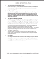
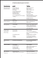
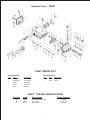
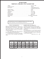
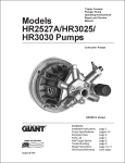
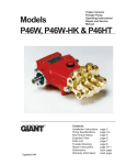
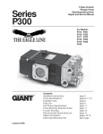
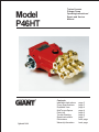
Model P46HT Updated 3/98 Triplex Ceramic Plunger Pump Operating Instructions/ Repair and Service Manual Contents: Installation Instructions: Pump Specifications: Exploded View: Kits/Torque Specs: Parts List: Trouble Shooting: Repair Instructions: Dimensions: Warranty Information: page 2 page 3 page 4 page 4 page 5 page 6 page 7 back page back page REPAIR INSTRUCTIONS - P46HT 1. To Check Suction and Discharge Valves Loosen valve plugs (41 and 43) using a socket wrench. Note the arrangement for reassembly and check the discharge valves underneath and suction valves (in suction valve adapter 39). 2. To Check V-Sleeves Separate valve casing (29) from the crankcase (1) and pull off over the plungers. If the seals have to be replaced, remove all parts from the valve casing (29) in the suction valve direction. Grease new v-sleeves (31) with grease before installing. Examine the surfaces of the plunger pipes (24A) as damaged surfaces cause the seals to wear out quickly. 3. To Check Plungers and Crankcase If oil leaks at plunger outlet (22), and or the radial shaft seal (26), the worn plungers and crosshead (plunger assembly) must be placed. Drain oil and remove crankcase cover (3) and valve casing (29). Take off bearing cover (12) and shaft protector (17) on one side before removing the crankshaft (18). Then remove crankshaft axially by means of a press or a rubber hammer. Do not force the cranks on the shaft when pulling through the connecting rod (20). Do not bend connecting rod. Dismantle crosshead and connecting rod and replace worn parts. Reinstall the crankshaft first being particularly careful with the cranks. Then press on the bearing on both sides and finally install radial shaft seal and bearing cover. 4. To Replace Plunger Pipes Screw out tension screw (24B), pull off plunger pipes (24A) and clean plunger surface. Install new plunger pipe. Fix tension screw with screw-glue and tighten carefully at 106 ft.-lbs. 5. Drip-Return After the valve casing has been removed, the weep seals (50) in the intermediate casing (46) can be examined and replaced as necessary. Should lime deposits occur in the valve casing, care must be taken in keeping the two holes in the valve casing (29) free to ensure trouble-free drip-return. NOTE: Contact Giant Industries for Service School Information. Phone: (419)-531-4600 2 PUMP SYSTEM MALFUNCTION MALFUNCTION CAUSE REMEDY The Pressure and/or the Delivery Drops Worn packing seals Broken valve spring Belt slippage Worn or Damaged nozzle Fouled discharge valve Fouled inlet strainer Worn or Damaged hose Worn or Plugged relief valve on pump Cavitation Unloader Replace packing seals Replace spring Tighten or Replace belt Replace nozzle Clean valve assembly Clean strainer Repair/Replace hose Clean,Reset,andReplacewornparts Check suction lines on inlet of pump for restrictions Check for proper operation Water in crankcase High humidity Worn seals Reduce oil change interval Replace seals Noisy Operation Worn bearings Replace bearings, Refill crankcase oil with recommended lubricant Check inlet lines for restrictions and/or proper sizing Cavitation Rough/Pulsating Operation with Pressure Drop Worn packing Inlet restriction Replace packing Check system for stoppage, air leaks, correctly sized inlet plumbing to pump Recharge/Replace accumulator Check for proper operation Check inlet lines for restrictions and/or proper size Accumulator pressure Unloader Cavitation Pressure Drop at Gun Restricted discharge plumbing Re-size discharge plumbing to flow rate of pump Excessive Leakage Worn plungers Worn packing/seals Excessive vacuum Cracked plungers Inlet pressure too high Replace plungers Adjust or Replace packing seals Reduce suction vacuum Replace plungers Reduce inlet pressure High Crankcase Temperature Wrong Grade of oil Improper amount of oil in crankcase Giant oil is recommended Adjust oil level to proper amount 3 Exploded View - P46HT P46HT REPAIR KITS Valve Kit #09458 Qty. Part # 3 06018-0100 3 06017-0100 3 06016 3 06014 3 06015 Seal Kit # 09514 Qty. Part # Description 3 11510 Spacer Sleeve 3 11511 Sleeve Description Valve Cage Valve Spring Valve Plate Valve Seat O-Ring P46HT TORQUE SPECIFICATIONS Position 24B 41 43 Item# 08456 07235 07034 Description Tension Screw, Plunger Plug, Inlet Plug, Outlet 4 Torque Amount 108 in-lbs. 33-37 ft.-lbs. 32 ft.-lbs P46HT PARTS LIST ITEM 1 2 3 4 5 6 9 10 11 11A 12 14 15 16 17 18 19 20 22 23 24A 24B 24C 25 26 26A 28 29 29A 30 31 32 33 34 35 36 37 38 39 40 41 42 43 44 45 46 47 48 49 50 51 52 53 PART 07222 07181 08004 08005 08008 01009 07188 07223 08012 08013 07245 08015 08020 07225 07226 08022 01024 08024 07201 01031 07021 08456 08457 13333 07206 11510 07207 07033 11502 07230 11511 07231 07232 06018-0100 06017-0100 06016 06014 06015 07233 07234 07235 12004 07792 07035 07215 08040 08041 07237 07238 11512 07240 07109 13338 DESCRIPTION Crankcase Vent/Filler Plug with Seal Cover, Crankcase O-Ring Oil Dipstick O-Ring Cylinder Screw with Slot Spring Washer Oil Drain Plug with Seal Gasket Bearing Cover Radial Shaft Seal Grooved Ball Bearing Hexagon Screw Shaft Protector Crankshaft Woodruff Key Connecting Rod Crosshead Assy. Crosshead Pin Plunger Pipe Tension Screw Copper Screw Oil Scraper Radial Shaft Seal Spacer Sleeve Centering Sleeve Valve Casing Stud Bolt Pressure Ring Sleeve Support Ring Pressure Spring Spring Tension Cap Valve Spring Valve Plate Valve Seat O-Ring Suction Valve Adaptor O-Ring Plug O-Ring Plug O-Ring Stud Bolt Hex Nut Disc Intermediate Casing O-Ring Sleeve Support Ring Plug Plug 5 QTY. 1 1 1 1 1 1 4 4 1 1 2 2 2 1 1 1 1 3 3 3 3 3 3 3 3 3 2 1 2 3 3 3 3 6 6 6 6 6 3 3 3 3 3 3 2 2 2 1 1 6 3 1 1 Model P46HT TRIPLEX CERAMIC PLUNGER PUMP Volume ........................................................................................................ Up to 127 GPH1 Discharge Pressure .................................................................................... 900 PSI Inlet Pressure .............................................................................................. 6 PSI minimum @ 194oF .................................................................................................................... 15 PSI min. @ 194oF to 220o F Plunger Diameter ........................................................................................ 18mm Crankcase Capacity.................................................................................... 8 fl. oz. Temperature ................................................................................................ Up to 220oF Inlet Ports ................................................................................................... (2) 1/2" BSP Discharge Ports .......................................................................................... (2) 3/8" BSP Pulley Mounting .......................................................................................... Either Side Shaft Rotation ................................................................................ Top of pulley towards Head Weight ......................................................................................................... 14 lbs. Consult the factory for special requirements that must be met if the pump is to operate beyond one or more of the limits specified above. PULLEY INFORMATION Pulley selection and pump speed are based on a 1725 RPM motor and "B" section belts. When selecting desired GPM, allow for a ±5% tolerance on pumps output due to variations in pulleys, belts and motors among manufacturers. 1. Select GPM required, then select appropriate motor and pump pulley from the same line. 2. The desired pressure is achieved by selecting the correct nozzle size that corresponds with the pump GPM. HORSEPOWER INFORMATION Horsepower ratings shown are the power requirements for the pump. Gas engine power outputs must be approximately twice the pump power requirements shown above. We recommend that a 1.1 service factor be specified when selecting an electric motor as the power source. To compute specific pump horsepower requirements, use the following formula: (GPH X PSI) / 87,375 = HP P46HT PULLEY SELECTION AND HORSEPOWER REQUIREMENTS RPM PUMP PULLY MOTOR PULLY 500 PSI 700 PSI 71 500 7.75" 2.0" 0.41 0.57 0.73 106 750 7.75" 3.25" 0.61 0.84 1.09 127 900 7.75" 4.0" 0.72 1.02 1.31 GPH 1 1 GPH=Gallons per hour 6 900 PSI INSTALLATION INSTRUCTIONS Installation of the Giant Industries, Inc., pump is not a complicated procedure, but there are some basic steps common to all pumps. The following information is to be considered as a general outline for installation. If you have unique requirements, please contact Giant Industries, Inc. or your local distributor for assistance. gun. 4. Use of a dampener is necessary to minimize pulsation at drive elements, plumbing, connections, and other system areas. The use of a dampener with Giant Industries, Inc. pumps is optional, although recommended by Giant Industries, Inc. to further reduce system pulsation. Dampeners can also reduce the severity of pressure spikes that occur in systems using a shut-off gun. A dampener must be positioned downstream from the unloader. 1. The pump should be installed flat on a base to a maximum of a 15 degree angle of inclination to ensure optimum lubrication. 2. The inlet to the pump should be sized for the flow rate of the pump with no unnecessary restrictions that can cause cavitation. Teflon tape should be used to seal all joints. If pumps are to be operated at temperatures in excess of 2200 F, it is important to insure a positive head to the pump to prevent cavitation. (See chart below) 5. Crankshaft rotation on Giant Industries, Inc. pumps should be made in the direction designated by the arrows on the pump crankcase. Reverse rotation may be safely achieved by following a few guidelines available upon request from Giant Industries, Inc. Required horsepower for system operation can be obtained from the chart on page 3. 3. The discharge plumbing from the pump should be properly sized to the flow rate to prevent line pressure loss to the work area. It is essential to provide a safety bypass valve between the pump and the work area to protect the pump from pressure spikes in the event of a blockage or the use of a shut-off NPSHR(FT-HEAD) 6. Before beginning operation of your pumping system, remember: Check that the crankcase and seal areas have been properly lubricated per recommended schedules. Do not run the pump dry for extended periods of time. Cavitation will result in severe damage. Always remember to check that all plumbing valves are open and that pumped media can flow freely to the inlet of the pump. Finally, remember that high pressure operation in a pump system has many advantages. But, if it is used carelessly and without regard to its potential hazard, it can cause serious injury. RPM 2. Pump operation must not exceed rated pressure, volume, or RPM. A pressure relief device must be installed in the discharge of the system. IMPORTANT OPERATING CONDITIONS Failure to comply with any of these conditions invalidates the warranty. 1. Prior to initial operation, add oil to the crankcase so that oil level is between the two lines on the oil dipstick. DO NOT OVERFILL. Industrial Grade 90 wt. oil may be used. Crankcase oil should be changed after the first 50 hours of operation, then at regular intervals of 500 hours or less depending on operating conditions. 3. Acids, alkalines, or abrasive fluids cannot be pumped unless approval in writing is obtained before operation from Giant Industries, Inc. 4. Run the pump dry approximately 10 seconds to drain the water before exposure to freezing temperatures. NOTE: Contact Giant Industries for Service Information. Phone: (419) 531-4600. 7 P46HT DIMENSIONS (INCHES) GIANT INDUSTRIES LIMITED WARRANTY Giant Industries, Inc. pumps and accessories are warranted by the manufacturer to be free from defects in workmanship and material as follows: 1. For portable pressure washers and car wash applications, the discharge manifolds will never fail, period. If they ever fail, we will replace them free of charge. Our other pump parts, used in portable pressure washers and in car wash applications, are warranted for five years from the date of shipment for all pumps used in NONSALINE, clean water applications. 2. One (1) year from the date of shipment for all other Giant industrial and consumer pumps. 3. Six (6) months from the date of shipment for all rebuilt pumps. 4. Ninety (90) days from the date of shipment for all Giant accessories. This warranty is limited to repair or replacement of pumps and accessories of which the manufacturers evaluation shows were defective at the time of shipment by the manufacturer. The following items are NOT covered or will void the warranty: 1. Defects caused by negligence or fault of the buyer or third party. 2. Normal wear and tear to standard wear parts. 3. Use of repair parts other than those manufactured or authorized by Giant. 4. Improper use of the product as a component part. 5. Changes or modifications made by the customer or third party. 6. The operation of pumps and or accessories exceeding the specifications set forth in the Operations Manuals provided by Giant Industries, Inc. Liability under this warranty is on all non-wear parts and limited to the replacement or repair of those products returned freight prepaid to Giant Industries which are deemed to be defective due to workmanship or failure of material. A Returned Goods Authorization (R.G.A.) number and completed warranty evaluation form is required prior to the return to Giant Industries of all products under warranty consideration. Call (419)-531-4600 or fax (419)-531-6836 to obtain an R.G.A. number. Repair or replacement of defective products as provided is the sole and exclusive remedy provided hereunder and the MANUFACTURER SHALL NOT BE LIABLE FOR FURTHER LOSS, DAMAGES, OR EXPENSES, INCLUDING INCIDENTAL AND CONSEQUENTIAL DAMAGES DIRECTLY OR INDIRECTLY ARISING FROM THE SALE OR USE OF THIS PRODUCT. THE LIMITED WARRANTY SET FORTH HEREIN IS IN LIEU OF ALL OTHER WARRANTIES OR REPRESENTATION, EXPRESS OR IMPLIED, INCLUDING WITHOUT LIMITATION ANY WARRANTIES OR MERCHANTABILITY OR FITNESS FOR A PARTICULAR PURPOSE AND ALL SUCH WARRANTIES ARE HEREBY DISCLAIMED AND EXCLUDED BY THE MANUFACTURER. GIANT INDUSTRIES, INC., 900 N. Westwood Ave., P.O. Box 3187, Toledo, Ohio 43607 Phone: (419) 531-4600 FAX (419) 531-6836, www.giantpumps.com Ó Copyright 1998 Giant Industries, Inc. 3/98 P46HT.PM6