1
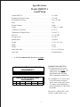
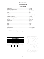
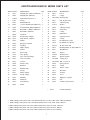
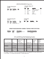
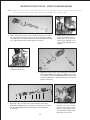
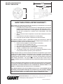
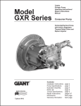
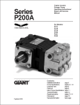
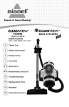
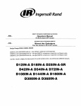
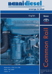
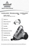
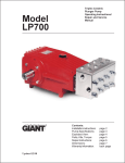
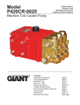
Triplex Ceramic Plunger Pump Operating Instructions/ Repair and Service Manual Models HR2527A/HR3025/ HR3030 Pumps Consumer Pumps HR2527A shown MADE IN THE USA Updated 5/02 Contents: Installation Instructions: Pump Specifications: Exploded View: Parts List: Kits/Torgue Specs: Touble Shooting Repair Instructions: Dimensions/Warranty: page 2 pages 3-5 page 6 page 7 page 8 page 9 page 10-11 back page INSTALLATION INSTRUCTIONS Installation of the Giant Industries, Inc., pump is not a complicated procedure, but there are some basic steps common to all pumps. The following information is to be considered as a general outline for installation. If you have unique requirements, please contact Giant Industries, Inc. or your local distributor for assistance. 1. The pump should be installed flat on a base to a maximum of a 15 degree angle of inclination to ensure optimum lubrication. 2. The inlet to the pump should be sized for the flow rate of the pump with no unnecessary restrictions that can cause cavitation. Teflon tape should be used to seal all joints. If pumps are to be operated at temperatures in excess of 800 F, it is important to insure a positive head to the pump to prevent cavitation. 3. The discharge plumbing from the pump should be properly sized to the flow rate to prevent line pressure loss to the work area. It is essential to provide a safety bypass valve between the pump and the work area to protect the pump from pressure spikes in the event of a blockage or the use of a shut-off gun. 4. Reverse rotation may be safely achieved by following a few guidelines available upon request from Giant Industries, Inc. Required horsepower for system operation can be obtained from the charts on pages 3 and 6. 5. Before beginning operation of your pumping system, remember: Check that the crankcase and seal areas have been properly lubricated per recommended schedules. Do not run the pump dry for extended periods of time. Cavitation will result in severe damage. Always remember to check that all plumbing valves are open and that pumped media can flow freely to the inlet of the pump. NOTE: An anti-sieze material must be applied to the engine cranckshaft to ensure trouble free disassembly of the pump. Finally, remember that high pressure operation in a pump system has many advantages. But, if it is used carelessly and without regard to its potential hazard, it can cause serious injury. IMPORTANT OPERATING CONDITIONS Failure to comply with any of these conditions invalidates the warranty. 1. Crankcase oil should be changed after the first 50 hours of operation. Then at regular intervals of 500 hours or less depending on operating conditions. Use Giant synthetic oil 2. Pump operation must not exceed rated pressure, volume, or RPM. A pressure relief device must be installed in the discharge of the system. 3. Acids, alkalines, or abrasive fluids cannot be pumped unless approval in writing is obtained before operation from Giant Industries, Inc. 4. Run the pump dry approximately 10 seconds to drain the water before exposure to freezing temperatures. NOTE: Contact Giant Industries for Service School Information. Phone: (419)-531-4600 2 Specifications Model HR2527A Axial Pump Volume HR2527A .................................................................................2.5 GPM Maximum Discharge Pressure .............................................................2750 PSI Maximum Inlet Pressure ......................................................................Up to 90 PSIG1 RPM .....................................................................................................3450 Plunger Diameter ..................................................................................16mm Stroke ....................................................................................................5.3mm (7.1 o angle) Crankcase Oil Capacity ........................................................................4.5 fl. oz. Temperature of Pumped Fluids .............................................................Up to 80 oF Inlet Port ...............................................................................................1 x 1/2" NPT Discharge Ports ....................................................................................3/8" NPT Shaft Rotation .......................................................................................Clockwise Weight ...................................................................................................11.7 lbs. (12.7 lbs.) Width .....................................................................................................6-9/16" Height ...................................................................................................7-25/32" Swash Plate Bore .................................................................................3/4" x 3/16" Keyway Valve Type ............................................................................................Polyamide Plastic 1 A 25 PSIG minimum inlet pressure is required. HR2527A ELECTRIC HORSEPOWER REQUIREMENTS RPM GPM 1000 PSI 1500 PSI 2000 PSI 2750 PSI 3450 2.5 1.7 2.6 3.4 4.7 HR2527A GAS HORSEPOWER REQUIREMENTS RPM GPM 1000 PSI 1500 PSI 2000 PSI 2750 PSI 3450 2.5 2.3 3.4 4.5 6.3 HORSEPOWER RATINGS: The rating shown are the power requirements for the pump. Gas engine power outputs must be approximately twice the pump power requirements shown above. We recommend a 1.15 service factor be specified when selecting an electric motor as the power source. To compute specific pump horsepower requirements, use the Following formula: Electric HP = (GPM X PSI) / 1460 Gas HP = (GPM X PSI) / 1100 3 Specifications Model HR3025 Axial Pump Volume HR3030....................................................................................3.0 GPM Maximum Discharge Pressure .............................................................2500 PSI Maximum Inlet Pressure ......................................................................Up to 90 PSIG1 RPM .....................................................................................................3450 Plunger Diameter ..................................................................................16mm Stroke ....................................................................................................5.9mm (8.0 o angle) Crankcase Oil Capacity ........................................................................4.5 fl. oz. Temperature of Pumped Fluids .............................................................Up to 80 oF Inlet Port ...............................................................................................1 x 1/2" NPT Discharge Ports ....................................................................................3/8" NPT Shaft Rotation .......................................................................................Clockwise Weight ...................................................................................................11.4 lbs. Width .....................................................................................................6-7/16" Height ...................................................................................................10-1/4" Swash Plate Bore .................................................................................3/4 x 3/16 Keyway Valve Type ............................................................................................Polyamide Plastic 1 A 25 PSIG minimum inlet pressure is required. HR3025 ELECTRIC HORSEPOWER REQUIREMENTS RPM GPM 1000 PSI 1500 PSI 2000 PSI 2500 PSI 3450 3.0 2.1 3.1 4.1 5.1 HR3025 GAS HORSEPOWER REQUIREMENTS RPM GPM 1000 PSI 1500 PSI 2000 PSI 2500 PSI 3450 3.0 2.7 4.1 5.5 6.8 HORSEPOWER RATINGS: The rating shown are the power requirements for the pump. Gas engine power outputs must be approximately twice the pump power requirements shown above. We recommend a 1.15 service factor be specified when selecting an electric motor as the power source. To compute specific pump horsepower requirements, use the Following formula: Electric HP = (GPM X PSI) / 1460 Gas HP = (GPM X PSI) / 1100 4 Specifications Model HR3030 Axial Pump Volume HR3030....................................................................................3.0 GPM Maximum Discharge Pressure .............................................................3000 PSI Maximum Inlet Pressure ......................................................................Up to 90 PSIG1 RPM .....................................................................................................3450 Plunger Diameter ..................................................................................16mm Stroke ....................................................................................................5.9mm (8.0 o angle) Crankcase Oil Capacity ........................................................................4.5 fl. oz. Temperature of Pumped Fluids .............................................................Up to 80 oF Inlet Port ...............................................................................................1 x 1/2" NPT Discharge Ports ....................................................................................3/8" NPT Shaft Rotation .......................................................................................Clockwise Weight ...................................................................................................11.4 lbs. Width .....................................................................................................6-7/16" Height ...................................................................................................10-1/4" Swash Plate Bore .................................................................................1"x3/16" Keyway Valve Type ............................................................................................Polyamide Plastic 1 A 25 PSIG minimum inlet pressure is required. HR3030 ELECTRIC HORSEPOWER REQUIREMENTS RPM GPM 1500 PSI 2000 PSI 2500 PSI 3000 PSI 3450 3.0 3.1 4.1 5.1 6.2 HR3030 GAS HORSEPOWER REQUIREMENTS RPM GPM 1500 PSI 2000 PSI 2500 PSI 3000 PSI 3450 3.0 4.1 5.5 6.8 8.2 HORSEPOWER RATINGS: The rating shown are the power requirements for the pump. Gas engine power outputs must be approximately twice the pump power requirements shown above. We recommend a 1.15 service factor be specified when selecting an electric motor as the power source. To compute specific pump horsepower requirements, use the Following formula: Electric HP = (GPM X PSI) / 1460 Gas HP = (GPM X PSI) / 1100 5 HR2527A/HR3025/HR3030 EXPLODED VIEW 6 HR2527A/HR3025/HR3030 SERIES PARTS LIST ITEM PART # DESCRIPTION 1* 1* 2 3 4 5** 5** 6 6 7 8A* 8B** 10 11 12 14 15 16 18 19 19A 20 22 28 34 36 37 38 39 41 42 43 Adapting Plate (HR2527A/HR3025) Adapting Plate (HR3030) Socket Head Cap Screw ¼ O-Ring Radial Shaft Seal 7.1o Piece Wobble Plate (HR2527A) 8o Wobble Plate (HR3025/HR3030) Steel Shaft ¾ (HR2527A/HR3025) Steel Shaft 1" (HR3030) Crankcase Rear Bearing, Complete Front Bearing, Complete Plunger Spring Disc Retainer Clip Ring Plunger Spring Oil Seal Spacer Ring Valve Spring Valve Cone (Discharge) Valve Cone (Inlet) V-Sleeve Pressure Ring Manifold Manifold Plug O-Ring Suction Flange O-Ring, Flange Stud Bolt Oil Fill Cap Oil Drain Plug Gasket 06311 06403 07881A 07344 07805 06419 06402 06393 06401 08089 06300 06301 06319 06318 06291 07873 06316 06317 07374 06295 06267 06315 06290 06424 07379 07913 06313 07910A 06320 08083 06273 08192 QTY. ITEM 46 47 48 49 50 51 52 54 56 58 59 62 63 64 66 67+ 69+ 72 75 76 77 78 79 80 81 84 87 88 89 90 91 1 1 8 1 1 1 1 1 1 1 1 1 3 3 3 3 3 3 6 3 3 3 3 1 3 1 1 1 3 1 1 1 + PART # 06423 07937 12031-0002 06227 06324 07917A 06608 06239 12007 07045 06524 12326 12325 12328 07935A 06414 07467 06224 23422A 06306 12516-001 23010-0100 23009 06312 06339 12517 07044 07046 08250 07939 07068 09502 DESCRIPTION QTY. Piston 1 O-Ring 2 Back-Up Ring 2 Ball, By Pass Valve 1 Adjusting Plug 1 Washer 1 Adjusting Spring 1 Guide Plug 1 O-Ring 8 Handwheel 1 Adjusting Screw 1 O-Ring 1 Kick-Back Valve Cone 1 Kick-Back Valve Spring 1 By Pass Valve Seat 1 Mounting Flange "X" Style (HR2527) 1 Bolt (HR2527) 4 Washer 3 Thermal Valve 1 Injector Retainer 1 O-Ring Viton 1 Ball, 7/32 Dia. ss 1 Spring, Injector 1 O-Ring 1 Oriface, 2.1mm 1 Hose Barb 1 Locknut 1 Cover 1 Sightglass w/gasket 1 Nut 1 Locknut w/Nylon Insert 1 Gasoline Flange kit * When ordering a 06311 please order 17021 which includes 06311, 07344, 07805, 06300 - HR2527A/HR3025 * When ordering a 06403, please order 17038 which includes 06403, 07344, 07805, 06300 - HR3030 ** When ordering 06419, please order 17036, which includes 06419, 06393, & 06301 - HR2527A ** When ordering 06402, please order 17051, which includes 06402, 06393 & 06301 - HR3025 ** When ordering 06402, please order 17040, which includes 06402, 06401, & 6301 - HR3030 7 HR2527A/HR3025/HR3030 Repair Kits Plunger Packing Kit # 09465 Item 22 20 Part # 06290 06315 Description Pressure Ring V-Sleeve 3 Unloader Repair Kit # 09235 Valve Assembly Kit # 09475 Item 18 19A 19 Part # 07374 06267 06295 Item 36 47 48 49 56 62 66 Qty. 3 Description Qty. Valve Spring 6 Guided P-Valve 3 Discharge Valve Cone 3 Part # 07913 07937 12031-0002 06227 12007 12326 07935A Oil Seal Kit # 09468 Item 15 Part # 06316 Description O-Ring O-Ring, Adjusting Screw Teflon Back-Up Ring 8mm Ball O-Ring O-Ring By Pass Seat Description Plunger Oil Seal Qty. 1 2 2 1 2 1 1 Qty. 3 HR2527A/HR3025/HR3030 SERIES TORQUE SPECIFICATIONS Position 2 39 Item# Description 07881A 06320 Torque Amount (ft.-lbs) Socket Head Cap Screw 1/4" Stud Bolt 100in-lbs. 360in-lbs. GX and HR Pump Part Numbering System Injector Size Thremal Relief Valve Wobble Plate Shaft Bore 1=2.1 mm 1=1/2" 1=3/4" GX or HR Series Flow Pressure (in 100 psi increments) Vertical 20=GPM 25=2500 PSI Horizontal 23=GPM 2=1.8mm 2=7/8" 25=GPM 3=2.3mm 3=1" 4=5/8 GX or HR 2.5 25 - 1 1 1 For example, a GXV2525-112 is a GX pump that produces 2.5 GPM @ 2500 PSI, has a injector with a 2.1mm Oriface, 1/2" thermal relief valve and 7/8" wobble plate bore. 8 PUMP TROUBLE SHOOTING MALFUNCTION CAUSE REMEDY The Pressure and/or the Delivery Drops Worn packing seals Broken valve spring Worn or Damaged nozzle Fouled discharge valve Fouled inlet strainer Worn or Damaged hose Worn or Plugged relief valve on pump Cavitation Replace packing seals Replace spring Replace nozzle Clean valve assembly Clean strainer Repair/Replace hose Clean,Reset,andReplacewornparts Check suction lines on inlet of pump for restrictions Water in crankcase High humidity Worn seals Reduce oil change interval Replace seals Noisy Operation Worn bearings Replace bearings, Refill crankcase oil with recommended lubricant Check inlet lines for restrictions and/or proper sizing Cavitation Worn packing Inlet restriction Replace packing Check system for stoppage, air leaks, correctly sized inlet plumbing to pump Cavitation Check inlet lines for restrictions and/or proper size Pressure Drop at Gun Restricted discharge plumbing Re-size discharge plumbing to flow rate of pump Excessive Leakage Worn plungers Worn packing/seals Excessive vacuum Inlet pressure too high Replace plungers Adjust or Replace packing seals Reduce suction vacuum Reduce inlet pressure High Crankcase Temperature Wrong Grade of oil Improper amount of oil in crankcase Giant oil is recommended Adjust oil level to proper amount Rough/Pulsating Operation with Pressure Drop 9 REPAIR INSTRUCTIONS - HR2527A/HR3025/HR3030 NOTE: 1. Always take time to lubricate all metal and nonmetal parts with a light film of oil before reassembly. This step will ensure proper fit, at the same time protecting the pump's nonmetal parts (elastomers) from cutting and scoring. With a 19mm socket wrench, remove the three discharge valve plugs (34). Inspect the valve plug o-rings (56) for wear, and replace as necessary. Remove the valve spring (18) and valve cone (19) from the manifold (28). Inspect the parts for wear and replace as necessary. 2. With a 19mm crescent wrench, remove the adjusting screw assembly (50, 56, 47, and 59). Unscrew the adjusting screw (59) from the adjusting screw plug (50). 36 63 62 3. With a crescent wrench, remove the injector retainer (76). 64 4. Inspect the o-ring (36) for wear and replace as necessary. Remove the kickback valve spring (64), kickback valve cone (63), and the o-ring (62) from the manifold (28). Inspect and clean the siphon injector and ball clean parts for wear and replace as necessary. 49 5. 51 52 59 47 56 58 Inspect the o-rings (56 and 47) for wear and replace as necessary. Remove the adjusting spring (52), washer (51) and by pass valve ball (49) from the manifold (28). Inspect the parts for wear and replace as necessary. 10 6. Next, remove the three manifold stud nuts (39) with a 17mm wrench. Remove the suction flange (37) and flange o-ring (38). Inspect the o-ring for wear and replace as necessary. REPAIR INSTRUCTIONS - HR2527A/HR3025/HR3030 NOTE: Always take time to lubricate all metal and nonmetal parts with a light film of oil before reassembly. This step will ensure proper fit, at the same time protecting the pump's nonmetal parts (elastomers) from cutting and scoring. 54 7. Tap the back of the manifold (28) with a rubber mallet to dislodge, and slide off the plungers (10). Take note of the position of the discharge port so as to place the port in the same position during reassembly. 74 9. 16 22 20 8. 56 48 47 48 46 66 With a 19mm socket wrench, remove the guide plug (54) and o-ring (56) from the manifold (28). Remove the piston (46), o-ring (47), and backup rings (48). Using a 7/32" Allen wrench, remove the bypass valve seat (66). Inspect the parts for wear and replace as necessary. 18 19A Remove the valve cones (19A), valve springs (18), v-sleeves (20) and pressure rings (22). Inspect for wear and replace as necessary. Remove the spacer ring (16) and flinger (56) from the plungers (10). 10. If the crankcase oil seals (15) are to be replaced, they can be removed by prying loose with a small screwdriver. Take care not to make contact with the plunger (10) and pry out the oil seals from their housing. 11. Reassemble in reverse order. Fill the crankcase until the proper amount of oil (see specifications page 3). The pump is now ready for operation. Contact Giant Industries for service school information. Phone: (419) 531-4600 11 11.25 (HR3030) 9.75 (HR2527A/HR3025) HR2527A/HR3025/HR3030 SERIES DIMENSIONS 6.44 GIANT INDUSTRIES LIMITED WARRANTY Giant Industries, Inc. pumps and accessories are warranted by the manufacturer to be free from defects in workmanship and material as follows: 1. For portable pressure washers and self-service car wash applications, the discharge manifolds are guaranteed for the life of the pump. Our other pump parts, used in portable pressure washers and in car wash applications, are warranted for five years from the date of shipment for all pumps used in NON-SALINE, clean water applications. 2. One (1) year from the date of shipment for all other Giant industrial and consumer pumps. 3. Six (6) months from the date of shipment for all rebuilt pumps. 4. Ninety (90) days from the date of shipment for all Giant accessories. This warranty is limited to repair or replacement of pumps and accessories of which the manufacturers evaluation shows were defective at the time of shipment by the manufacturer. The following items are NOT covered or will void the warranty: 1. Defects caused by negligence or fault of the buyer or third party. 2. Normal wear and tear to standard wear parts. 3. Use of repair parts other than those manufactured or authorized by Giant. 4. Improper use of the product as a component part. 5. Changes or modifications made by the customer or third party. 6. The operation of pumps and or accessories exceeding the specifications set forth in the Operations Manuals provided by Giant Industries, Inc. Liability under this warranty is on all non-wear parts and limited to the replacement or repair of those products returned freight prepaid to Giant Industries which are deemed to be defective due to workmanship or failure of material. A Returned Goods Authorization (R.G.A.) number and completed warranty evaluation form is required prior to the return to Giant Industries of all products under warranty consideration. Call (419)-531-4600 or fax (419)-531-6836 to obtain an R.G.A. number. A complete copy of our current RGA policy may be obtained from Giant Industries by written request. Repair or replacement of defective products as provided is the sole and exclusive remedy provided hereunder and the MANUFACTURER SHALL NOT BE LIABLE FOR FURTHER LOSS, DAMAGES, OR EXPENSES, INCLUDING INCIDENTAL AND CONSEQUENTIAL DAMAGES DIRECTLY OR INDIRECTLY ARISING FROM THE SALE OR USE OF THIS PRODUCT. THE LIMITED WARRANTY SET FORTH HEREIN IS IN LIEU OF ALL OTHER WARRANTIES OR REPRESENTATION, EXPRESS OR IMPLIED, INCLUDING WITHOUT LIMITATION ANY WARRANTIES OR MERCHANTABILITY OR FITNESS FOR A PARTICULAR PURPOSE AND ALL SUCH WARRANTIES ARE HEREBY DISCLAIMED AND EXCLUDED BY THE MANUFACTURER. GIANT INDUSTRIES, INC., 900 N. Westwood Ave., P.O. Box 3187, Toledo, Ohio 43607 PHONE (419) 531-4600 FAX (419) 531-6836, www.giantpumps.com Ó Copyright 2001 Giant Industries, Inc. 3/01 HR2527A/HR3030.PM6