1
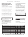
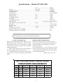
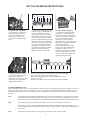
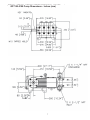
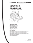
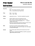
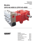
Triplex Ceramic Plunger Pump Manual Model GP7155-5100 Contents: Installation Instructions: Preventive Maintenance and Spare Parts List: Pump Specifications: Exploded View: Parts List/Kits: Repair Instructions: Dimensions: Warranty Information: page 2 page2 page 3 page 4 page 5 page 6 page 7 back page INSTALLATION INSTRUCTIONS Installation of the Giant Industries, Inc., pump is not a complicated procedure, but there are some basic steps common to all pumps. The following information is to be considered as a general outline for installation. If you have unique requirements, please contact Giant Industries, Inc. or your local distributor for assistance. further reduce system pulsation. Dampeners can also reduce the severity of pressure spikes that occur in systems using a shut-off gun. A dampener must be positioned downstream from the unloader. 5. Crankshaft rotation on Giant Industries, Inc. pumps should be made in the direction designated by the arrows on the pump crankcase. Reverse rotation may be safely achieved by following a few guidelines available upon request from Giant Industries, Inc. Required horsepower for system operation can be obtained from the chart on page 3. 1. The pump should be installed flat on a base to a maximum of a 15 degree angle of inclination to ensure optimum lubrication. 2. The inlet to the pump should be sized for the flow rate of the pump with no unnecessary restrictions that can cause cavitation. Teflon tape should be used to seal all joints. If pumps are to be o operated at temperatures in excess of 140 F, it is important to insure a positive head to the pump to prevent cavitation. 6. Before beginning operation of your pumping system, remember: Check that the crankcase and seal areas have been properly lubricated per recommended schedules. Do not run the pump dry for extended periods of time. Cavitation will result in severe damage. Always remember to check that all plumbing valves are open and that pumped media can flow freely to the inlet of the pump. 3. The discharge plumbing from the pump should be properly sized to the flow rate to prevent line pressure loss to the work area. It is essential to provide a safety bypass valve between the pump and the work area to protect the pump from pressure spikes in the event of a blockage or the use of a shut-off gun. Finally, remember that high pressure operation in a pump system has many advantages. But, if it is used carelessly and without regard to its potential hazard, it can cause serious injury. 4. Use of a dampener is necessary to minimize pulsation at drive elements, plumbing, connections, and other system areas. The use of a dampener with Giant Industries, Inc. pumps is optional, although recommended by Giant Industries, Inc. to IMPORTANT OPERATING CONDITIONS Failure to comply with any of these conditions invalidates the warranty 2. Pump operation must not exceed rated pressure, volume, or RPM. A pressure relief device must be installed in the discharge of the system. 3. Acids, alkalines, or abrasive fluids cannot be pumped unless approval in writing is obtained before operation from Giant Industries, Inc. 1. Prior to initial operation, add oil to crankcase so that oil level is between the two lines on the oil dipstick. DO NOT OVERFILL. Use Giant Recommended Oil (p/n 01154), which is equivalent to SAE 85-90W Industrial Grear Lube. Crankcase oil should be changed after the first 50 hours of operation, then at regular intervals of 500 hours or less depending on operating conditions. Check 4. Run the pump dry approximately 10 seconds to drain the water before exposure to freezing temperatures. Preventative Maintenance Check-List & Recommended Spare Part List Daily Weekly 50hr Every Every Every 500 hr 1500 hr 3000hrs Oil Level / Quality Oil Leaks Water Leaks Belts, Pulley Plumbing Oil Change (p/n 01154) Plunger Packing Kits(1 kit/Pump) See page 5 for kit list Oil Seal Kit ( 1 kit/Pump See page 5 for kit list) Valve Assembly Kit ( 1 kit/pump) See page 5 for kit list X X X X X Recommended Spare Part X X X X X NOTE: Contact Giant Industries for Service School Information. Phone: (419)-531-4600. 2 Specifications - Model GP7155-5100 U.S. ........................................... Metric Volume .............................................................................. 65.8 GPM .................................. 250 LPM Discharge Pressure ........................................................... 1500 PSI .................................... 100 Bar Crankshaft Speed .................................................................................................................. 700 RPM Inlet Pressure ........................................................................................................................ Up to 700 RPM Plunger Diameter .............................................................. 2.17” .......................................... 55mm Plunger Stroke .................................................................. 2.05” .......................................... 52mm Crankshaft Diameter ......................................................... 1.89” .......................................... 48mm Key Width ......................................................................... 0.55” .......................................... 14mm Crankshaft Mounting ............................................................................................................ Either side Shaft Rotation ............................................................................................. Top of pulley towards manifold Max.Temperature of Pumped Fluids ................................ 140 oF ........................................ 60 oC Inlet Ports ............................................................................................................................. (2) 2-1/2" NPT Discharge Ports ..................................................................................................................... (2) 1-1/4" NPT Weight ............................................................................... 374 lbs. ...................................... 170 kg Crankcase Oil Capacity .................................................... 1.6 Gal. ...................................... 6.0 liters Mechanical Effecency @ 700 RPM ..................................................................................... 0.83 Volumetric Effecency @ 700 RPM ...................................................................................... 0.96 Consult the factory for special requirements that must be met if the pump is to operate beyond one or more of the limits specified above. PULLEY INFORMATION Pulley selection and pump speed are based on a 1725 RPM motor and "B" section belts. When selecting desired GPM, allow for a ±5% tolerance on pumps output due to variations in pulleys, belts and motors among manufacturers. 1. Select GPM required, then select appropriate motor and pump pulley from the same line. 2. The desired pressure is achieved by selecting the correct nozzle size that corresponds with the pump GPM. HORSEPOWER INFORMATION Horsepower ratings shown are the power requirements for the pump. Gas engine power outputs must be approximately twice the pump power requirements shown above. We recommend that a 1.1 service factor be specified when selecting an electric motor as the power source. To compute specific pump horsepower requirements, use the following formula: (GPH X PSI) / 1450 = HP GP7155-5100 PULLEY SELECTION & HORSEPOWER REQUIREMENTS RPM 479 531 585 638 700 GPM 800 PSI 1000 PSI 1300 PSI 1500 PSI 45.0 25.7 32.1 41.8 48.2 49.9 28.5 35.6 46.3 53.5 55.0 31.4 39.3 51.1 58.9 60.0 34.3 42.9 55.7 64.3 65.8 37.6 47.0 61.1 70.5 3 Exploded View - GP7155-5100 4 Spare Parts List - GP7155-5100 ITEM 1 2 4 5 8 9 10 11 12 13 14 15 16 20 20A 21 22 23 24 25 28 30 30A 30B 30C 30D 31 32 32A 33 33A 33B 33C 34 36 36A 36B 36C 36D 38 38A 38B 39 PART 07600 13000 07601 07602 07603 01009 13133 07109-0400 07109 07182 07607 07608 07184 07610 07611 07612 13405 07614 13182 13183-0100 13184 07619 07225-0100 13136 08280 13154 07623 07624 07625 06950 07627 06951 07249 13137 07706-0100 07667-0100 07666 07664-0100 07755-0100 13155-0100 13156 07721 13157-0100 DESCRIPTION Crankcase Oil Filler Plug Assembly Crankcase Cover Gasket, Crankcase Cover Oil Dip Stick O-Ring, Dip Stick Hexagon Screw Spring Washer Drain Plug Gasket, Drain Plug Bearing Cover Radial Shaft Seal O-Ring Taper Roller Bearing Fitting Disc (Shim) Shaft Protector Crankshaft Key Connecting Rod Assy. Crosshead Assy. Crosshead Pin Cover Plate Hexagon Screw Grommet Washer Cover Plate Eye Bolt Radial Shaft Seal Shaft Seal Seal Retainer O-Ring Circlip Fitting Disc Oil Scraper Plunger Pipe Assy. Plunger Connection Plunger Pipe Tension Screw Steel Ring Seal Case O-Ring O-Ring Seal Sleeve QTY. 1 1 1 1 1 1 12 12 3 2 2 2 2 2 1-5 1 1 1 3 3 3 1 8 4 8 1 1 3 3 3 3 3 3 3 3 3 3 3 3 3 3 3 3 ITEM 39B 39C 39D 41 42 43 45 49 49A 50 50A 50B 51 51A 51B 51C 51D 51E 51F 51G 51H 56 56A 56B 56C 56D 57 58 59 59A 60 61 66 67 68 68A 69 70 71 72 73 74 75 Plunger Packing Kit - # 09609 Item 38A 38B 42 Part # 13156 07721 07711 Description O-Ring O-Ring V-Sleeve Part # 07624 07625 07627 Description Radial Shaft Seal Shaft Seal O-Ring DESCRIPTION Compact Ring Support Disc Clip Ring Sleeve Support Ring V-Sleeve Pressure Ring Pressure Spring Stud Bolt Hex Nut Valve Casing Cylinder Stud Discharge Casing Valve Assembly Spring Tension Cap Valve Spring Guide Valve Spring Valve Plate Valve Seat O-Ring Support Ring O-Ring Valve Adaptor O-Ring for 56 Support Ring for 56A Support Ring for 56D O-Ring Tension Spring Hexagon Screw Plug, 1/2” BSP Steel Ring Plug, 1-1/4” BSP Plug, 2-1/2” BSP Disc For Crankshaft Hexagon Screw Screw-in Connector Plug, 1/8” BSP Steel Ring Threaded Elbow Elbow joint Curved leakage pipe Pipe Bend,180o Pipe Bend, 90o Straight leakage pipe QTY. 3 3 3 3 9 3 3 8 8 1 2 1 6 6 6 6 6 6 6 6 6 3 3 3 3 3 6 8 1 1 1 1 1 1 5 1 6 3 2 1 1 1 1 Valve Kit - # 09606 Qty. 3 3 9 Item 51B 51C 51D 51E 51F 51G 51H 56A 56B 56C 56D Oil Seal Kit - # 09221 Item 32 32A 33A PART 07723-0100 07797-0100 05218 05219 07711 07712-0100 05220 13159 06958 07790-5000 13162 05221 08288-0100 08281 08282 07732-0100 13164-0100 08283 07653-0001 13166 06613 05222 07658 07635 13168 07653 13173 05223 07109-0400 06807 12251-0100 12252-0100 13362 13358 06588 06589 07204-0100 06768 05224 05225 05226 05227 05228 Qty. 3 3 3 5 Part # 08282 07732-0100 13164-0100 08283 07653-0001 13166 06613 07658 07635 13168 07653 Description Valve Spring Guide Valve Spring Valve Plate Valve Seat O-Ring Support Ring O-Ring O-Ring Support Ring Support Ring O-Ring Qty. 1 1 1 1 2 2 2 2 2 1 1 GP7155-5100 REPAIR INSTRUCTIONS 57 58 51C 56 51E 51A 57 51 51D To Check Valve Assemblies 1. Loosen plugs (58), take out tension spring (57) and then remove the complete valve assembly (51) with either a valve tool or an M16 hexagon screw. 2. Remove valve adapter (56) and tension spring (57) with pull-out tool size 5. There is an O-ring (51G) under both the suction and the discharge valve each of which can be removed with a bent piece of wire.To disassemble unscrew the spring tension cap (51A) and press the valve seat (A) out of the spacer pipe (E). Check sealing surfaces and replace worn parts. Check Orings and support rings. Reinstall all parts in reverse order and tighten plugs (58) to 107 ft. lbs. 36B 4. Separate plunger connection (36A) from crosshead (25) by means of two open-end wrenches (size 22 and 27). Pull seal sleeves (39) out of their fittings in the crankcase. 39A 39 43 To Check Seals & Plungers. 3.Loosen nuts (49A) and remove pump head. CAUTION: Don't loosen the 3 plunger connections (36A) before the valve casing has been removed otherwise the tension screw (36C) could hit against the spacer pipe (51E) when the pump is being turned. Seal life can be increased if the pretensioning allows for a little leakage. This assists lubrication and keeps the seals cool. It is therefore not necessary to replace seals before the leakage becomes too heavy and causes output and operating pressure to drop. 42 42 41 38 5. Take seal case (38) out of seal sleeve (39). Examine plunger parts (36A-36D), seals (42,39A) and O-rings. When replacing plunger pipe (36B), tighten tension screws (36C) to 30 ft. lbs. Replace worn parts; grease seals with silicone before installing TO DISASSEMBLE GEAR Take out plunger and seal sleeves as described above. Drain oil. After removing the circleclip ring (33B), lever out seal retainer (33) with a screw driver. Check seals (32, 32A, 33A) and surfaces of crosshead. Remove crankcase cover (4). Loosen inner hexagon screws on the connecting rods (24) and push con rod halves as far into the crosshead guide as possible. Note: Connecting rods are marked for identification. Do not twist con rod halves. Con rod is to be reinstalled in the same position on shaft journals.Check surfaces of connecing rod and crankshaft (22) take out bearing cover to one side and push out crankshaft taking particular care that the conrod doesn't gt bent. Note: Seal (32A) must always be installed so taht the seat up on the inside diameter faces the oil. Reassemble in reverse order: Regulate axial bearing clearance minimum 0.1mm, maximum 0.15-by means of fitting disc (20A) shaft should yturn easily with little clearance. Tighten inner hexagon screws to 30 ft. lbs. Note: Connecting rod has to be able to be slighty moved sidewise at the stroke journals. 6 GP7150A, GP7155A, GP7255A SERIES DIMENSIONS - INCHES (mm) GP7155-5100 Pump Dimensions - Inches (mm) 7 GIANT INDUSTRIES LIMITED WARRANTY Giant Industries, Inc. pumps and accessories are warranted by the manufacturer to be free from defects in workmanship and material as follows: 1. For portable pressure washers and self-service car wash applications, the discharge manifolds will never fail, period. If they ever fail, we will replace them free of charge. Our other pump parts, used in portable pressure washers and in car wash applications, are warranted for five years from the dateof shipment for all pumps used in NON-SALINE, clean water applications. 2. One (1) year from the date of shipment for all other Giant industrial and consumer pumps. 3. Six (6) months from the date of shipment for all rebuilt pumps. 4. Ninety (90) days from the date of shipment for all Giant accessories. This warranty is limited to repair or replacement of pumps and accessories of which the manufacturer’s evaluation shows were defective at the time of shipment by the manufacturer. The following items are NOT covered or will void the warranty: 1. Defects caused by negligence or fault of the buyer or third party. 2. Normal wear and tear to standard wear parts. 3. Use of repair parts other than those manufactured or authorized by Giant. 4. Improper use of the product as a component part. 5. Changes or modifications made by the customer or third party. 6. The operation of pumps and or accessories exceeding the specifications set forth in the Operations Manuals provided by Giant Industries, Inc. Liability under this warranty is on all non-wear parts and limited to the replacement or repair of those products returned freight prepaid to Giant Industries which are deemed to be defective due to workmanship or failure of material. A Returned Goods Authorization (R.G.A.) number and completed warranty evaluation form is required prior to the return to Giant Industries of all products under warranty consideration. Call (419)-531-4600 or fax (419)-531-6836 to obtain an R.G.A. number. Repair or replacement of defective products as provided is the sole and exclusive remedy provided hereunder and the MANUFACTURER SHALL NOT BE LIABLE FOR FURTHER LOSS, DAMAGES, OR EXPENSES, INCLUDING INCIDENTAL AND CONSEQUENTIAL DAMAGES DIRECTLY OR INDIRECTLY ARISING FROM THE SALE OR USE OF THIS PRODUCT. THE LIMITED WARRANTY SET FORTH HEREIN IS IN LIEU OF ALL OTHER WARRANTIES OR REPRESENTATION, EXPRESS OR IMPLIED, INCLUDING WITHOUT LIMITATION ANY WARRANTIES OR MERCHANTABILITY OR FITNESS FOR A PARTICULAR PURPOSE AND ALL SUCH WARRANTIES ARE HEREBY DISCLAIMED AND EXCLUDED BY THE MANUFACTURER. GIANT INDUSTRIES, INC. 900 N. Westwood Ave. P.O. Box 3187 Toledo, Ohio 43607 (419) 531-4600 FAX (419) 531-6836 Copyright 2006 Giant Industries, Inc. 08/06 GP7155-5100.PMD