1
Maintenance
Manual
3600 Bar Code Label Printer
P/N 062905-001
c 3 9 frank
Intermec Corporation
6001 36th Avenue West
P.O. Box 4280
Everett, WA 98203-9280
U.S. technical and service support: 1-800-755-5505
U.S. media supplies ordering information: 1-800-227-9947
Canadian technical and service support: 1-800-688-7043
Canadian media supplies ordering information: 1-800-268-6936
Outside U.S. and Canada:
Contact your local Intermec service supplier.
The information contained herein is proprietary and is provided solely for the purpose of allowing
customers to operate and/or service Intermec manufactured equipment and is not to be released,
reproduced, or used for any other purpose without written permission of Intermec.
Information and specifications in this manual are subject to change without notice.
1995 by Intermec Corporation
All Rights Reserved
The word Intermec, the Intermec logo, Label Debut, and CrossBar are trademarks of Intermec
Corporation.
The name Centronics is wholly owned by GENICOM Corporation.
IBM is a registered trademark of International Business Machines Corporation.
Throughout this manual, trademarked names may be used. Rather than put a trademark ( )
symbol in every occurrence of a trademarked name, we state that we are using the names only in an
editorial fashion, and to the benefit of the trademark owner, with no intention of infringement.
The software contained in the 3600 printer and the accompanying materials are copyrighted.
Unathorized copying of the software, including software that has been modified, merged, or
included with other software, or the written materials is expressly forbidden without the prior
written consent of Intermec. All right, title, and interest in all copies of this software are and shall at
all time remain the sole and exclusive property of Intermec. Customer may be held legally
responsible for any copyright infringement that is caused or encouraged by its failure to abide by
these terms.
hc nug
c 3
Contributors
Technical Writer:
Robert Shaw
Editor:
Craig Thompson
Technical Illustrator:
George Wilson
Technical Reviewers:
Cathy Aragon
Pixie Austin
Daniel Clark
John Cramer
Allen Crowe
Stephen Eckert
Pat Helton
Laura McCluer
Ed Millet
Art Millican
Matt Roberts
Joe Wade
iii
hc
c 3 9 frank
hc nug c 3 9 frank
Contents
Contents
Before You Begin xi
Safety Summary xi
Warnings and Cautions xii
Purpose of This Manual xii
Additional Information xv
1
General Information
Overview of the 3600 Printer 1-3
3600 Features 1-4
3600 Printer Specifications 1-4
Dimensions (no options installed) 1-4
Electrical Requirements 1-4
Printing Methods 1-4
Printing Speed 1-5
Printhead Specifications 1-5
Media Specifications 1-5
Ribbon Specifications 1-5
Environment 1-5
Self-Strip Specifications 1-5
Communications 1-6
Fonts and Graphics 1-6
Character Sets 1-6
Memory 1-6
Factory Default Settings 1-7
3600 Printer Options 1-7
Memory Expansion 1-7
Twinax Interface 1-7
Coax Interface 1-8
Parallel Interface 1-8
Network Connectivity 1-8
Kanji/Katakana Character Support 1-8
Batch Takeup 1-8
v
3600 Printer Maintenance Manual
Principal Functional Parts 1-9
Basic Printer Setup and Operation 1-11
Front Panel Operation 1-11
Over-Temperature 1-11
Media or System Faults 1-12
Feed/Pause Pushbutton 1-12
Checking the Printer Configuration 1-12
DIP Switch Settings 1-13
Connecting the Printer to a Computer 1-13
Printing 1-14
Using Label Debut 1-14
Using Third-Party Software 1-14
Using the Printer Command Set 1-15
2
Preventive Maintenance
Preventive Maintenance Actions and Intervals 2-3
Inspecting the Printer 2-4
Cleaning the Printer 2-4
Removing the Media Cover 2-5
Cleaning the Printhead 2-6
Cleaning the Rollers and Tear Bar 2-8
Cleaning the Media Guides and Media Path 2-9
Cleaning the Label and Ribbon Sensors 2-11
Cleaning the Printer Covers 2-12
3
vi
Testing and Adjusting
Testing the Printer 3-3
Running Test and Service Mode at the Printer 3-4
Setting DIP Switches 3-4
Printing Test Labels 3-7
Running Test and Service Mode From a Host Computer 3-11
Testing Printer and Host Communications 3-12
hc nug c 3 9 frank
Contents
Adjusting the Printer 3-13
Adjusting the Print Bias for Print Quality 3-14
Adjusting the Print Intensity 3-15
Adjusting the Printhead Adjustment Lever for Print Quality 3-16
Adjusting the Label Mark Sensor 3-17
Adjusting the Label Gap Sensor 3-19
Adjusting the Label Taken Sensor 3-20
Aligning the Printer 3-21
Aligning the Rollers 3-22
Aligning the Printhead 3-23
Aligning the TTR Supply Hub 3-25
4
Troubleshooting
About Troubleshooting and Repair 4-3
Troubleshooting Tips 4-3
Where to Start 4-3
Repair 4-3
Troubleshooting Checklist 4-4
Error Handling 4-5
Syntax Errors 4-5
Parameter Errors 4-5
Image Overrun Errors 4-5
Invalid Numeric Character Errors 4-6
Insufficient Storage RAM Errors 4-6
Error Codes 4-6
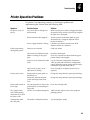
Printer Operation Problems 4-9
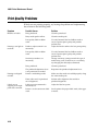
Print Quality Problems 4-10
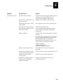
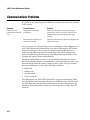
Communications Problems 4-12
Environmental Problems 4-13
Electrostatic Discharge (ESD) 4-13
Electromagnetic and Radio Frequency Interference 4-14
Ground Loops Between Equipment 4-14
Inadequate Earth Ground 4-14
AC Power Problems (Surges, Sags, Spikes, Noise, and Outages) 4-15
Miscellaneous Problems 4-16
vii
3600 Printer Maintenance Manual
5
Remove and Replace Procedures
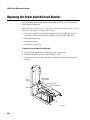
Replacing Printer Components 5-3
Replacing the Lithium Battery 5-4
Replacing the Printhead 5-5
Replacing the Bezel PCB 5-6
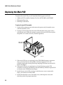
Replacing the Main PCB 5-8
Replacing the Kanji/Katakana Option PCB 5-9
Replacing the Label Mark Sensor 5-10
Replacing the Label Taken Sensor 5-12
Replacing the Label Gap Sensor 5-13
Replacing the TTR Drive Roller and Gear/Pulley 5-15
Replacing the TTR Takeup Hub, Clutch/Pulley, and Belt 5-18
Replacing the TTR Supply Hub and Adjusting Plate 5-20
Replacing the Platen Roller and Gear 5-22
Replacing the Liner Drive and Takeup Components 5-24
Replacing the Stepper Motor 5-30
Replacing the AC Plug/Input Filter 5-31
Replacing the Power Switch/Circuit Breaker 5-32
Replacing the Transformer 5-33
6
7
viii
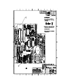
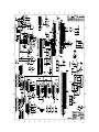
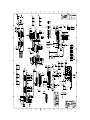
PCB Drawings and Schematics
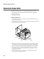
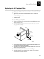
Replacement Parts
hc nug c 3 9 frank
A
Contents
Appendix
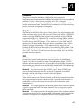
Functional Description of the 3600 Mechanics A-3
Functional Description of the 3600 Electronics A-4
Power Supply A-4
+5V A-4
+40V A-4
+24V A-4
Power Fail Detection A-5
Battery A-5
Battery Life Calculations A-5
Reset A-5
Motor Driver A-6
Processor A-7
Chip Selects A-7
TPU A-7
QSM A-8
Interrupt Priority Levels A-8
Crystal A-8
Memory A-9
Static RAM A-9
EPROM A-9
DRAM A-9
Communications Interface A-10
A/D Converter A-10
DIP Switches A-10
ASIC and I/O Option Interface A-10
Address/Data Multiplexor A-10
Chip Select Generation A-11
I/O Option Connector A-11
FIFO A-11
Front Panel Interface A-11
Debug Interface A-11
Functional Description of the 3600 Software A-14
Band Buffering and Font Caching A-14
Image Band Buffering A-14
Image Band Example A-15
Font Caching A-18
Print Energy Compensation A-18
Digital Thermal Compensation A-18
Global Compensation A-18
ix
hc nug c 3 9 frank
Before You Begin
Before You Begin
This section describes the purpose and arrangement of this manual to you. It is
intended to bring to your attention, important general safety concerns, specific
warnings and cautions, and sources of additional information.
Safety Summary
Your safety is extremely important. Read and follow all of warnings and
cautions in this book before handling and operating Intermec equipment. You
can be seriously injured, and equipment and data can be damaged if you do
not follow the safety warnings and cautions.
Do Not Repair or Adjust Alone Do not repair or adjust energized equipment
alone under any circumstances. Someone capable of providing first aid must
always be present for your safety.
First Aid Always obtain first aid or medical attention immediately after an
injury. Never neglect an injury, no matter how slight it seems.
Resuscitation Begin resuscitation immediately if someone is injured and stops
breathing. Any delay could result in death or permanent injury. To work on or
near high voltage, you should be familiar with approved industrial first aid
methods.
Energized Equipment Never work on energized equipment unless you are
authorized by a responsible authority. Energized electrical equipment is
dangerous. Electrical shock from energized equipment can cause death. If you
must perform authorized emergency work on energized equipment, be sure
that you comply strictly with approved safety regulations.
xi
3600 Printer Maintenance Manual
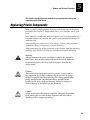
Warnings and Cautions
The warnings and cautions in this manual use the following format and
address the issues described:
WARNING
CAUTION
Warning
A warning alerts you of an operating procedure, practice, condition,
or statement that must be strictly observed to avoid death or
serious injury to the persons working on the equipment.
Caution
A caution alerts you to an operating procedure, practice, condition,
or statement that must be strictly observed to prevent equipment
damage or destruction, or corruption or loss of data.
Purpose of This Manual
The purpose of this maintenance manual is to provide the information you
need to clean, adjust, and repair the Intermec 3600 Bar Code Label Printer.
Who Should Read This Manual?
This manual is written for experienced electronic technicians trained by
Intermec, who will service and, if necessary, repair the 3600 printer. Detailed
operating instructions and specific related information is provided in the 3600
Bar Code Label Printer User’s Manual.
This document is not intended to support user operations or persons untrained
in troubleshooting and repair. You should have a working knowledge of
electronics with an advanced understanding of PCs, DOS, data
communications, and bar code applications. It is assumed that you are familiar
with the installation, programming, and operation of the Intermec 3600 Bar
Code Label Printer and all of its options, including a working knowledge of the
Label Debut (or Label) software tool.
xii
hc nug c 3 9 frank
Before You Begin
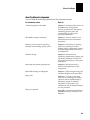
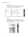
How This Manual Is Organized
You will find the following information in the referenced section:
For information about:
Refer to:
A basic description of the 3600
Chapter 1 - An illustrated overview of
the 3600 printer; listing printer
features, specifications, and options,
identifying primary parts, and
summarizing some setup and
operating information.
Scheduled cleanings and checks
Chapter 2 - Actions, intervals, and
illustrated preventive maintenance
procedures.
Making sure the printer is operating
correctly and providing quality results
Chapter 3 - Procedures for running
printer tests printing test labels,
printing out the configuration settings,
and for making printer adjustments
and alignments.
Problem solving
Chapter 4 - Information for
identifying, duplicating, isolating, and
eliminating conditions or failures in
the printer environment or the printer
components.
Removing and replacing components
Chapter 5 - Instructions for the
removal and replacement of key
components.
Main PCB drawings and diagrams
Chapter 6 - Engineering drawing and
schematic diagram of the main PCB.
Spare parts
Chapter 7 - Two lists of the spare
parts: one in ascending part number
sequence and one alphabetically by
description, keyed to exploded
illustrations of the printer. Part
numbers for tools and documentation
are also provided.
Theory of operation
Appendix - functional descriptions of
the 3600 mechanics, electronics, and
firmware.
xiii
3600 Printer Maintenance Manual
Terms and Conventions
The following terms and conventions occur throughout this manual. A
complete glossary of terms is provided in the 3600 Bar Code Label Printer User’s
Manual.
Terms
• “Backing” (or liner) refers to the silicon release portion of the media that
carries the label.
•
“Host” refers to any computer that the printer is connected to.
•
“TTR” refers to the thermal transfer ribbon used when the printer is in
thermal transfer rather than direct transfer mode.
•
“Media” is the stock on which the printer prints labels. Media can be made
of plain paper, polyester, thermally reactive paper, or other materials with
adhesive backing.
Conventions
The following conventions are used throughout this manual for operating
procedures and descriptions of the printer.
•
xiv
Downloaded commands appear in the order that you enter them into the
printer with the following conventions:
Convention
Description
<>
Angle brackets < > enclose mnemonic representations of
ASCII control characters. For example, <ETX> represents
the ASCII “End of Text” control character.
{}
Braces {} enclose variable data. For example, {n} signifies a
variable for which you can designate a constant value.
[]
Brackets around a word or letter represent a key on your
keypad. For example, [Tab] represents the Tab key and [M]
represents the letter M key.
[ ]-[ ]
When two keys are joined with a dash, press them
simultaneously. For example, if you see the command
[Ctrl]-[C], press the two keys at the same time.
E3;F3
Enter all characters not enclosed in brackets by pressing an
individual keypad key. For example, E3;F3; is entered as
[E][3][;][F][3][;] with the E and the F in uppercase.
hc nug c 3 9 frank
Before You Begin
Additional Information
The following documents may be of interest or help to you in servicing the
3600 printer.
3600 Bar Code Label Printer User’s Manual (P/N 062732)
Label Debut User’s Manual (P/N 062982)
Data Communications Reference Manual (P/N 044737)
The Bar Code Book by Roger C. Palmer
xv
c 3 9 frank
1
General Information
c 3 9 frank
c 3 9 frank
1
General Information
This chapter identifies basic features, options, and technical specifications of the
3600 printer. It names principal functional parts and reviews basic printer setup and
operation.
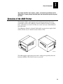
Overview of the 3600 Printer
The Intermec 3600 is a microprocessor-based thermal printer that prints
standard bar code or 2D symbology, human-readable characters, graphics,
lines, and borders on 3-inch (7.62 cm) to 6.6-inch (16.8 cm) wide continuous
feed label stock.
The 3600 prints directly to thermal label media or can print on regular label
media with the use of a thermal transfer ribbon (TTR).
Po
we
r
Al
er
t
pt
y/
Pa
us
e
1 2 3 4 5 6 7 8
Em
1 2 3 4 5 6 7 8
Fe
ed
/P
au
se
Inte
rme
c
36
00
I
O
3600M.001
The 3600 supports applications that need a wider print capability than the
Intermec 3400 Bar Code Label Printer can provide.
1-3
3600 Printer Maintenance Manual
c 3 9 frank
3600 Features
The 3600 printer’s features are summarized in the following list:
•
Print speed from 2 to 5 ips
•
Programmable, nonvolatile printer configuration
•
Bitmap font capabilities
•
Outline/vector font support
•
User selectable gap feature for fonts
•
2D symbology support (Code One, PDF 417, and Maxicode)
•
128k (standard), 512k (optional) storage memory
•
Autoselection of Intermec protocols
•
Printable control characters
•
Image banding and memory management
•
Dot-by-dot digital thermal compensation
•
Self-strip or continuous print (with internal rewind)
•
Media sensitivity numbering system
•
Wide range of label media
•
Label Debut
TM
label design software
3600 Printer Specifications
The specifications and performance parameters for the 3600 printer are
itemized in this section.
Dimensions (no options installed)
Height
11 inches (27.9 cm)
Width
12 inches (30.5 cm)
Length
17 inches (43.2 cm)
Weight
45 pounds (20.3 kg)
Electrical Requirements
Input Voltage 100, 115, or 230 VAC ± 10%
Frequency
47 to 63 Hz
Printing Methods
Direct Thermal
Thermal Transfer (thermal transfer ribbon (TTR) required)
1-4
c 3 9 frank
General Information
1
Printing Speed
Maximum
5 ips (50.8 mm per second)
Minimum
2 ips (127 mm per second)
The print speed can be changed in 1 ips increments only: 2, 3, 4, or 5.
Printhead Specifications
Element size
0.00492 inch square (0.13 mm)
Width
6.6 inches maximum print (168 mm)
Resolution
203 dots per inch (8 dots per mm)
# of Elements
1344 per printhead
X dimensions
10 mil to 50 mil or 0.25 mm to 1.27 mm,
5 mil (0.13 mm) in drag mode with specified media
Media Specifications
Roll
6,000 linear inches (152 m)
Length
0.5 inch (13 mm) to 17 inches (432 mm) (stripped media)
Width
3.0 inch (76 mm) to 6.7 inches (170 mm)
Thickness
0.012 inches (0.3 mm) maximum
Diameter
8.38 inch maximum diameter (213 mm)
Ribbon Specifications
Roll
6,000 linear inches (152 m)
Widths
3.0 inches (76 mm)
4.1 inches (104 mm)
5.4 inches (137 mm)
6.7 inches (170 mm)
Diameter
2.25 inches maximum (57 mm)
Environment
Operating
50°F to 104°F (10°C to 40°C)
Humidity
10% to 90% noncondensing
Self-Strip Specifications
The liner takeup hub can spool the backing of an entire 6,000-inch roll of
media.
Peel Release
10 to 50 grams
1-5
3600 Printer Maintenance Manual
c 3 9 frank
Communications
Asynchronous RS-232C, RS-422, RS-485 interfaces
Serial ASCII code
Hardware (Ready/Busy) flow control
XON/XOFF protocol
Intermec Standard Block protocol
Polling Mode D protocol
Multi-Drop protocol
Baud Rates: 1200, 2400, 4800, 9600, 19200
Fonts and Graphics
5x7, 7x9, 7x11, and 10x14 86XX compatible fonts
2 bitmap OCR fonts
3 bitmap fonts measured in point sizes 8, 12, and 20
1 outline font
12 monospaced bitmap fonts
Kanji/Katakana bitmap font card (option)
Kanji/Katakana bitmap and outline font card (option)
UDF size of 4 inches (101.6 mm) maximum
UDC size of 4 inches (101.6 mm) maximum
Character Sets
US ASCII
Norwegian/Danish
UK ASCII
Swedish/Finnish
German
Italian
French
Spanish
Swiss
Memory
1-6
Base
512K of DRAM for imaging
128K of SRAM for storage
Optional
512K of SRAM for storage
c 3 9 frank
General Information
1
Factory Default Settings
The following is a list of the factory default settings for the 3600 printer:
Configuration
Default Setting
Preamble Character
Disabled
Postamble Character
Disabled
Auto-Transmit 1
Disabled
Auto-Transmit 2
Disabled
Auto-Transmit 3
Disabled
Message Delay
0 ms
Power-Up Mode
Advanced mode
End-of-Print Skip Distance
100 dots
Top of Form
20 dots
Media Sensitivity
420
Number of Image Bands
3
Maximum Label Length
1000 dots
Printer Character Set
US ASCII
Label Retract
Enabled
Print Speed
3 ips
Label Stock Type
Die-cut
Intercharacter Delay
0 ms
3600 Printer Options
The 3600 you are servicing can be equipped with one or more of the following
options:
Memory Expansion
Storage memory for formats, pages, graphics, and fonts can be increased to
512K of battery backed static RAM. This option provides an additional 512K of
nonvolatile bulk storage to hold more formats, fonts, or bitmap graphics. It also
increases the printer’s image buffering capabilities.
Twinax Interface
Allows connection of the 3600 printer to IBM Twinax systems. The printer
emulates an IBM 5256 Model 1 printer and can operate with an IBM System
34/36/38 or AS/400 host computer.
1-7
3600 Printer Maintenance Manual
c 3 9 frank
Coax Interface
Allows connection of the 3600 printer to IBM coax systems. The 3600 emulates
an IBM 3287 printer by connecting the printer to IBM 3270 Type A coax cable
computer systems operating in the VTAM (CICS/IMS/TSO) or 8100 (DPPX)
environments. Connection can be made to an IBM 3174/76/99 system
controller/multiplexer.
Parallel Interface
This option lets the user connect the 3600 to a PC through any Centronics™
parallel interface in addition to the standard serial interface.
Network Connectivity
Using the Parallel Interface option and an Ethernet or other network adapter,
the 3600 can be connected to a network.
Kanji/Katakana Character Support
The 3600 has two Kanji/Katakana options: bitmap fonts only, or outline and
bitmap fonts. Users shipping finished materials or work in process materials to
Japan can meet Japanese label requirements for Kanji/Katakana (JIS
Interleaved 2 of 5).
Batch Takeup
A larger diameter liner takeup hub permits printed labels to be spooled for
later use without causing as much label curl as the smaller diameter hub. The
maximum takeup outside diameter is 5 inches.
1-8
c 3 9 frank
General Information
1
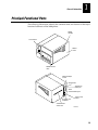
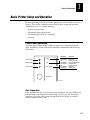
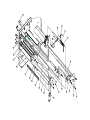
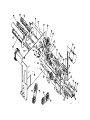
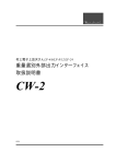
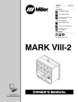
Principal Functional Parts
The following illustrations identify the common name and location of the major
functional elements of the 3600 printer.
Media
window
Front Panel
Pow
er
Ale
rt
Em
pty
/P
au
se
Media
cover
Fe
ed
/P
au
se
Inte
rme
c
36
00
Media access
door
Darkness adjust
control
DIP switches
1 2 3 4 5 6 7 8
Optional I/O
board port
1 2 3 4 5 6 7 8
Serial
communications port
I
O
AC power cord
receptacle
Power on/off
switch
Fanfold media
access slot
3600M.002
1-9
3600 Printer Maintenance Manual
c 3 9 frank
Media post
TTR supply hub
TTR takeup hub
Po
we
r
Ale
rt
Em
pty
/P
au
se
Fe
ed
TTR roller
/P
au
se
Inte
rme
c
36
00
Tear bar
Upper media
guide
Platen
roller
Self-strip/
liner roller
Lower media
Edge
guide
guide
Thermal
printhead
TTR/ribbon
Media roll
Media
roll retainer
Media
post
Lower media
guide
Media
access door
Liner takeup
hub
Self-strip/
liner roller
1-10
Tear
bar
Printhead lift
lever
3600M.003
c 3 9 frank
General Information
1
Basic Printer Setup and Operation
Detailed operating instructions for the 3600 printer are contained in the user’s
manual. This section summarizes the following basic setup and operating
information for you as a quick reference:
•
Front panel operations
•
Checking printer configuration
•
Connecting the printer to a computer
•
Printing
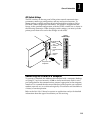
Front Panel Operation
The three light emitting diodes (LEDs) on the printer’s front panel (Power,
Alert, and Empty/Pause) indicate the conditions identified in the following
illustration:
Green LED
Orange LED
Yellow LED
Power
Alert
Empty/Pause
LED State
Indication
Off
On steady
Off
On flashing
On steady
Off
On flashing
On steady
Power off
Power on
Printing or idle
Over-temperature
System fault
Printing or idle
Paused
Media fault
Feed/Pause
3600M.004
Over-Temperature
If the printhead reaches an over-temperature condition, the Alert LED on the
printer flashes and the printer halts printing. Usually, you will not need to
intervene. If you allow the printer enough time to cool down, it normally
resumes operation on its own.
1-11
3600 Printer Maintenance Manual
c 3 9 frank
Media or System Faults
If you are servicing a printer indicating a media or system fault, refer to
Chapter 4, “Troubleshooting,” for information about the problem.
Feed/Pause Pushbutton
Operating the Feed/Pause button produces the following actions, depending
on what condition the printer is in:
Printer Condition
Operation/Function
If the printer is idle:
Pressing and releasing the Feed/Pause button
causes the printer to feed out one label or a
minimum specified amount of media.
Pressing and holding the button down causes
media to feed continuously until the button is
released.
Pressing the Feed/Pause button twice takes the
printer offline. Press the button once more to
bring the printer online.
If the printer is printing:
Pressing and releasing the Feed/Pause button
causes the printer to pause.
Subsequent pressing and releasing of the button
allows the printer to resume printing.
Pressing and holding the Feed/Pause button
down until the printer stops printing cancels the
current print job.
When the printer is first
powered on:
Pressing and holding the Feed/Pause button
down when turning printer power on places the
printer in the Test and Service mode and causes
the hardware configuration label to print.
Checking the Printer Configuration
The factory default settings for the 3600 printer are listed with the 3600
specifications in this chapter. These parameters are set using a combination of
DIP switch settings and downloadable printer commands, which are described
in the user’s manual. Remember, you can print out hardware and software
configuration labels for statistics of the printer you are servicing.
1-12
c 3 9 frank
General Information
1
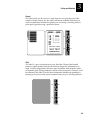
DIP Switch Settings
The DIP switches on the rear panel of the printer control communications
parameters, media type configuration, and test and service functions. To
change settings, carefully position the plastic (breakable) switches to ON or
OFF with a small straight-slot screwdriver. The printer is shipped from the
factory in the standard configuration, with the 16 DIP switches set as shown in
the following illustration. When changing switch settings, you must cycle the
printer power from off to on for the changes to take affect.
Factory
Default Settings
1
2
3
4
1 2 3 4 5 6 7 8
ON
8
1
ON/OFF
switch
7
I
6
Serial
communications
port
O
OFF
5
1 2 3 4 5 6 7 8
DIP
switches
2
3
4
ON
5
OFF
6
AC power cord
receptacle
7
8
3600M.005
Connecting the Printer to a Computer
To operate as intended, the 3600 must be interfaced with a computer (desktop
or laptop PC, local area network, AS400 or similar mainframe) with its serial
port configured for the communications protocol appropriate to the computer
interface. It is assumed that the correct interface (point-to-point, non-switched
modem, network, etc.) was achieved originally at installation and should have
a history of correct operation.
Refer to the 3600 User’s Manual or contact an applications analyst for detailed
information about the type of installation you are servicing.
1-13
3600 Printer Maintenance Manual
c 3 9 frank
Serial Port Settings
Parameter
Settings
Description
Baud Rate
1200, 2400, 4800, 9600,
19,200
The rate, in bits per second (bps) at
which the host exchanges data with
the printer.
Parity
Even, Odd, None
Checks each transmitted character for
errors.
Protocol
Intermec, XON/XOFF,
XON/XOFF with status
The type of network used to connect
the printer, the host, and the rest of
the data collection system. Intermec
protocol includes Standard, Polling
Mode D, and Multi-Drop protocols.
Device
Address
A to Z,
0 to 5
Unique address for each device
connected using Multi-Drop protocol.
Test and
Service
Test Prints, Data Line
Print, Cloning, Selective
Transfer, Memory Reset
Provides printer diagnostics to the
host and prints test labels.
Printing
Regardless of your computer setup, you can use several methods to download
information to print labels. This section describes different ways you can
communicate with the printer. Refer to the 3600 User’s Manual for detailed
information.
Note: Remember that these factors affect print quality: correct media, media sensitivity
setting, print speed, and correct bar code orientation.
Using Label Debut
If you are using a point-to-point (printer-to-PC) connection to communicate
with the printer, the printer parameters can be easily set using the DOS-based
software package Label Debut. The Label Debut prompting screens assist you
in designing, printing, and editing labels. Refer to the Label Debut User’s Manual
for more detailed information.
Using Third-Party Software
Your customer may be using third-party software to create label formats and
convert graphics into a UDC format that the 3600 printer can interpret. You can
use the same software to set the printer parameters.
1-14
c 3 9 frank
General Information
1
Using the Printer Command Set
You can also create labels by downloading formats (designs) and data created
with the printer command set. The commands in the printer command set can
perform any function or activate any feature of the 3600 printer. You can use
the following methods to download commands:
•
Downloading printer commands using DOS
•
Using ASCII control characters or hexadecimal equivalents
•
Using readable protocol/command characters
•
Downloading printer commands with a PC communications program or
host terminal
•
Using a Novell network
1-15
c 3 9 frank
2
Preventive Maintenance
Preventive Maintenance
2
This chapter identifies scheduled maintenance actions and provides illustrated
procedures for cleaning the 3600 printer.
Preventive Maintenance Actions and Intervals
Preventive maintenance consists primarily of scheduled cleanings, but also
occassional performance checks and, possibly, adjustments based on those
checks. When you perform preventive maintenance, you should also conduct
the tests and adjustments described in Chapter 3, “Testing and Adjusting,” that
will ensure the printer continues to deliver the highest quality output. You
need to perform preventive maintenance procedures at the intervals identified
to ensure a printer remains in proper working condition.
The following table is a schedule of recommended printer cleaning and
checking. Detailed cleaning procedures follow. Chapter 4, “Troubleshooting,”
contains instructions for performing various tests and adjustments.
Printer Component
Maintenance Action and Interval
Printer
Inspect the printer (and the rest of the data collection system) at every
service visit. Your inspection should include the types of items listed in the
following section.
Printhead
Inspect after every roll of media. Clean after every roll (or 6,000 inches) of
media or more often if necessary. Inspect or test print quality every service
visit. Make any necessary adjustments.
Drive roller and tear bar
Clean after every five rolls of media. Using hi-tack adhesive requires
cleaning after every roll of media. If the customer uses tag stock or
continuous media, you may want to clean after every five rolls of media,
or more often if necessary. Harsh or dusty environments dictate the need
to clean more frequently. Inspect or test the operation of these printer
elements at every service visit. Make any necessary adjustments.
Media path, edge, and
guides
TTR drive roller
Liner drive roller
Media supply post
Label and ribbon sensors
Pinch roller
2-3
3600 Printer Maintenance Manual
Inspecting the Printer
You should routinely inspect the printer and the rest of the data collection
system. Your inspection needs to address the following and similar concerns:
•
Make sure the printer is properly grounded.
•
Make sure the printer’s AC power source is within tolerance.
•
Make sure the printer is clean.
•
Make sure the printer is away from liquids.
•
Inspect the work environment for cleanliness and arrangement. Large
electric motors, welders, and switching equipment can negatively affect
printer performance.
•
Check the data collection network regularly for loose wires or poorly
installed connections. Be sure to replace corroded wires.
Cleaning the Printer
Use these procedures to access the printer parts and clean them. Heed the
warnings and cautions to prevent harm to yourself or damage to the printer.
You will need the following items to clean the printer correctly:
WARNING
2-4
•
Isopropyl alcohol
•
Cotton swabs
•
Clean lint-free cloth
•
Soft bristle brush
•
Vacuum cleaner
•
Soapy water/mild detergent
Warning
Energized electrical equipment is dangerous. Switch off the printer
power and remove the power cord before cleaning any part of the
printer. Failure to comply can result in injury or death.
Preventive Maintenance
2
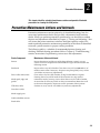
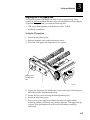
Removing the Media Cover
Most of the cleaning procedures require that you remove the media cover.
To remove the media cover
1. Place your fingers in the space at the lower center edge of the media cover
and pull the bottom of the cover away from the base of the printer.
2. Grasp the front of the media cover and lift the front of the cover upward.
3
2
Pow
er
Ale
rt
Em
pty
/P
au
se
Fe
ed
/P
au
se
Inte
rme
Media
cover
c
36
00
1
Media cover
release
(between the two
notches)
3600M.010
3. Lift the media cover away from the printer.
2-5
3600 Printer Maintenance Manual
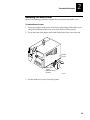
Cleaning the Printhead
Since the printhead must maintain close contact with the media to provide
good print quality, cleaning media debris from the printhead is very important.
Clean the printhead after every roll (or 6,000 inches) of media or whenever
necessary.
CAUTION
Caution
Do not use sharp objects such as knives or screwdrivers to scrape
the printhead clean. Cleaning with sharp objects will damage the
printhead. Clean with only a cotton swab, or a clean, lint-free cloth
or tissue moistened with isopropyl alcohol.
To clean the printhead
1. Remove the media cover.
2. Raise the printhead by rotating the head lift lever clockwise until the
printhead releases.
TTR/
ribbon
Media roll
Printhead
lift lever
3600M.011
2-6
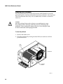
Preventive Maintenance
2
3. Remove the media from the paper path and the ribbon (if installed) from
the TTR supply and takeup hubs.
4. Use a cotton swab moistened with alcohol to remove any dirt, adhesive, or
debris from the print surface on the bottom of the printhead.
Po
we
r
Ale
rt
Em
pty
/P
au
se
Fe
ed
/P
au
se
Inte
rme
c
36
00
Thermal
printhead
3600M.012
5. Wait 5 to 10 seconds for the print surface to dry. Reload the media (and
ribbon if used).
6. Engage the printhead by rotating the head lift lever counterclockwise until
it locks in place.
7. If you are finished cleaning, install the media cover.
2-7
3600 Printer Maintenance Manual
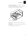
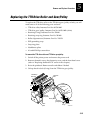
Cleaning the Rollers and Tear Bar
Cleaning the platen roller and the tear bar preserves print quality by ensuring
close contact between the media and the printhead. The TTR roller, liner roller,
and media roller are cleaned in the same fashion to minimize general debris
and to maximize their efficiency.
To clean the rollers and tear bar
1. Remove the media cover.
2. Raise the printhead by rotating the head lift lever clockwise until the
printhead releases.
3. Remove the media from the paper path and the ribbon (if installed) from
the TTR hubs.
4. Clean the rollers with a lint-free cloth moistened in isopropyl alcohol. Wipe
the cloth over the rollers, rotating each roller so that you clean all of it.
Media roll
roller
TTR
roller
Po
we
r
Ale
rt
Em
pty
/P
au
se
Fe
ed
/P
au
se
Inte
rme
c
36
00
Platen
roller
Tear
bar
Liner
roller
3600M.013
5. Clean both sides of the tear bar with a lint-free cloth moistened in isopropyl
alcohol. Remove all traces of dust, paper, and adhesive.
6. Reload the media (and ribbon if used) and then engage the printhead by
turning the head lift lever counterclockwise until the printhead locks.
7. If you are finished cleaning, install the media cover.
2-8
Preventive Maintenance
2
Cleaning the Media Guides and Media Path
Clean the media guides and media path regularly to keep debris off the media
surface and printhead where irregularities can spoil print quality or damage
the printhead. Cleaning the guides also helps prevent media skewing or
improper tracking as it travels through the paper path, which can result in
print problems. Always clean the media guides immediately after any label jam
in the printer.
Media debris may accumulate around the printer mechanism and along the
media path during normal operation of the printer. Clean debris away using a
soft bristle brush or vacuum cleaner. Remove all traces of dust, paper, and
adhesive. Clean the flat surfaces of the media path (including the edge guide)
with a lint-free cloth and isopropyl alcohol. Also remove all traces of dust,
paper, and adhesive from the pinch rollers on the media access door.
To clean the media guides and media path
1. Remove the media cover.
2. Remove the media from the paper path and the ribbon (if installed) from
the TTR hubs.
3. Pull down and hold the spring-loaded lower media guide to open up the
media path.
4. Clean the lower media guide with a lint-free cloth moistened in isopropyl
alcohol.
Po
we
r
Ale
rt
Em
pty
/P
au
se
Fe
ed
/P
au
se
Inte
rme
c
36
00
Upper media
guide
Lower media
guide
Media
path
3600M.014
2-9
3600 Printer Maintenance Manual
5. Use a lint-free cloth moistened with isopropyl alcohol to clean the upper
media guide. Be sure to remove all traces of debris.
6. Reload the media (and ribbon if used).
7. If you are finished cleaning, install the media cover.
To clean the pinch rollers
1. Open the media access door.
2. Use a cotton swab moistened with isopropyl alcohol to clean the pinch
rollers. Rotate the rollers to get any debris out of all of the grooves.
Po
we
r
Ale
rt
Em
pty
/P
au
se
Fe
ed
/P
au
se
Inte
rme
c
36
00
Pinch
Roller
Media
access
door
3600M.015
3. If you are finished cleaning, install the media cover.
2-10
Preventive Maintenance
2
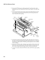
Cleaning the Label and Ribbon Sensors
There are three label sensors and a ribbon sensor on the 3600 printer that
require cleaning: the label taken sensor, the label mark sensor, the label gap
sensor, and the ribbon motion sensor.
To clean the sensors
1. Remove the media cover.
2. Raise the printhead by rotating the head lift lever clockwise until the
printhead releases.
3. Remove the media from the paper path and the ribbon (if installed) from
the TTR hubs.
4. Clean the label taken sensor and the label mark sensor with a cotton swab
moistened with isopropyl alcohol.
Ribbon
motion
sensor
Cotton
swab
Encoder
decal
Main PCB
Label taken
sensor
Label mark
sensor
Drive
roller
Upper media
guide
(underside)
Cleaning
brush
Lower
media guide
Label gap
sensor
3600M.016
2-11
3600 Printer Maintenance Manual
5. Pull down on the lower media guide to expose the label gap sensor. Using
a soft bristle brush, remove all debris and dust from the label gap sensor.
6. Clean the label gap sensor with a cotton swab and alcohol.
7. Remove the electronics cover.
8. Very carefully clean the small ribbon motion optical sensor on the main
PCB and the black and white encoder decal on the TTR supply
clutch/encoder assembly with a cotton swab moistened with alcohol.
9. Install the electronics cover.
10. Reload the media (and ribbon if used).
11. Engage the printhead by rotating the head lift lever counterclockwise until
it locks in place.
12. If you are finished cleaning, install the media cover.
Cleaning the Printer Covers
Clean the 3600 printer covers with a general purpose cleaner (soapy
water/mild detergent). Do not use abrasive cleansers or solvents. Be sure to
clean the transparent panel on the media cover so that you can see the media
supply inside the printer when the cover is closed.
2-12
3
Testing and Adjusting
c 3 9 frank
Testing and Adjusting
3
This chapter contains procedures for testing the printer’s performance as a quality
check during preventive maintenance, as a functional check when troubleshooting,
and as part of the repair process after replacing a printer component. This chapter
also contains procedures for making adjustments and alignments that ensure the
printer is operating normally.
Testing the Printer
If you are on site for preventive maintenance or are following up a corrective
action and the printer is working, start conducting quality checks from the Test
and Service mode. If you are on site for corrective maintenance, determine if
the problem lies with setup and process or the printer itself. Use the Test and
Service mode to determine if the printer can print. If it can, perform the
communications test.
The quality and efficiency of producing labels reveals if a printer is operating
correctly. In addition to analyzing labels to evaluate printer performance, the
3600 printer Test and Service mode allows you to conduct printer tests that
include printing test labels (illustrated in this section) with a fixed look so you
can compare them to an expected standard. The test labels can be used for
checking printhead alignment, printhead bias, dots out of specification, label
tracking, and ribbon wrinkling. Test and Service mode functions can be run at
the printer or from a host terminal through the use of commands.
If you find a printer lacking in performance after running your tests, check and
make the adjustments and alignments necessary to return the printer to normal
service. If you cannot get a printer working properly with an adjustment or
alignment, troubleshoot for a component failure.
Note: Making the alignments out of order can introduce, not solve printing problems.
Review the section about printer alignments before making any changes.
3-3
3600 Printer Maintenance Manual
c 3 9 frank
Running Test and Service Mode at the Printer
Note: When the printer is placed in Test and Service mode, it prints out a hardware
configuration label, regardless of its initial DIP switch settings, and remains in Test
and Service mode until the power is switched off and the DIP switches are reset.
Momentarily pressing the Feed/Pause button during a test will cause the test to halt.
Holding the Feed/Pause button down will start a new run of whichever test you select.
To enter Test and Service mode and select test functions at the printer
1. Switch off the printer power.
2. Set the DIP switches to select the function that you want to run.
3. Press down and hold the Feed/Pause button while powering on the
printer. The printer prints out a hardware configuration label.
4. Hold the Feed/Pause button down for 1 second. The test begins
immediately.
5. If you wish to perform another function, repeat Steps 1 through 4. The
function currently being executed is terminated and the new function
begins.
To exit Test and Service mode
1. Switch off the printer power.
2. Return all DIP switches to their original settings.
3. Switch on the printer power.
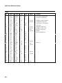
Setting DIP Switches
Use the information provided in the following tables and examples to set the
DIP switches for the Test and Service mode function that you wish to perform.
The “0”s indicate that the switch is in the OFF position and the “1”s indicate
that the switch is in the ON position.
3-4
c 3 9 frank
Testing and Adjusting
3
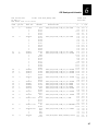
Test and Service Switch Settings
Top Bank
O = OFF
1 = ON
OFF
TESTS
ON
Test Prints
Configurations
Hardware
Software
Test Labels
Print Quality
Pitch
Page
Single Page
All Pages
Format
Single Format
All Formats
UDC
Single UDC
All UDCs
Font
Single Font
All Fonts
Data Line Print
1
2
3
4
5
6
Bottom Bank
7
8
1
2
3
4
5
6
7
8
O O O O O O O O
O O O O O O 1 O
O O
O O
O O O O O A
O O O O O A
O O O 1
O O O 1
O O O O
O O 1 O
O O
O O
O O O O O A
O O O O O A
O O O O 1 O O O
O O O 1 O 1 1 O
B B
1 1
B B B O O A
1 1 1 O O A
O O O 1
O O O 1
B B
1 1
B B B O O A
1 1 1 O O A
1
1
O O O
O 1 O
O O O O O 1
O O O O O 1
O O
1 O
B B
1 1
B B B B B
1 1 1 1 1
O O O 1
O O O 1
O O
1 O
B B
1 1
B B B B O O
1 1 1 1 O O
O O O O O O O
O O
O O O O O O
1
O 1
O 1
A
A
Cloning
Receiver
Sender
Selective Transfer
Receiver
Send Pages
Single Page
All Pages
Send Format
Single Format
All Formats
Send UDC
Single UDC
All UDCs
Send Font
Single Font
All Fonts
Send Configuration
Send Tables
Send All
Memory Reset
Page/Format
UDC/Font
Configuration
Tables
All
O 1
O 1
O O O O O O
O 1 O O O O
O O
O O
O O O O O O
O O O O O O
1
1
O O O O O O
O O
O O O O O O
1
1
1
1
O 1
O 1
C C
1 1
C D D D D D
1 1 1 1 1 1
1
1
1
1
O O 1
O O 1
O O O
O 1 1
O O
1 1
O D D D D D
1 1 1 1 1 1
1
1
1
1
O 1
O 1
1
1
O C C
O 1 1
C C
1 1
C C C C O O
1 1 1 1 O O
1
1
1
1
1
1
1
1
1
1
O
O
O
O
O
O
O
1
O
1
O
O
O
1
1
1
1
1
1
1
C
1
O
O
O
C
1
O
O
O
C
1
O
O
O
C
1
O
O
O
C
1
O
O
O
D
1
O
O
O
D
1
O
O
O
D
1
O
O
O
D
1
O
O
O
O
1
O
O
O
O
O
O
O
O
O
O
O
O
O
1
1
1
1
1
O
1
O
1
1
O
O
1
O
1
O
O
O
O
1
O
O
O
O
O
O
O
O
O
O
O
O
O
O
O
O
O
O
O
O
O
O
O
O
O
O
O
O
O
O
O
O
O
O
O
O
O
O
O
O
O
O
O
O
O
O
O
O
O
O
O O C C
O O 1 1
A: OFF = Batch of 1. ON = Batch of 100.
B: Page/Format/UDC/Font number. Least significant bit first.
C: Source Page/Format/UDC/Font number. Least significant bit first.
D: Destination Page/Format/UDC/Font number. Least significant bit first.
3600M.020
3-5
3600 Printer Maintenance Manual
c 3 9 frank
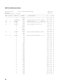
Test and Service Configuration Settings
Top Bank
Bottom Bank
OFF
O = OFF
1 = ON
ON
1
2
3
Label Rest Point
Adjust Forward
Adjust Backward
O
1
1
86XX Emulation
Advanced Mode
10 Mil
15 Mil
1
X Forms Adjust
Adjust Forward
Adjust Backward
1
Y Forms Adjust
1
4
5
6
7
8
1
3
4
5
6
7
8
N N N N N
N N N N N
O
1
O
2
1
O O
1 O
1 1
1
1
1
N N N N N
N N N N N
O
1
1
N N N N N
1 O
N: Number. Least significant bit first.
3600M.021
Dot Increment Switch Settings
Bottom Bank
OFF
0 = OFF
1 = ON
ON
1
2
3
4
5
1
O
1
O
1
O
1
O
1
O
1
O
1
O
1
O
1
O
1
O
1
O
1
O
1
O
1
O
1
O
O
1
1
O
O
1
1
O
O
1
1
O
O
1
1
O
O
1
1
O
O
1
1
O
O
1
1
O
O
1
O
O
O
1
1
1
1
O
O
O
O
1
1
1
1
O
O
O
O
1
1
1
1
O
O
O
O
1
1
1
O
O
O
O
O
O
O
1
1
1
1
1
1
1
1
O
O
O
O
O
O
O
O
1
1
1
1
1
1
1
O
O
O
O
O
O
O
O
O
O
O
O
O
O
O
1
1
1
1
1
1
1
1
1
1
1
1
1
1
1
# of dot increments
1
2
3
4
5
6
7
8
9
10
11
12
13
14
15
16
17
18
19
20
21
22
23
24
25
26
27
28
29
30
3600M.022
3-6
c 3 9 frank
Testing and Adjusting
3
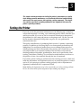
Printing Test Labels
The test labels can be used for checking printhead alignment, printhead bias,
dots out of specification, label tracking, and ribbon wrinkling. The examples
show the DIP switch settings that select the illustrated label.
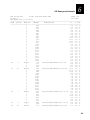
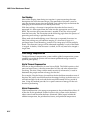
Hardware Configuration
The hardware configuration label is the first label printed when you enter Test
and Service mode. This label serves as a configuration reference as well as an
alphanumeric and alignment print test. This label contains the following
information and uses:
•
Printer memory including both storage and image RAM.
•
Printer mileage including inches processed and inches burned.
•
Printhead settings including width, dot size, and burn pot setting.
•
Firmware checksum, program, and version number.
•
Vertical lines for evaluating printhead alignment.
To achieve the highest quality label, print the hardware configuration label at a
speed of 3 ips (inches per second).
1
3600 Hardware Configuration
2
3
ON
OFF
5
: 128 kilobytes
: 382 kilobytes
: none
4
: 540
: 204
:0
6
7
8
: 1344 dots
: 5.0 mil
: 213
1
2
: none
: none
: Self Strip
3
4
ON
OFF
6
: FAC3
: OC3E
: 062198
: 1.1
5
Memory Installed
Storage RAM
Image RAM
Flash RAM
Mileage
Inches Processed
Inches Burned
Labels Cut
Printhead
Width
Dot Size
Burn Pot Setting
Hardware Options
I/O Option
Internal Option
External Option
Firmware Checksum
ROMO (U9)
ROM1 (U8)
Program
Version
7
8
3600M.023
3-7
3600 Printer Maintenance Manual
c 3 9 frank
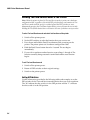
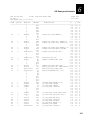
Software Configuration
This three-label set lists current configuration parameters that are set from the
host computer. It also lists defined pages, formats, graphics, fonts, and
installed options. This label serves as a configuration reference as well as an
alphanumeric and multiple label alignment and print test.
1
2
PRINT SPEED - 3.0 IPS
RIBBON SAVE - Disabled
BAUD RATE - 9600
0
IMAGE BANDS - 3
SELF STRIP - Disabled
DATA BITS - 7
Formats Defined :
0, 19
MAX LABEL LENGTH - 4 inches CUTTER - Disabled
MESSAGE LENGTH - 255
Fonts Defined :
0, 1, 2, 7, 20 21, 22, 23, 24,
25, 30, 31, 32, 33, 34, 35, 36,
37, 38, 39, 40, 41
LABEL STOCK - Inter- label gap DARK ADJUST - 0
PARITY - Even
MEDIA TYPE - Direct Thermal
X FORMS ADUST - 0
STOP BITS - 1
MEDIA LENGTH - 0 inches
Y FORMS ADJUST - 10
PROTOCOL - Xon/Xoff No Status
CHARACTER SET - US ASCII
LABEL REST POINT - 0
DEVICE ADDRESS - A
TRANSLATION - Disabled
SENSITIVITY - 420
INTERNAL OPTIONS - none
4
1.1
Pages Defined :
3
Program Version :
ON
OFF
5
6
7
8
Graphics Defined : none
1
3
4
EXTERNAL OPTIONS - Self Strip
2
EMULATION - Disabled
ON
OFF
5
LABEL RETRACT - Enabled
6
7
8
3600M.024
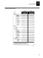
Print Quality
This label contains bar codes and human readable fields that you can use to
determine whether the printer you are testing is attaining the best print quality
possible. If you notice problems with the print quality, check and perform the
adjustment and alignment procedures provided in this chapter to achieve
optimum printer performance.
1
CODE,39,3.0./1
2
3
MODEL
3600
CODE 39 3.0 /1
4
OFF
5
CODE,39,3.0./1
Prog 062198
Version 1.1
ON
6
CODE 39
2.5 / 1
7
8
1
2
3
Everett, WA 98203
4
5
*SUPPLIER*
*SUPPLIER*
6
7
*PICKETFIELD*
*PICKET FIELD*
*PICKETFIELD*
*PICKETFIELD*
*PICKET FIELD*
INTERMEC
INTERMEC Corporation
CODE 39
3.0 / 1
CODE 39
*PICKET FIELD*
ON
8
3600M.025
3-8
OFF
c 3 9 frank
Testing and Adjusting
3
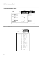
Format
This label, which can be a test of a single format or can provide a two-label
sample of all the formats, has bar codes and human-readable fields that you
can use to determine whether the printer you are testing is attaining the best
print quality possible using a particular format.
CODE,39
0123456789
CODE 39
3600 TEST LABEL
3600 TEST LABEL
3600 TEST LABEL
8
3600 TEST LABEL
OFF
7
CODE,39
3600 TEST LABEL
CODE 39
6
1
3600 TEST LABEL
2
1234
5670
ON
5
0123456789
4
CODE,39
0123456789
3
CODE 39
2
*
1
OOOOOOOOOOOOOOOOOO
*
3
3600 TEST LABEL
4
ON
5
3600 TEST
OFF
6
CODE,93,TEST,PRINT,BARCODE
7
CODE,93,TEST,PRINT,BARCODE
8
DT / TTR PRINT QUALITY SAMPLE
3600M.026
Pitch
This label is a gray scale printout of every third dot. The test label should
present a regular pattern with dots that line up diagonally when held at an
angle. Look for irregularities that may signal a problem with the platen roller
or the media path. If the printhead is uneven or the print path is skewed, it will
be reflected in this label. Use this label to determine whether the printhead is
printing evenly, but use the actual customer format to pass/fail the printhead.
1
2
3
4
ON
OFF
5
6
7
8
1
2
3
4
ON
5
OFF
6
7
8
3600M.027
3-9
3600 Printer Maintenance Manual
c 3 9 frank
Font
This is a multiple-label test of the available fonts. You can test a single font
(Font 20 shown) or all of the fonts. An all-font test will use a lot of media. It is
better that you test one font at a time to make your determinations.
1
Á
}
D
Å
È
Ì
193 197 201 205
ON
OFF
6
_
Â
26 130 134 138 142
Æ
Ç
Ë
Ï
95 199 203 207
2
7 131 135 139 143 14
Î
1
Â
3 7 11 15 19 23
Ê
194 198 202 206
8
2 6 10 14 18 2
7
FONT 20
125 129 133 137 141
Ë
5
1 5 9 13 17 2
A
192 196 200 204
4
124 128 132 136 140
3
12 16 2
2
Á
|
0 4 8
3
4
ON
5
OFF
6
7
8
3600M.028
Page
These labels test the ability to download and correctly print single or multiple
pages (a group of labels always printed together) of label data from a host. The
data can be yours or the customer’s, but you should include a test of the
customer’s labels to determine whether the printer you are testing is attaining
the best print quality possible with the customer’s data.
UDC
This label tests the ability to download and correctly print single or multiple
user-defined characters (bitmap graphic) from a host. The data can be yours or
the customer’s, but you should include a test of the customer’s labels to
determine whether the printer you are testing is attaining the best print quality
possible with the customer’s data.
3-10
c 3 9 frank
Testing and Adjusting
3
Running Test and Service Mode From a Host Computer
When conducting Test and Service mode functions from a computer, hardware
diagnostic information is uploaded to the host from the printer.
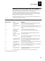
The following table describes the commands you would issue from a host
terminal to run the Test and Service mode. To select Test and Service mode
from Print mode, send <ESC>T from the host terminal.
Note: All commands in Test and Service mode end with the command terminator (;),
except the last command in a message.
Test and Service Mode Command Descriptions
Command Code
Test
Description
A
Transmit Ambient
Temperature*
Transmits the ambient temperature sensor output back to
the host. The value ranges from 00 to FF.
B
Printhead Resistance
Test*
Causes the printer to begin the printhead resistance test. The
printer will respond with the ASCII character string “pass”
or “fail.”
C
Print Pitch Label
Causes the printer to print the pitch label.
D
Reset Printer
Configuration
Sets the printer configuration to the factory defaults.
G
Transmit
Transmissive Sensor
Value
Transmits the label gap output back to the host. Values
ranges from 00 to FF.
K
Dark Adjust*
This command changes the darkness of the print on your
labels. It is for fine-tuning only.
L
Transmit Paper Path
Open Sensor Value*
Transmits the Paper Path Open switch value back to the
host. A value of 0 indicates the paper path is open and a
value of 1 means it is closed.
M
Transmit Reflective
Sensor Value
Transmits the label mark reflective sensor output back to the
host. The values range from 00 to FF.
P
Transmit Printhead
Temperature Sensor
Value
Transmits the Printhead Temperature Sensor output back to
the host. Values range from 00 to FF.
Q
Print Quality Label
Causes the printer to print out the print quality program
and model number label.
R
Exit Test and Service
Causes the printer to exit Test and Service mode.
* The printer ignores this command.
3-11
3600 Printer Maintenance Manual
c 3 9 frank
Test and Service Mode Command Descriptions (continued)
Command Code
Test
Description
S
Transmit Printhead
Resistance Values*
Transmits the average, maximum, or minimum printhead
dot resistance value back to the host. Each value is a
numeric data string separated by a comma.
T
Transmit Label
Taken Sensor Value
Transmits the label taken sensor output back to the host.
Values can range from 00 to FF.
U
Transmit 40V Supply
Value*
Transmits the 12V supply output back to the host. The
values range from 00 to FF.
V
Transmit 24V Supply
Value*
Transmits the 24V supply output back to the host. Values
can range from 00 to FF.
* The printer ignores this command.
Testing Printer and Host Communications
This is a simple test of host-to-printer communications. If this test fails, there
may be a problem with the printer serial port receiver circuitry or the setup.
To test host-to-printer communications
1. Switch the printer power off. Return the DIP switch settings to the standard
configuration if they have been changed.
2. Press and hold the Feed/Pause button while powering on the printer. The
printer presents the hardware configuration test label.
3. Release the Feed/Pause button after the hardware configuration label is
printed. You are now in data line print mode within the Test and Service
mode.
4. Send down some characters from the host. At this point the printer does
not attempt to interpret any printer commands, but simply prints each
character and its hexadecimal equivalent as it is received. If you are using a
PC running DOS, send down the following strings of commands from the
DOS prompt:
Note: ^Z is [Ctrl] [Z].
\MODE COM1: 96,E,7,1,N [Enter]
(to configure the serial port)
\COPY CON COM1: [Enter]
(tells the PC to copy the following text to the COM1 port)
ABCDEF^Z [Enter]
(these characters are sent to the printer)
3-12
c 3 9 frank
Testing and Adjusting
3
5. A good test will result in the following printout :
3600M.029
6. To enter normal print mode again, switch the printer power off and then on
again.
If this test does not work, recheck after you make sure that the DIP switches
are set to the default configuration and that the printer cable is securely
plugged into COM1 of your PC.
Note: If you are using a different platform to communicate with your printer, refer to
your host computer user’s manual and the 3600 Bar Code Printer User’s Manual
for more detailed information about downloading commands.
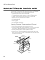
Adjusting the Printer
The following procedures provide instructions for adjusting the print bias, the
print intensity (darkness), the label mark sensor, the label gap sensor, the label
taken sensor, and the printhead fine adjustment lever on the 3600 printer.
WARNING
CAUTION
Warning
Always disconnect the power cord before removing the electronics
cover unless a procedure requires the unit to be energized. Failure to
disconnect the power cord may result in injury or death due to
electric shock.
Caution
The printhead and integrated circuits on printer circuit boards in
this equipment are sensitive to damage by electrostatic discharge
(ESD). Prevent ESD by always wearing skin contact ground straps
firmly attached to the equipment metal base assembly when
working inside of the equipment housing. Failure to comply can
result in damage to components or the printhead.
3-13
3600 Printer Maintenance Manual
c 3 9 frank
Adjusting the Print Bias for Print Quality
Adjust the bias with a straight-slot screwdriver if the printhead is not making
even contact with the media. Using different width media, especially narrow
media, can result in uneven contact or a spot where there is no media between
the printhead and the platen roller. Extra wear and damage can occur if narrow
media is used for extended periods with incorrect bias.
To adjust the bias adjust screw
1. Remove the media cover and locate the bias adjust screw.
Printhead bias
adjust screw
Po
we
r
Al
er
t
Em
pt
y/
Pa
us
e
Fe
ed
/P
au
se
Inte
rmec
36
00
3600M.030
2. Turn the bias adjust screw counterclockwise to compensate for light print
on the right side of the label; turn the bias adjust screw clockwise to
compensate for light print on the left side.
If printing is light on
the left side of label,
turn the bias adjust screw
clockwise.
N*
RA
OR
LW
*E
*N
AR
RO
WL
E*
If printing is light on
the right side of label,
turn the bias adjust screw
counterclockwise.
3600M.031
3. Install the media cover.
3-14
c 3 9 frank
Testing and Adjusting
3
Adjusting the Print Intensity
Note: Before you adjust print intensity, verify the sensitivity rating for the media
matches the rating set in the printer.
Use the darkness adjust control in combination with the darkness adjust
command <SI>d to fine-tune the intensity of print on your customer’s labels.
The fine adjustments compensate for variations in the media (“lot to lot”), the
printhead, or the printer. Set the darkness adjust control with a small straightslot screwdriver after entering the proper sensitivity number.
To adjust the print darkness control
1. Locate the darkness adjust control on the back of the printer. Make
adjustments with a small straight-slot screwdriver.
1 2 3 4 5 6 7 8
Turn the darkness
adjust control clockwise
for darker density. Darkness
adjust control
1 2 3 4 5 6 7 8
I
1 2 3 4 5 6 7 8
O
Turn the darkness adjust
control counterclockwise
for lighter density.
1 2 3 4 5 6 7 8
Screwdriver
3600M.032
2. Increase the darkness by turning the darkness adjust control clockwise or
decrease the darkness by turning the control counterclockwise. Run a test
print to evaluate the print quality.
3-15
3600 Printer Maintenance Manual
c 3 9 frank
Adjusting the Printhead Adjustment Lever for Print Quality
The printhead adjustment lever is located at the end of the printhead pivot
bracket. It allows fine-tuning of the printhead fore/aft position. The printhead
adjustment lever provides three stops forward movement of the printhead and
three stops backward movement from center position in 0.006-inch increments.
To achieve the best print quality, raise the printhead with the printhead lift
lever and position the printhead adjustment lever as shown in the illustration:
from the rear, adjust clockwise/left to move the printhead forward, or adjust
counterclockwise/right to move the printhead backward.
1 2 3 4 5 6 7 8
1 2 3 4 5 6 7 8
I
O
d
ea
Printhead
adjustment
lever
th
rin
p
s
ve rd
mo kwa
c
ba
ad
the rd
n
i
r
a
s p rw
ve fo
mo
3600M.033
3-16
c 3 9 frank
Testing and Adjusting
3
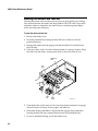
Adjusting the Label Mark Sensor
The mark sensor detects the mark on the back of continuous media stock. The
output is then used to determine the start of print point. This sensor is located
under the label pathway across from the platen roller. Two adjustments affect
the performance of this sensor, its physical position and sensitivity. To perform
this procedure, you need the following tools:
•
Digital multimeter
•
#2 Phillips screwdriver
•
Small straight-slot screwdriver
To position the label mark sensor
1. Remove the media cover.
2. Use your finger to reach underneath the lower guide.
Platen
roller
Locate the label mark sensor
behind the platen roller near
the inboard edge of the printer.
Use your index finger to adjust
the label mark sensor.
Inboard edge
of printer.
The platen roller
is not shown
for clarity only.
Label mark
sensor
3600M.034
3-17
3600 Printer Maintenance Manual
c 3 9 frank
3. Slide the mark sensor into a position that centers it over the label mark as
the media passes by. It is adjustable from the inboard edge of the extrusion
to one half of the paper path width toward the outboard edge.
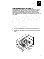
To adjust the label mark sensor potentiometer sensitivity
1. Remove the electronics cover
2. Switch on the printer power.
3. Enable the printer for mark sensing using the <SI>T{2} command.
4. Connect the positive lead of a digital voltmeter to TP18 (MARK) and the
negative end to TP14 (GND) on the main PCB.
TP18
TP14
R191
3600M.035
5. Place the white portion of a label under the mark sensor.
6. Adjust R191 on the main PCB so the voltage at TP18 is 1V ± 0.2V.
7. Place the black mark portion of the label under the mark sensor.
8. The voltage at TP18 should now be greater than 2.5V.
9. Install the printer electronics cover and the media cover.
10. Check the printer for proper operation.
3-18
c 3 9 frank
Testing and Adjusting
3
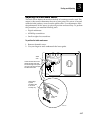
Adjusting the Label Gap Sensor
The label gap sensor output enables the software to determine the leading edge
of a label by detecting the label gap. The label gap is the space between labels
on the backing material. This reading enables the printer to properly position
the start of print point. To perform this procedure, you need the following
tools:
•
Digital multimeter
•
#2 Phillips screwdriver
•
Small straight-slot screwdriver
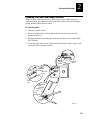
To adjust the label gap sensor potentiometer
1. Remove the media cover and the electronics cover.
2. Connect the positive lead of a multimeter to TP15 (GAP) and the negative
lead to TP14 (GND) on the main PCB.
TP15
TP14
R124
3600M.036
3. Switch on the printer power.
4. Insert the label backing only in the label gap sensor. Adjust R124 on the
main PCB so that the voltage at TP15 (GAP) is 1V ± 0.2V.
5. Insert both the label and the label backing in the sensor. Verify that the
voltage at TP15 (GAP) is greater than 3V.
6. Install the printer electronics cover and the media cover.
7. Check the printer for proper operation.
3-19
3600 Printer Maintenance Manual
c 3 9 frank
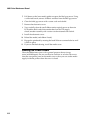
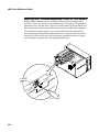
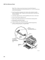
Adjusting the Label Taken Sensor
The label taken sensor output enables the software to determine that a label has
been taken by detecting the label’s presence. To perform this procedure, you
need the following tools:
•
Digital multimeter
•
#2 Phillips screwdriver
•
Small straight-slot screwdriver
To adjust the label taken sensor
1. Remove the media cover and the electronics cover.
2. Connect the positive lead of a multimeter to TP19 (TAKEN) and the
negative lead to TP14 (GND) on the main PCB.
R190
TP19
TP14
3600M.037
3. Switch on the printer power.
4. Feed one label out of the printer so that it rests under the label taken sensor
in a correct orientation.
5. Adjust R190 on the main PCB until the voltage at TP19 is 1.2V + 0.2V.
6. Remove the label from under the label taken sensor.
7. The multimeter reading at TP19 should now read above 4.5V.
8. Install the printer electronics cover and the media cover.
9. Check the printer for proper operation.
3-20
c 3 9 frank
Testing and Adjusting
3
Aligning the Printer
The following procedures provide instructions for aligning the rollers, aligning
the printhead, and aligning the ribbon supply hub on the 3600 printer.
Note: These alignments should be made in the sequence given. Performing them out of
order can introduce and not solve printing problems.
WARNING
CAUTION
CAUTION
Warning
Always disconnect the power cord before removing the electronics
cover unless a procedure requires the unit be energized. Failure to
disconnect the power cord may result in injury or death due to
electric shock.
Caution
Integrated circuits on printer circuit boards in this equipment are
sensitive to damage by electrostatic discharge (ESD). Prevent ESD
by always wearing skin contact ground straps firmly attached to
the equipment metal base assembly when working inside of the
equipment housing. Failure to comply can result in damage to
components.
Caution
Align only one outboard plate at a time (either upper or lower) to
put the rollers back into factory alignment. If both plates are
loosened, it may not be possible to align the rollers outside of the
factory.
3-21
3600 Printer Maintenance Manual
c 3 9 frank
Aligning the Rollers
You should perform this procedure every time an outboard plate is removed or
replaced. To perform this procedure, you need the following tools:
Note: If the printer you are servicing has upper outboard plate Intermec Part No.
062476-002 installed, you need to replace it with a new upper outboard plate Intermec
Part No. 063225-001 before you can perform the following roller alignment.
•
Roller alignment tool, Intermec Part No. T43150
•
#2 Phillips screwdriver
To align the rollers
1. Switch off the printer power and remove the power cord.
2. Remove the media cover, the electronics cover, and the front bezel cover
(refer to Chapter 5, “Remove and Replace Procedures,”for detailed
instructions).
3. Raise the printhead with the printhead lift lever. Remove media and ribbon
if loaded.
4. Loosen the Phillips screws on the outboard plate that you are aligning.
Note: Align only one outboard plate at a time (either the upper or the lower) to put
the rollers back into factory alignment. If both plates are loosened, it may not be
possible to align the rollers outside of the factory.
→
5. Align the three holes in the roller alignment tool with the platen roller, the
liner roller, and the TTR roller. The fourth hole in the roller alignment tool
fits over the black plastic cap closest to the front of the printer.
UP
3600M.038
3-22
c 3 9 frank
Testing and Adjusting
3
6. When the tool fits properly on all of the rollers and the bushing, tighten the
screws on the outboard plate that you are aligning.
7. Reattach the front bezel cover. Ensure that the media access door operates
properly (snaps firmly shut) after the front bezel cover is installed.
8. Install the electronics cover.
9. Reload media (and ribbon if used).
10. Install the media cover and the power cord.
11. Switch on printer power and check for proper operation.
Aligning the Printhead
Align the printhead only if necessary. To perform this procedure, you need the
following tools:
•
Printhead alignment tool, Intermec Part No. T43099
•
9/64-inch Allen screwdriver
To align the printhead
1. Switch off the printer power. Remove the power cord and the media cover.
2. Raise the printhead with the printhead lift lever. Remove media and ribbon.
3. Position the printhead adjustment lever clockwise/left two clicks during
the printhead alignment. Loosen the two Allen screws located on the
printhead yoke at the back of the printhead heatsink.
1 2 3 4 5 6 7 8
1 2 3 4 5 6 7 8
I
O
ad
he
Printhead
adjustment
lever
nt
pri
es rd
v
mo kwa
c
ba
ad
the
rin ward
p
r
s
ve fo
mo
3600M.039
3-23
3600 Printer Maintenance Manual
c 3 9 frank
Note: This is a change in procedure from previous printhead alignment
instructions that directed the printhead adjustment lever to be in the neutral/center
position during alignment.
4. Install the printhead alignment tool and press the printhead assembly
down on the platen roller. Align the tool with the notches in the heat sink
and the printhead.
5. Alternately tighten the two 9/64 inch printhead yoke screws until secure.
6. Remove the printhead alignment tool.
7. Return the printhead adjustment lever to the neutral/center position.
8. Reload media (and ribbon if used).
9. Install the media cover and the power cord.
10. Switch on printer power and test for proper printhead alignment by
printing out the print quality and pitch labels.
Guide pin
(Align with the notches
on the heatsink and printhead.)
Heatsink
Notch
Place the cutouts
of the printhead
alignment tool onto
the shaft of the platen
roller.
Printhead
alignment
tool
Po
we
r
Ale
rt
Em
pty
/P
au
se
Fe
ed
/P
au
se
Inte
rme
c
36
00
Printhead
alignment
tool
Printhead
lift lever
3600M.040
3-24
c 3 9 frank
Testing and Adjusting
3
Aligning the TTR Supply Hub
You should align the TTR supply hub only if you are experiencing ribbon
wrinkle on full width ribbon after the rollers and printhead have been aligned.
To perform this procedure, you need the following tools:
•
TTR supply hub alignment tool, Intermec Part No. T43149
•
#2 Phillips screwdriver
To align the TTR supply hub
1. Switch off the printer power.
2. Remove the media cover and the electronics cover.
3. Install the TTR supply hub alignment tool as shown.
Ribbon supply
hub alignment
tool
3600M.041
4. Tighten the alignment tool thumbscrew so the bushing tab is flush against
the bushing on the hub adjustment plate.
5. Loosen the two screws securing the hub adjustment plate.
6. Switch on the printer power.
7. Print a series of the same kind of labels that were having the ribbon
wrinkling problem. While they are printing, adjust the TTR supply hub up
or down (with the thumbscrew on the tool) until ribbon wrinkling is
eliminated.
3-25
3600 Printer Maintenance Manual
c 3 9 frank
Note: If this adjustment does not eliminate ribbon wrinkling, try readjusting the
ribbon supply hub and realigning the printhead.
8. When an alignment is achieved that eliminates the ribbon wrinkling,
tighten the two screws on the hub adjustment plate.
9. Remove the tool and retest for ribbon wrinkling.
10. After the printer is correctly adjusted, switch off the power and reattach the
electronics and media covers.
3-26
4
Troubleshooting
Troubleshooting
4
This chapter provides you with information that will help you determine why a printer
may not be working and how to get it working again.
About Troubleshooting and Repair
Use the information in this chapter to identify the cause of a failing printer. It is
assumed that a printer is not working and that the troubleshooting actions
referenced in the user’s manual were not used, failed to clear the problem, or
pointed to a printer malfunction.
Troubleshooting Tips
One of your first concerns is to duplicate and isolate the problem, to confirm if
the problem is the printer or not. Usually the printer was already working at
some point before you were called, so start with the last time it worked and
move forward logically, considering what might have changed since then. Do
not neglect to check simple things like, “Is the printer plugged in? Is there
power at the outlet? Are all of the connections good?” Spend a minute visually
examining the unit and considering the situation to see if anything obvious
stands out.
Where to Start
If you have not already done so, review the user’s troubleshooting information
in this chapter and use tests from Chapter 3, ”Testing and Adjusting,” to
determine if and how the printer performs offline. If you have a working
installation at hand, consider the value and difficulties of trying the printer in a
known good working location. If you take this kind of action, be careful not to
cause additional problems or confuse your search.
If you decide you need to and can, carefully and logically swap known good
printers, subassemblies, or components with failing or suspect items as a
means of isolating the cause of the problem. Do not do this if you think any
known good item can be damaged.
Repair
Repair is whatever action you take to eliminate the problem that you are on site
to fix. If “repair” is the removal and replacement of a key printer component,
refer to Chapter 5, “Remove and Replace Procedures.”
4-3
3600 Printer Maintenance Manual
Troubleshooting Checklist
If the host receives an error message or a functional problem with the printer is
encountered, the user’s manual starts with the following:
4-4
•
Check whether the printer sends an error code to the host in response to a
<BEL> command.
•
If an error code is sent, find it in the “Error Codes” table in this chapter. Try
the solution given for the respective error code to attempt to correct the
problem.
•
If the printer does not send an error message to the host, try to match the
symptom of your failure in the “Printer Operation Problems” or “Print
Quality Problems” tables in this chapter. Try the solution given for the
respective symptom to attempt to correct the problem.
•
Clean the printer components and check all connections.
Troubleshooting
4
Error Handling
This section describes how the 3600 printer handles certain error conditions it
may encounter in printer or programming commands. Error codes sent to the
host, the problem the code is reporting, and the usual solution are listed in a
table at the end of this section.
Syntax Errors
The 3600 printer responds to syntax errors in the messages it receives from the
host by attempting to execute the commands. It does not ignore a command
with a syntax error. Instead, the printer produces output, even if it is
erroneous, which gives you an indication of what went wrong and what
should be done to correct the problem.
Parameter Errors
Certain commands require optional parameters. If these parameters are not
supplied, default values are substituted. If a parameter is above its maximum
range limit, the maximum value is used. If it falls below the minimum range,
the minimum value is used. The range and the default value for each command
are listed in Chapter 6 of the user’s manual.
Image Overrun Errors
Image overrun occurs when a label is too complex to image for a given print
speed. An overrun will cause the printer to abort the label being printed. This
error is most common on labels over 5 inches long.
The printer automatically attempts to correct for this error condition by
resetting to the lowest print speed and to the highest number of image bands,
and then repeats printing the label. The printer remains at this setting until you
reset it. If an image overrun still occurs, printing for that batch of labels stops
and any following commands are executed.
Installing the optional 512K memory expansion prevents image overrun errors.
4-5
3600 Printer Maintenance Manual
Invalid Numeric Character Errors
If non-numeric characters are included within a numeric data string in a
command, the printer disregards them and continues to process the rest of the
valid numeric characters. However, if a non-numeric character begins the
numeric data string, the printer uses a default value for the affected command.
Here are two examples of valid numeric character strings and one example of
an invalid string:
12a
valid
1a2
valid
a12
invalid
Insufficient Storage RAM Errors
Before storing new formats, graphics, or user-defined fonts in the static RAM,
the printer checks to see if it has sufficient memory to store them. If there is
insufficient memory, the last editing session is disregarded. The printer is
designed to preserve the integrity of the existing data in the static RAM.
Error Codes
Most of the problems you may encounter cause the 3600 printer to send an
error code to the host. When this happens, find the error code in the following
table and try the solution given to attempt to correct the problem.
4-6
Troubleshooting
4
Printer Errors
Error Code
Problem
Solution
00
No error.
01
Invalid bar code check character.
Verify the bar code check character modifier used in the
bar code program command.
02
Invalid number of bar code
characters (Code UPC/EAN).
Verify the number of bar code characters used in the bar
code program command.
04
Bar code check character within
numeric field marks.
Check the bar code program command for accuracy.
05
Supplemental delimiter within
numeric field marks (Code
UPC/EAN).
Check the bar code program command for accuracy.
06
Invalid supplemental character
count (UPC/EAN).
Check the bar code program command for accuracy.
07
More than one supplemental
delimiter (Code UPC/EAN).
Check the bar code program command for accuracy.
08
Invalid start/stop characters
(Codabar).
Verify start and stop characters in the label format.
11
Invalid bar code data.
Verify data in the label format.
12
Data count exceeded.
Data count should not exceed what is specified for the
field.
13
Entering data in non-data entry field.
Check the field for accuracy.
21
Quantity or batch count out of range.
Quantity of labels or number of batches should be
between 1 and 9999.
22
Field increment/decrement out of
range.
Quantity should be between 1 and 9999.
23
Intercharacter/message delay out of
range.
Delay should be between 0 and 9999.
24
Missing preamble/postamble data.
Delete the setup for preamble or postamble data, or
include the data.
25
Invalid format transmission syntax.
Check the format transmission syntax. The correct
syntax is <ESC>x{n} with n ranging from 0 to 19.
26
Invalid page transmission syntax.
Check the page transmission syntax. The correct syntax
is <ESC>y{n} with n ranging from 0 to 9.
27
Invalid font transmission syntax.
Check the font transmission syntax. The correct syntax
is <ESC>v{n} with n ranging from 0 to 24.
28
Invalid UDC transmission syntax.
Check the UDC transmission syntax. The correct syntax
is <ESC>u{n} with n ranging from 0 to 99.
4-7
3600 Printer Maintenance Manual
Printer Errors (continued)
Error Code
Problem
Solution
32
Non-immediate command or data
received after buffer full.
Allow the printer to empty the buffer contents before
sending commands or data.
33
Invalid field delimiters.
Check for all pairs of field delimiters, and make sure both
are numeric or both are alphanumeric.
34
Invalid escape command.
Correct the escape command syntax.
35
Invalid data shift command.
Correct the shift command syntax.
36
Invalid or undefined format
number.
Verify that the format numbers are between 0 and 19.
37
Insufficient room in RAM to print
format.
Reduce the number of data fields in the format.
38
Invalid or undefined field number.
Verify the field number in the label format.
41
Syntax error for program
commands.
Check the program command for proper syntax.
42
Insufficient room in RAM to store
format.
Empty the buffer contents. If the format still does not fit,
delete some fields or other data from the format. You may
have to remove or reduce the UDCs, formats, or fonts if
necessary.
Note: Entering <ESC>m tells the host how much memory is
installed and how much is available.
43
Too many fields in label format.
You can use up to 200 fields in a format and each field can
use up to 250 characters. Reduce field size or delete some
fields.
46
Undefined statement.
Check the statement syntax.
52
Invalid UDC/UDF bitmap cell
height/width or intercharacter
space.
Verify that cell heights and widths are between 1 and 599,
and that the intercharacter space is between 0 and 199.
53
Insufficient room in RAM to store
UDC or UDF.
Remove or reduce formats, fonts, or UDCs.
54
Invalid UDC command syntax.
Correct the UDC command syntax.
4-8
Troubleshooting
4
Printer Operation Problems
If a printer is not operating correctly, try locating the problem and
implementing the solution from the following table:
Symptom
Possible Causes
Solution
No power or loss of
power.
AC power cable is damaged or
disconnected.
Make sure the power cable is plugged into both
the printer and an outlet or power strip. Replace
the cable if it is damaged.
Printer circuit breaker tripped.
Turn the printer off and then back on again
(determine why it tripped). Replace circuit
breaker if defective.
Power supply function is failing.
Check the transformer and the main PCB.
Replace whichever is defective.
Printer is out of media.
Load new media.
Label stock is loaded incorrectly.
Check the media path.
Media is sticking to the paper
path.
Clean any extraneous material from the paper
path and clean it thoroughly.
Printer is set for continuous label
stock.
Use the Transmit Configuration Parameters
<ESC>p command to check the configuration
setting. Select the correct setting with the Select
Label Stock Type command (<SI>T).
Label sensor(s) dirty, out of
adjustment, or failing.
Clean and adjust, or replace the sensor(s) as
required.
Image bands or print speed are
incorrectly set.
Change the image bands or print speed settings.
Printer has aborted and print
speed and image bands were
reset.
Change the image bands or print speed settings.
Labels stick to door or
fail to strip.
The self-strip roller is dirty or the
pinch roller is not contacting the
strip roller.
Clean the self-strip roller.
The stepper motor
stalls while printing
media that is less than
6.6 inches wide.
The bias is not adjusted properly.
Adjust the bias adjust screw to the optimum
printing position.
Configuration label
does not print.
The media is loaded incorrectly.
Try reloading the media.
Labels stop feeding
through the printer.
Printer slows down.
4-9
3600 Printer Maintenance Manual
Print Quality Problems
If labels are not printing properly, try locating the problem and implementing
the solution in the following table:
Symptom
Possible Causes
Solution
Blotches on labels.
Dirty printhead.
Clean the printhead.
Dirty media path or rollers.
Clean the media path.
Poor quality label or ribbon
stock.
Use only Intermec label and ribbon stock to
ensure superior print quality and product
performance.
Darkness adjust control is set
incorrectly.
Adjust the knob to achieve the best print quality.
Poor quality label or ribbon
stock.
Use only Intermec label and ribbon stock to
ensure superior print quality and product
performance.
Sensitivity number is set
incorrectly.
Change sensitivity setting to match the type of
media being used. If sensitivity is set correctly,
try changing the dark adjust command.
Dirty printhead.
Clean the printhead.
The printhead adjustment lever
is not positioned as needed.
Reposition the printhead adjustment lever.
Printer is misfeeding media.
Make sure that media is installed properly along
the entire media path.
Platen roller and/or printhead
out of alignment.
Perform roller alignment first and then
printhead alignment.
Label rest point command is
incorrectly set.
Adjust the label rest point.
Printer is set for continuous label
stock.
Set the printer for proper label stock; either gaps
or marks.
Printing is too light or
too dark.
Printing not aligned
on label.
Labels are not
stopping at the right
point to be removed.
4-10
Troubleshooting
4
Symptom
Possible Causes
Solution
Print quality is poor.
Incorrect media sensitivity.
Change sensitivity setting to match the type of
media you are using. If sensitivity is set
correctly, try changing the dark adjust.
The darkness of label print is too
light or too dark.
Properly set the darkness adjust control.
Printhead, platen roller, or label
path are dirty.
Clean printhead, platen roller, and label path.
Uneven print contrast (density).
Adjust the bias adjust screw.
Incorrect label or ribbon stock is
used to print labels.
Use only Intermec label and ribbon stock to
ensure superior print quality and product
performance.
Ribbon wrinkling.
Check to make sure that the ribbon is installed
correctly.
Check the following alignments in the sequence
given, testing for elimination of the problem
before performing the next alignment.
Note: Making these adjustments out of order can
introduce and not solve printing problems.
1) Roller alignment
2) Printhead alignment
3) Ribbon supply hub alignment
Ribbon installed upside down.
Install ribbon with shiny side facing the
printhead.
Direct thermal/thermal transfer
switch set in the wrong position.
Set the switch for the type of media being used.
Printhead or platen roller is
severely worn.
Replace the platen roller or printhead.
Media may be slipping against
the platen roller causing the
printing to compress.
Switch to approved media or clean the
printhead and platen.
4-11
3600 Printer Maintenance Manual
Communications Problems
If a printer is not receiving downloaded data, consider the causes and solutions
in this section.
Symptom
Possible Causes
Solution
Printer does not
communicate with the
host.
Serial port is incorrectly
configured.
Make sure the printer’s serial port settings
match those of the host. Print a software test
configuration label to check the serial port
settings.
Disconnected, damaged, or
incorrect I/O cable.
Check the connections at both ends. Replace the
cable if necessary.
Any loss of data can cause printing errors or missing data. The 3600 printer is a
serial ASCII device that communicates with the host through an ASCII serial
communications port. The two devices communicate through the use of
hardware and software protocols (handshaking). The printer utilizes both
forms of handshaking simultaneously when the printer’s input buffer is full.
Consider this process when troubleshooting.
Hardware handshaking uses pins 11 or 20 of the RS-232 interface to control
data flow. When the printer is using Intermec “Standard” protocol, pin 11 and
20 are held high when the printer is ready to receive data. The pins are held
low when the printer is in one of the following conditions:
•
Buffer full
•
Ribbon fault
•
No label stock
•
Label at strip pin
The 3600 printer uses XON/XOFF protocol for software handshaking. When
the input buffer is full, the printer transmits an XOFF character. This character
alerts the host to the fact that the printer buffer is full and cannot receive any
more data. When the printer is ready to receive more data, it sends the XON
character.
4-12
Troubleshooting
4
To check for communications problems
1. Check the cabling from the printer to the host system.
2. Check the interfacing of the devices that are communicating with the
printer.
3. Check the printer for proper electrical operation of the serial
communications port.
4. Test to see that the host system is not overrunning the printer’s input
buffers.
5. Check to see that the data string being sent to the printer contains the
correct information.
Environmental Problems
Symptoms associated with environmental problems are printing garbage,
resetting, or total lockup. One way to discover if the problem is environmental
is to see if the problem goes away when the printer is moved to a new location.
If it shows up in a printer recently moved from another area, the problem is
probably environmental. The following is a discussion of different types of
environmental problems.
Electrostatic Discharge (ESD)
ESD can cause failure or weakening of affected components. Typically, ESD
occurs when a person with a large electrical potential unintentionally
discharges that potential by touching the conductive surfaces of the equipment.
Static charge is created through friction from people walking, conveyor belts,
paper moving through a printer, and wheelchairs. The solution is to reduce the
charge by grounding and by employing prevention measures such as antistatic
bags for ICs and PCBs, grounded antistatic mats, antistatic spray for carpeting,
antistatic clothing (no wool), antistatic wax for tile floors, conductive floor
materials, air ionizers, and antistatic cleaners for plastics. To further protect
against ESD, use shielded cable for interface cables, and tie the shield to metal
backshells at both ends of the cable. Do not connect the shield of the cable to
the chassis ground or signal ground of the interface (metal backshells will be
tied to the chassis).
4-13
3600 Printer Maintenance Manual
Electromagnetic and Radio Frequency Interference
Noise induced in interface cables can result in the printer receiving false data.
This condition may cause the printer to skip printing a label or lockup. Sources
of electromagnetic interference (EMI) and radio frequency interference (RFI) are
radio transmitters, ignition systems, and relays. To eliminate the effects of EMI
and RFI, use low capacitance, twisted pair, shielded cables. Route cables away
from sources of EMI and RFI such as large inductive motors or fluorescent
lighting ballasts. Do not run cables near AC power lines. If communication
cables must run near AC power lines, cross them at 90 degree angles. Eliminate
ground loops; they act as receiving antennas for RFI. Limit the number of
breaks (connectors) in the cable. It is possible to use a power line monitor, such
as the BMI 4800, to test for noise on the interface cable.
Ground Loops Between Equipment
Ground loops pick up RFI as well as generate their own noise in interface
cables. The recommended wiring of the interface cable calls for connecting
chassis ground (pin 1) between the host computer and the printer to ensure
that the chassis of both devices remains at the same electrical potential in the
event of a faulty ground in either device. This safety precaution will save
people from electric shock in the situation where they touch both the host
computer and the printer at the same time while there is a faulty ground in
either device. With this wiring, you would normally expect problems with
ground loops, but the printer, chassis ground, and signal ground are connected
to each other through a 10kΩ resistor, thus providing some ground loop
immunity.
If connections in the interface cable described above are discovered to cause
ground loop problems, disconnect the shield from the backshell at only the
printer, and sever the chassis ground (pin 1) connection between the host
computer and the printer. To ensure safety, double your efforts to guarantee
that both the host computer and the printer make a solid electrical and physical
connection to earth ground.
Inadequate Earth Ground
Poor grounds can cause fuses on equipment to blow and damage components.
The ground in the AC power receptacle must be a good, solid earth ground. Do
not rely on conduit for ground. The ground rod should penetrate the earth at
least 8 feet below the frost line. The soil should contain clay minerals; dry,
sandy soil does not provide a good ground. Ensure that all ground connections
from the service panel to the AC receptacle are solid and secure.
4-14
Troubleshooting
4
AC Power Problems (Surges, Sags, Spikes, Noise, and Outages)
Most environmental problems involve the AC power line. In the 3600 printer,
115V supply voltages can range from 90 to 132 VAC. Outside the U.S., 230V
supply voltages can range from 180 to 264 VAC. Voltage overages or
underages can result from poor utility regulation to in-plant loading of the
power service. Use a power line monitor, such as the BMI 4800, to look for
power service problems. To eliminate the effects of voltage overages and
underages, install an uninterruptible power supply (UPS) or install a dedicated
circuit for the printer and the host computer.
Intermittent power outages can be caused by a combination of vibration and
loose connections between the service panel and the AC receptacle. Check the
wiring to ensure that all connections are solid and secure. Use a power line
monitor to test for outages. To eliminate the effects of power outages, install a
UPS.
Impulse noise on the power line can also cause the printer to lockup or reset.
All Intermec products, including the 3600 printer, meet IEC 801, Surge and
Burst specifications. Impulses can range from 200 to 5000V and are caused by
lightning, switching operations, firing of SCRs, triacs, static discharge, and arc
welders. Use a power line monitor to verify the presence of impulse noise, and
use a spike suppressor to eliminate its effect.
Irregular sine waveforms on the AC power line can also affect printer
performance. They are caused by switching power supplies. Use a power line
monitor to verify the presence of irregular sine waveforms and use a power
line conditioner to eliminate their effects.
High frequency noise and hash riding on the AC waveform can affect printer
performance. They are caused by transmitters and ignition systems. Use an
oscilloscope to verify the presence of noise and hash. Install EMI/RFI filters to
eliminate their effects.
To troubleshoot environmental problems
1. Correlate an environmental event with the failure.
2. Check for static discharges.
3. Check for adequate grounding.
4. Check the AC power for proper level and purity.
5. Check for inductive motors, relays, or other spike inducing equipment on
the power line.
6. Exercise good judgment and common sense.
4-15
3600 Printer Maintenance Manual
Miscellaneous Problems
The following information identifies some possible printer problems and what
might be their cause.
4-16
•
Problems with printer-to-computer communications, motor control, or
media advance may be caused by a faulty main PCB assembly.
•
If information downloaded to the printer memory is lost after the printer is
powered off (lost data includes configuration setting changes reverting to
their factory defaults when power is cycled), the lithium battery may be
bad.
•
The appearance of long white streaks in printed labels indicates a dirty
printhead or possible printhead failure.
•
If you have problems with the bezel LEDs or the Feed/Pause button, you
may need to replace the bezel PCB assembly.
•
If the printer no longer registers the use of marked label stock, you may
need to replace the label mark sensor.
•
Light print on one side of a label can occur if the printhead is not making
even contact with the media. This condition can happen with any size
media, but is most common when using narrow labels where there is no
media between the printhead and the platen roller. Uneven lateral print
darkness may be eliminated by adjusting the bias screw.
•
If the printer is no longer sensing when labels have been removed, you may
need to adjust or replace the label taken sensor.
•
If the TTR takeup hub fails to roll up ribbon, you may need to replace the
upper drive belt and/or the TTR takeup clutch.
•
If a ribbon fault occurs when the printer is in the TTR mode, you may need
to replace the TTR encoder sensor.
•
If the liner takeup hub discontinues rolling up liner, you may need to
replace the liner takeup (lower) drive belt or clutch.
•
If the platen roller does not turn but the liner drive roller does, you may
need to replace the platen roller gear.
•
If none of the rollers turn, you may need to replace the stepper motor.
5
Remove and Replace Procedures
Remove and Replace Procedures
5
This chapter contains illustrated instructions for removing and replacing key
components of the 3600 printer.
Replacing Printer Components
When a printer component needs replacing, use the appropriate following
procedure. See Chapter 7, “Replacement Parts,” for a complete list of spare
parts.
After replacing a component, refer to Chapters 2 and 3 for the procedures to
complete the repair by ensuring that you leave the printer performing at its
optimum level.
Prior to taking any action, review all warnings, cautions, and procedures
associated with any component you intend to remove.
When performing any of the procedures in this chapter, heed the following
warnings and cautions at all times to avoid the consequence identified.
WARNING
CAUTION
CAUTION
Warning
Always disconnect the power cord before removing the electronics
cover unless the procedure requires the unit be energized. Failure to
disconnect the power cord may result in injury or death due to
electric shock.
Caution
The printhead and integrated circuits on printer circuit boards in
this equipment are sensitive to damage by electrostatic discharge
(ESD). Prevent ESD by always wearing skin contact ground straps
firmly attached to the equipment metal base assembly when
working inside of the equipment housing. Failure to comply can
result in damage to components or the printhead.
Caution
Do not remove the motor plate or subplates. Changing the position
of the motor plate can alter factory alignment and cause ribbon
wrinkling or liner-stripping problems.
5-3
3600 Printer Maintenance Manual
Replacing the Lithium Battery
To replace the lithium battery, you will need the following parts and tools:
WARNING
•
1.75AH 3.6V AA lithium battery, Intermec Part No. 586229
•
ESD grounding strap
•
#2 Phillips screwdriver
Warning
There is danger of explosion if the battery is incorrectly replaced. Replace
it only with the same or equivalent type battery recommended by the
manufacturer. Discard used batteries according to the manufacturer’s
instructions.
Il y a danger d’explosion s’il y a remplacement incorrect de la batterie.
Remplacer uniquement avec une batterie du même type ou d’un type
recommandé par le constructeur. Mettre au rébut les batteries usagées
conformément aux instructions du fabricant.
To replace the lithium battery
Note: The printer will lose data if the battery fails or is removed. Before removing the
battery, upload and save the fonts, formats, pages, graphics, and configuration settings.
1. Switch off the printer power and remove the power cord, the media cover,
and the electronics cover.
2. Remove the old battery and install the new battery, matching the (+) and (-)
ends of the battery with the (+) and (-) signs on the main PCB.
Lithium
battery
Main PCB
J9
r
we
Po
rt
Ale
se
Pau
pty/
Em
se
au
/P
ed
Fe
Inte
rme
c
00
36
3600M.042
3. Install the covers and power cord. Check the printer for proper operation.
5-4
Remove and Replace Procedures
5
Replacing the Printhead
To replace the printhead, you will need the following parts and tools:
•
6.6-inch 5 mil printhead, Intermec Part No. 061611S-001
•
ESD grounding strap
•
Medium straight-slot screwdriver
To replace the printhead
1. Switch off the printer power and remove the power cord.
2. Remove the media cover.
3. Raise the printhead. Remove media and ribbon if loaded.
4. Release the locks on the printhead cable by pressing in on each side of the
cable connector. Remove the printhead cable.
Note: If you need slack to separate the printhead and cable, unplug the cable from
the main PCB and pull some of it through the cutout in the main deck plate.
Straight slot
screwdriver
Cable
connector
Printhead
cable
Po
wer
Ale
rt
Em
pt
y/
Pau
se
Fe
ed
/P
au
se
Inte
rme
c
36
00
Printhead
retaining
screw
Po
wer
Ale
rt
Em
pt
y/
Pau
se
Fe
ed
/P
au
se
Inte
rme
c
36
00
Printhead
3600M.043
5-5
3600 Printer Maintenance Manual
5. Use a straight-slot screwdriver to loosen the printhead retaining screws,
located in the center of the printhead heatsink. The screw is easier to loosen
if you place one of your fingers underneath the printhead, between the
printhead and the platen roller. Pull the printhead away from the printer
(since it is a tight fit, you may need to pull it out from the outboard side
rather than from the front).
6. Replace the printhead and cable and tighten the printhead retaining screws.
7. Reload media (and ribbon if used) and lower the printhead.
8. Install the media cover and the power cord and check the printer for proper
operation.
Replacing the Bezel PCB
To replace the bezel PCB, you will need the following parts and tools:
•
Bezel PCB assembly, Intermec Part No. 059052S-001
•
ESD grounding strap
•
#1 and #2 Phillips screwdrivers
To replace the bezel PCB assembly
1. Switch off the printer power and remove the power cord.
2. Remove the media cover and the electronics cover.
3. Unplug the bezel PCB assembly from the main PCB and remove the five
screws that hold the front bezel cover to the printer.
Po
we
r
Ale
rt
Em
pt
y/
Pau
se
Fe
ed
/P
au
se
Inte
rme
c
36
00
Front bezel
cover
5-6
3600M.044
Remove and Replace Procedures
5
4. Lift the front bezel cover away from the printer and lay it on a flat surface.
5. Use the #2 Phillips screwdriver to remove the two screws that hold the
bezel PCB/cover plate assembly to the front bezel cover.
6. Being careful not to break the switch stem or the button cap, pull the
Feed/Pause button cap off of the switch on the bezel PCB. Retain the
yellow button cap for installation onto the replacement bezel PCB.
7. Use the #1 Phillips screwdriver to remove the two screws securing the bezel
PCB to the front cover plate.
Bezel PCB
assembly
Front cover
plate
Yellow
button
cap
Front bezel
cover
3600M.045
8. Use the #1 Phillips screwdriver to attach the replacement bezel PCB to the
front cover plate.
9. Carefully press the yellow button cap removed in Step 6 onto the switch on
the replacement bezel PCB.
10. Attach the bezel PCB front cover plate assembly to the front bezel cover.
11. Reattach the front bezel cover to the printer. Ensure that the media access
door operates properly (snaps firmly shut) after the front bezel cover is
installed. Connect the cable.
12. Install the electronics cover, the media cover, and the power cord, and
check the printer for proper operation.
5-7
3600 Printer Maintenance Manual
Replacing the Main PCB
To replace the main PCB, you will need the following parts and tools:
•
3600 main PCB assembly, Intermec Part No. 061591S-005 or 06159E-005
•
ESD grounding strap
•
#2 Phillips screwdriver
To replace the main PCB assembly
1. Switch off the printer power and remove the power cord, the media cover,
and the electronics cover.
2. Unplug all of the cables from the main PCB and remove the seven screws
securing the main PCB to the printer to remove the main PCB. Do not place
the printer on its side as this may disturb alignments.
Main PCB
assembly
J9
wer
Po
rt
Ale
se
Pau
pty/
Em
se
au
d/P
Fee
Inte
rme
c
00
36
3600M.046
3. If the main PCB you are replacing has the 512K SRAM memory expansion
chip, verify that the new main PCB is similarly equipped. If it is not,
carefully unplug the existing 512K chip and plug it into the new main PCB
before installing it.
4. If the main PCB you are replacing has a Kanji/Katakana option PCB
installed, use the next procedure to relocate the Kanji/Katakana option PCB
to the new main PCB before installing it.
5. Install the new main PCB, securing it with the seven screws removed in
Step 3, and connect all of the cables.
6. Install the electronics cover, the media cover, and the power cord, and
check the printer for proper operation.
5-8
Remove and Replace Procedures
5
Replacing the Kanji/Katakana Option PCB
To replace a Kanji/Katakana PCB, you will need the following parts and tools:
•
3600 Kanji/Katakana PCB, bitmap font, Intermec Part No. 060689-001 or
3600 Kanji/Katakana PCB, outline font, Intermec Part No. 060690-001
•
ESD grounding strap
•
#2 Phillips screwdriver
To replace the Kanji/Katakana PCB
1. Switch off the printer power and remove the power cord, the media cover,
and the electronics cover.
2. Remove the screws that secure the Kanji/Katakana PCB to the main PCB.
Main PCB
assembly
Ste
Mo ppe
tor r
J9
r
we
Po
rt
e
us
Ale
/Pa
pty
Em
e
us
/Pa
ed
Fe
Inte
rmec
00
36
Hex standoff
PCB stacking
spacer
J2
Kanji/Katakana PCB
J1
3600M.047
5-9
3600 Printer Maintenance Manual
3. Unplug the Kanji/Katakana PCB from the main PCB using a gentle rocking
motion while pulling it away.
4. Install the new Kanji/Katakana PCB onto the main PCB, making sure the
pins are properly aligned with the connector and that the Kanji/Katakana
PCB is fully seated before tightening the screws.
5. Install the electronics cover, the media cover, and the power cord, and
check the printer for proper operation.
Replacing the Label Mark Sensor
To replace the label mark sensor, you will need the following parts and tools:
•
Label mark sensor cable assembly, Intermec Part No. 061578-001
•
Roller alignment tool, Intermec Part No. T43150
•
ESD grounding strap
•
#1 and #2 Phillips screwdriver
To replace the label mark sensor
1. Switch off the printer power and remove the power cord.
2. Remove the media cover, the electronics cover, and the front bezel cover
(refer to “Replacing the Bezel PCB” earlier in this chapter).
3. Raise the printhead. Remove media and ribbon if loaded.
4. Remove the screws securing the lower outboard plate to the printer and
pull it away from the printer. Retain the tear bar and tear bar support.
Lower outboard
plate
Tear bar
Tear bar
support
3600M.048
5-10
Remove and Replace Procedures
5
5. Disconnect the label mark sensor cable from the main PCB, remove the
cable from the two plastic clips, and push it through the cutout in the main
deck plate. Slide the sensor out from the extrusion. Remove the cable from
the plastic cable clip on the extrusion.
Label mark
sensor
3600M.049
6. Insert the new label mark sensor into the extrusion. Route the cable
through the plastic cable clip on the extrusion and through the cutout in the
main deck plate, and then plug it into the main PCB. Secure the cable in
place by inserting it into the two cable clips. Any slack in the cable should
be arranged between the sensor and the cable clip on the extrusion. There
should be no slack cable on the electronics side of the printer. Make sure
the cable is secure and not contacting any moving parts.
7. Reassemble the tear bar and bar support and install the lower outboard
plate, capturing the tear bar, liner drive roller, and platen roller.
Note: Use the roller alignment tool during reassembly for proper alignment of the
outboard plate.
8. Reattach the front bezel cover. Ensure that the media access door operates
properly (snaps firmly shut) after the front bezel cover is installed.
9. Reload media (and ribbon if used) and lower the printhead.
10. Install the electronics cover, the media cover, and the power cord, and
check the printer for proper operation.
5-11
3600 Printer Maintenance Manual
Replacing the Label Taken Sensor
To replace the label taken sensor, you will need the following parts and tools:
•
Label taken sensor cable assembly, Intermec Part No. 059496-002
•
ESD grounding strap
•
#1 and #2 Phillips screwdriver
To replace the label taken sensor
1. Switch off the printer power and remove the power cord.
2. Remove the media cover, the electronics cover, and the front bezel cover
(refer to “Replacing the Bezel PCB” earlier in this chapter).
3. Raise the printhead. Remove media and ribbon if loaded.
4. Disconnect the label taken sensor cable from the main PCB, remove the
cable from the two plastic clips, and push it through the cutout in the main
deck plate. Slide the sensor housing away from the main deck plate.
Main
deck
plate
Label taken
sensor
3600M.050
5. Install the new sensor, routing the cable through the cutout in the main
deck plate and plugging it into the main PCB. Place the cable in the plastic
clips with the black sleeve positioned as close as possible to the sensor end.
6. Reattach the front bezel cover. Ensure that the media access door operates
properly (snaps firmly shut) after the front bezel cover is installed.
7. Reload media (and ribbon if used) and lower the printhead.
8. Install the electronics cover, the media cover, and the power cord, and
check the printer for proper operation.
5-12
Remove and Replace Procedures
5
Replacing the Label Gap Sensor
To replace the label gap sensor, you will need the following parts and tools:
•
Label gap cable assembly, Intermec Part No. 059495-001
•
ESD grounding strap
•
Small straight-slot screwdriver
•
12-inch shank #2 Phillips screwdriver
To replace the label gap sensor
1. Switch off the printer power and remove the power cord, the media cover
and the electronics cover.
2. Raise the printhead. Remove media and ribbon if loaded.
3. Disconnect the label gap sensor cable from the main PCB.
Gap sensor
cable
Label gap
sensor
Upper and lower
media guide assembly
3600M.051
4. Remove the three screws securing the upper/lower media guide assembly
to the main deck plate.
5. Slide the upper media guide outward to separate it from the rest of the
assembly.
5-13
3600 Printer Maintenance Manual
Upper
media
guide
Label
gap
sensor
Label gap
sensor
housing
Lower
media
guide
Locking
tabs
Lift spring
3600M.052
6. Use a small straight-slot screwdriver to lift up on each of the two molded
tabs that secure the label gap sensor. Slide the label gap sensor from its
housing and replace it with the new label gap sensor. The label gap sensor
should snap into place.
7. Slide the upper media guide plate back together with the lower media
guide plate.
8. Route the label gap sensor cable through the cutout in the main deck plate
and reattach the media guide assembly to the frame. Be sure that the media
brake arm does not rub on the upper media guide and that the sensor cable
is not contacting any moving parts.
9. Attach the label gap sensor cable to the main PCB.
10. Reload media (and ribbon if used) and lower the printhead.
11. Install the electronics cover, the media cover, and the power cord, and
check the printer for proper operation.
5-14
Remove and Replace Procedures
5
Replacing the TTR Drive Roller and Gear/Pulley
To replace the TTR drive roller or the TTR drive gear/pulley or both, you will
need some or all of the following parts and tools:
•
TTR drive roller, Intermec Part No. 061543-002
•
TTR drive gear/pulley, Intermec Part No. 061563-002 (white)
•
Retaining E-rings, Intermec Part No. 501401
•
Retaining snap ring, Intermec Part No. 501409
•
Roller alignment tool, Intermec Part No. T43150
•
ESD grounding strap
•
Snap ring pliers
•
Needlenose pliers
•
#1 and #2 Phillips screwdriver
To remove the TTR drive roller and TTR drive gear/pulley
1. Switch off the printer power and remove the power cord.
2. Remove the media cover, the electronics cover, and the front bezel cover
(refer to “Replacing the Bezel PCB” earlier in this chapter).
3. Raise the printhead. Remove media and ribbon if loaded.
4. Unloop the drive belt (O-ring) from the TTR drive gear/pulley.
TTR takeup
drive belt
TTR drive
roller
TTR takeup
drive belt
TTR roller
shaft
TTR drive
gear/pulley
Motor plate
TTR drive
gear/pulley
Motor
plate
Washer
Washer
E-ring
3600M.053
5-15
3600 Printer Maintenance Manual
5. Remove the TTR drive gear/pulley retaining E-ring. Retain the washer
located between the E-ring and the TTR drive gear/pulley. Discard the old
E-ring.
6. Remove the retaining snap ring that secures the printhead lift lever to the
cam assembly shaft. Pull the printhead lift lever off of the printhead lift
shaft. Discard the old snap ring.
E-ring
Washer
Washer
E-ring
TTR drive
roller
Cam assembly
shaft
Printhead
spring
Upper
outboard
Printhead
plate
lift
Snap ring
lever
3600M.054
7. Unhook the printhead spring from the upper outboard plate and remove
the screws securing the plate to the printer. Pull the plate away, freeing up
the TTR drive roller (and the TTR shaft, printhead pressure cam assembly,
and pivot block).
8. Remove the TTR drive roller, sliding the gear/pulley off of the roller shaft.
Retain the washer located between the roller and the main deck plate and
the washer located between the gear/pulley and the main deck plate.
9. You can now replace either the TTR drive roller, the TTR drive gear/pulley,
or both.
5-16
Remove and Replace Procedures
5
To replace the TTR drive roller and TTR drive gear/pulley
1. Position the TTR drive gear/pulley with the correct washer installed
between the gear/pulley and the main deck plate.
2. Insert the TTR drive roller with a new retaining E-ring and the other
washer through the main deck plate and into the gear/pulley.
3. Install the upper outboard plate, making sure that the printhead spring is
in place on the pivot block and that all four shafts are securely inserted into
their correct positions in the plate.
Note: Use the roller alignment tool during reassembly for proper alignment of the
outboard plate.
4. Hook the printhead spring around the upper plate.
5. Install the printhead lift lever and secure it with a new retaining snap ring.
6. Secure the TTR drive gear/pulley on the roller shaft with a new retaining
E-ring and the washer you removed in Step 5.
7. Fit the loose end of the TTR drive belt over the TTR drive gear/pulley.
8. Reattach the front bezel cover. Ensure that the media access door operates
properly (snaps firmly shut) after the front bezel cover is installed.
9. Reload media (and ribbon if used) and lower the printhead.
10. Install the electronics cover, the media cover, and the power cord, and
check the printer for proper operation.
5-17
3600 Printer Maintenance Manual
Replacing the TTR Takeup Hub, Clutch/Pulley, and Belt
To replace the TTR takeup hub, TTR takeup clutch/pulley, and TTR takeup
drive, you will need some or all of the following parts and tools:
•
TTR takeup hub, Intermec Part No. 061562-005
•
TTR takeup clutch assembly, Intermec Part No. 062927S-001 (white)
•
2.800ID x .210 drive belt (O-ring), Intermec Part No. 501462-003
•
Retaining snap rings, Intermec Part No. 501410
•
ESD grounding strap
•
Snap ring pliers
•
#1 and #2 Phillips screwdriver
To remove the TTR takeup hub, TTR takeup clutch/pulley, and TTR drive belt
1. Switch off the printer power and remove the power cord.
2. Remove the media supply cover, the electronics cover, and the front bezel
cover (refer to “Replacing the Bezel PCB” earlier in this chapter).
3. Raise the printhead. Remove media and ribbon if loaded.
4. Remove the two TTR takeup clutch/pulley retaining snap rings and the
thick washer from the end of the TTR takeup hub shaft. Retain the washer.
Discard the old snap rings.
TTR takeup
drive belt
TTR clutch/
pulley
Thin washer
TTR takeup
hub
Thick
washer
Snap ring
TTR drive
gear/pulley
3600M.055
5-18
Remove and Replace Procedures
5
5. Pull out on the TTR takeup hub to release the clutch/pulley assembly.
Retain the thin washer located between the TTR takeup hub and main deck
plate.
6. Remove the TTR takeup clutch/pulley assembly and TTR drive belt.
Note: Do not remove the motor plate or subplates. Changing the position of these
plates can alter factory alignment and cause ribbon wrinkling or self-strip
problems.
7. Replace the TTR takeup hub, the TTR takeup clutch/pulley assembly, the
TTR drive belt, or any combination of them now.
To replace the TTR takeup hub, TTR takeup clutch/pulley, and TTR drive belt
1. Wrap the TTR drive belt around the TTR takeup clutch/pulley, positioning
the assembly so that the TTR takeup hub shaft can be inserted into the
clutch/pulley.
2. Install the TTR takeup hub with the thin washer removed in Step 5 above.
3. Install the thick washer removed in Step 4 and the two new retaining snap
rings to secure the TTR takeup components in place.
4. Loop the loose end of the TTR drive belt around the TTR drive gear\pulley.
5. Reattach the front bezel cover. Ensure that the media access door operates
properly (snaps firmly shut) after the front bezel cover is installed.
6. Reload media (and ribbon if used) and lower the printhead.
7. Install the electronics cover and the media cover.
8. Install the power cord and check the printer for proper operation.
5-19
3600 Printer Maintenance Manual
Replacing the TTR Supply Hub and Adjusting Plate
To replace the TTR supply hub, the TTR supply hub adjusting plate, or both
parts, you will need some or all of the following parts and tools:
•
TTR supply hub, Intermec Part No. 061562-004
•
TTR supply hub adjusting plate, Intermec Part No. 062603-001
•
Retaining snap rings, Intermec Part No. 501410
•
Ribbon supply hub alignment tool, Intermec Part No. T43149
•
ESD grounding strap
•
Snap ring pliers
•
#1 and #2 Phillips screwdriver
To remove the TTR supply hub and TTR supply hub adjusting plate
1. Switch off the printer power and remove the power cord.
2. Remove the media cover, the electronics cover, and the front bezel cover
(refer to “Replacing the Bezel PCB” earlier in this chapter).
3. Raise the printhead. Remove media and ribbon if loaded.
4. Remove the two retaining snap rings and thin washer from the electronics
side of the TTR supply hub shaft as shown on the next page. Retain the
washer. Discard the old snap rings.
5. Pull the TTR supply hub away from the printer and remove the TTR
supply clutch/encoder assembly. Retain the TTR supply clutch/encoder
assembly (this assembly is not a spare part), the nylon washer, and the
thick steel washer.
6. You can replace the TTR supply hub and TTR supply hub adjusting plate
now.
5-20
Remove and Replace Procedures
5
To replace the TTR supply hub and TTR supply hub adjusting plate
1. Remove the two Phillips screws securing the TTR supply hub adjusting
plate to the TTR subplate and install the new adjusting plate in its place.
2. Install the thick steel washer removed in Step 5 above. Align the TTR clutch
encoder with the opening in the main deck plate and slide the TTR supply
hub back through the TTR clutch/encoder, the nylon washer, the motor
plate, and the TTR subplate.
Note: Do not remove the motor plate or subplates. Changing the position of these
plates can alter factory alignment and cause ribbon wrinkling or self-strip
problems.
Thick
washer
Nylon
washer TTR clutch/
encoder
TTR
supply hub
Thin
washer
Snap ring
TTR supply
hub adjusting
plate
3600M.056
3. Install the thin washer removed in Step 4 and the new retaining snap rings.
4. Reattach the front bezel cover. Ensure that the media access door operates
properly (snaps firmly shut) after the front bezel cover is installed.
5. Align the ribbon supply hub as described in “Aligning the TTR Supply
Hub” in Chapter 3.
6. Reload media (and ribbon if used) and lower the printhead.
7. Install the electronics cover, the media cover, and the power cord, and
check the printer for proper operation.
5-21
3600 Printer Maintenance Manual
Replacing the Platen Roller and Gear
The platen roller and platen roller gear can be replaced separately or at the
same time. To replace the platen roller, the platen roller gear, or both parts, you
will need some or all of the following parts and tools:
•
Platen roller, Intermec Part No. 061542-003
•
Retaining E-ring, Intermec Part No. 501401
•
Platen roller gear, Intermec Part No. 061557-003
•
Retaining snap ring, Intermec Part No. 501409
•
Roller alignment tool, Intermec Part No. T43150
•
ESD grounding strap
•
#2 Phillips screwdriver
•
Needlenose pliers
•
Snap ring pliers
To remove the platen roller and platen roller gear
1. Switch off the printer power and remove the power cord.
2. Remove the media cover, the electronics cover, and the front bezel cover
(refer to “Replacing the Bezel PCB” earlier in this chapter).
3. Raise the printhead. Remove media and ribbon if loaded.
4. Remove the retaining snap ring that holds the platen roller gear in place as
shown on the next page. Retain the washer between the gear and the main
deck plate. Discard the old snap ring.
5. Remove the five screws that secure the lower outboard plate to the main
deck plate and pull the plate away from the rollers. The tear bar and tear
bar support come loose when the outboard plate is removed. Retain them
for reassembly.
Note: Now is a convenient time to replace the liner drive roller and liner drive
gear/pulley as instructed in the next procedure.
6. Remove the platen roller and washer. Retain the washer.
7. The platen roller, the drive gear, or both parts can be replaced now.
5-22
Remove and Replace Procedures
5
Snap
ring
Platen
roller
gear
Washer
E-ring
Platen
roller
Tear bar
Tear bar
support
Lower
outboard
plate
3600M.057
To replace the platen roller and platen roller gear
1. Loosen the motor as necessary to mesh the platen roller gear with the
motor pinion gear and TTR drive gear/pulley upon reassembly.
2. Install the washer removed in Step 6 and a new retaining E-ring on the
platen roller and insert it through the main deck plate and into the washer
removed in Step 4 and the platen drive gear.
3. Reassemble the tear bar and bar support, and then install the lower
outboard plate, securing the tear bar assembly and the rollers.
Note: Use the roller alignment tool during reassembly to align the outboard plate.
4. Secure the platen drive gear with a new retaining ring and slide the motor
forward to mesh the motor pinion gear with the platen drive gear and the
liner drive gear/pulley. Turn the TTR roller drive gear to check for proper
gear engagement and tighten the motor mounting screws.
5. Reattach the front bezel cover. Ensure that the media access door operates
properly (snaps firmly shut) after the front bezel cover is installed.
6. Reload media (and ribbon if used) and lower the printhead.
7. Install the electronics cover, the media cover, and the power cord, and
check the printer for proper operation.
5-23
3600 Printer Maintenance Manual
Replacing the Liner Drive and Takeup Components
To replace any combination of the liner takeup hub, liner reverse gears, liner
drive roller, liner takeup clutch/pulley, liner reverse shaft, liner drive
gear/pulley, and liner drive belt, you will need some or all of the following
parts and tools:
•
Liner takeup hub, Intermec Part No. 061562-005
•
Liner drive roller, Intermec Part No. 061568-002
•
Liner reverse gears 1 and 2, Intermec Part No. 061588-002
•
Liner takeup clutch/pulley, Intermec Part No. 061574S-001 (black)
•
Liner reverse shaft, Intermec Part No. 061589-001
•
2.800ID x .210 drive belt (O-ring), Intermec Part No. 501462-003
•
Liner drive gear/pulley, Intermec Part No. 061569-002 (black)
•
Retaining E-rings, Intermec Part No. 501401
•
Retaining snap rings, Intermec Part No. 501410
•
Roller alignment tool, Intermec Part No. T43150
•
ESD grounding strap
•
#1 and #2 Phillips screwdriver
•
Needlenose pliers
•
Snap ring pliers
To replace the liner takeup hub and liner reverse gear 1
1. Switch off the printer power and remove the power cord.
2. Remove the media cover, the electronics cover, and the front bezel cover
(refer to “Replacing the Bezel PCB” earlier in this chapter).
3. Raise the printhead. Remove media and ribbon if loaded.
4. Remove the retaining snap rings that hold the liner takeup hub and liner
reverse gear 1 in place as shown on the next page. Retain the washer
between the snap rings and the liner takeup subplate. Discard the old snap
rings.
5. Pull the liner takeup hub away from the main deck plate to remove it.
Retain the thick washer between the liner takeup hub and the main deck
plate. Liner reverse gear 1 can now be removed from behind the liner
takeup subplate.
Note: Now is a good time to replace other liner drive and takeup components
according to the following procedures.
5-24
Remove and Replace Procedures
Liner
reverse
gear 1
5
Liner
takeup
hub
Thin washer
Snap ring
Thick washer
Main
deck
plate
Liner
takeup
hub
Liner
drive
roller
Liner
reverse
gear 1
Liner drive
gear/pulley
Subplate
Liner
reverse
gear 2
Motor
plate
3600M.058
5-25
3600 Printer Maintenance Manual
6. You can replace the liner takeup hub and/or liner reverse gear 1 now.
7. Install the thick washer removed in Step 5 between the liner takeup hub
and the main deck plate. Position liner reverse gear 1 between the motor
plate and the liner takeup subplate and check for proper engagement with
liner reverse gear 2.
8. Insert the liner takeup hub through the main deck plate, reverse gear 1, and
the subplate. Install the washer removed in Step 4 on the hub shaft
extending through the subplate and secure with two new snap rings.
9. Reattach the front bezel cover. Ensure that the media access door operates
properly (snaps firmly shut) after the front bezel cover is installed.
10. Reload media (and ribbon if used) and lower the printhead.
11. Install the electronics cover, the media cover, and the power cord, and
check the printer for proper operation.
To replace the liner drive roller
1. If not already done, switch off the printer power and remove the power
cord, media cover, electronics cover, and the front bezel cover. Raise the
printhead and remove the media and ribbon if loaded.
2. Remove the five screws that secure the lower outboard plate to the main
deck plate and pull the plate away from the rollers. The tear bar and tear
bar support come loose when the outboard plate is removed. Retain them
for reassembly.
Snap
ring
Tear bar
Lower
outboard
plate
Tear bar
support
Liner drive Washer
gear/pulley
E-ring
Liner drive
roller
3600M.059
5-26
Remove and Replace Procedures
5
3. Remove the liner drive gear/pulley retaining E-ring. Retain the washer
located between the E-ring and the liner drive gear/pulley. Discard the old
E-ring.
4. Loosen the motor as necessary to disengage the pinion gear from the liner
drive gear/pulley to facilitate disassembly.
5. Remove the liner drive roller, sliding the liner drive gear/pulley off of the
roller shaft. Retain the washer between the roller and main deck plate. The
gear/pulley will remain trapped by the drive belt until the belt is removed
as described in the following procedure. Be sure to retain the washer
between the gear/pulley and the main deck plate when it comes loose.
Note: Now is a convenient time to replace other liner drive and takeup components
according to the following procedures.
6. You can replace the liner drive roller now.
7. Install the first washer you removed in Step 5 and a new retaining E-ring
on the liner drive roller shaft. Position the liner drive gear/pulley and the
second washer you removed in Step 5 between the motor plate and the
main deck plate. Then insert the liner drive roller through the main deck
plate into the washer and gear/pulley.
Note: The gear/pulley will be under some tension from the drive belt.
8. Reassemble the tear bar and bar support and install the lower outboard
plate, securing the tear bar assembly and the rollers.
Note: Use the roller alignment tool during reassembly for proper alignment of the
outboard plate.
9. Secure the liner drive gear/pulley with the washer removed in Step 3 and a
new retaining E-ring.
10. Slide the motor forward and mesh the motor pinion gear with the liner
drive gear/pulley and the platen roller gear. Turn the TTR roller drive gear
to check for proper gear engagement and tighten the motor mounting
screws.
11. Reattach the front bezel cover. Ensure that the media access door operates
properly (snaps firmly shut) after the front bezel cover is installed.
12. Reload media (and ribbon if used) and lower the printhead.
13. Install the electronics cover, the media cover, and the power cord, and
check the printer for proper operation.
5-27
3600 Printer Maintenance Manual
To replace liner reverse gear 2, the liner takeup clutch/pulley, liner reverse shaft,
liner drive gear/pulley, and liner drive belt
1. If not already done, perform Steps 1 through 5 of the preceding liner roller
replacement procedure.
2. Remove the retaining snap ring that holds the liner reverse shaft, takeup
clutch/pulley, and reverse gear 2 in place. Retain the washer located
between the snap ring and subplate. Discard the old snap ring.
Liner
drive
roller
Liner
drive
roller
Lower
drive
belt
Liner drive
gear/pulley
Liner
reverse
gear
Liner takeup
clutch/pulley
assembly
Subplate
Liner
reverse
gear
Liner
reverse
shaft
Snap ring
Motor
plate
Thin
washer
Snap ring
Thin
washer
5-28
Liner
reverse
gear
3600M.060
Remove and Replace Procedures
5
3. Remove the liner takeup hub and reverse gear 1 as described in Steps 4 and
5 of that procedure (page 5-24).
4. Push the liner reverse shaft through the main deck plate, sliding off the
takeup clutch/pulley and reverse gear. Separate the drive belt from the
drive gear/pulley and clutch/pulley.
5. You can replace the liner drive gear/pulley, liner drive belt, takeup
clutch/pulley, liner reverse shaft, or reverse gear 2 now.
To reassemble the liner drive and takeup components
1. Install the first washer you removed in Step 5 of the previous liner roller
replacement procedure and a new retaining E-ring on the liner drive roller
shaft. Loop the drive belt around the liner drive gear/pulley and position
the gear/pulley and the second washer you removed in Step 5, between the
motor plate and the main deck plate.
2. Insert the liner drive roller through the main deck plate into the washer and
gear/pulley. Secure the liner drive gear/pulley with a new retaining E-ring.
3. Reassemble the tear bar and bar support and install the lower outboard
plate, capturing the tear bar assembly and the rollers.
Note: Use the roller alignment tool during reassembly for proper alignment of the
outboard plate.
4. Fit the drive belt around the liner takeup clutch/pulley. Position the
clutch/pulley and reverse gear 2 between the subplate and motor plate
with the clutch/pulley located at the cutout in the motor plate.
Note: The clutch/pulley will be under some tension from the drive belt.
5. Insert the D-shaped end of the liner reverse shaft through outboard side of
the main deck plate, the takeup clutch/pulley, reverse gear 2, and the liner
takeup subplate. Install the washer removed in Step 2 and a new snap ring.
6. Install the liner takeup hub and liner reverse gear 1 as described in Steps 7
and 8 of that procedure.
7. Slide the motor forward and mesh the motor pinion gear with the liner
drive gear/pulley and the platen roller gear. Turn the TTR roller drive gear
to check for proper gear engagement and tighten the motor mounting
screws.
8. Reattach the front bezel cover. Ensure that the media access door operates
properly (snaps firmly shut) after the front bezel cover is installed.
9. Reload media (and ribbon if used) and lower the printhead.
10. Install the electronics cover, the media cover, and the power cord, and
check the printer for proper operation.
5-29
3600 Printer Maintenance Manual
Replacing the Stepper Motor
To replace the stepper motor, you will need the following parts and tools:
•
Main stepper motor and cable assembly, Intermec Part No. 061551-002
•
ESD grounding strap
•
#2 Phillips screwdriver
To replace the stepper motor
1. Switch off the printer power and remove the power cord, the media cover,
and the electronics cover.
2. Unplug the motor cable from the main PCB and remove the motor from the
motor plate and motor mount bracket.
J9
Main PCB
Screw
(3 places)
Stepper
motor
Motor
plate
Do not install
a screw in this
mounting hole.
3600M.061
3. Mount the new motor loosely to the motor plate with the cable positioned
at the bottom rear corner. Properly mesh the pinion gear with the platen
drive gear and the liner drive gear before tightening the screws completely.
4. Plug the motor cable into the main PCB. Check that the motor cable-tomain PCB connection is correctly aligned before applying power to avoid
damaging the main PCB.
5. Install the electronics cover, the media cover, and the power cord, and
check the printer for proper operation.
5-30
Remove and Replace Procedures
5
Replacing the AC Plug/Input Filter
To replace the AC plug and input filter assembly, you will need the following
parts and tools:
•
3600 line AC plug and filter assembly, Intermec Part No. 060246-001
•
ESD grounding strap
•
#1 and #2 Phillips screwdriver
•
Needlenose pliers
To replace the AC plug and input filter
1. Switch off the printer power and remove the power cord, the media cover,
and the electronics cover.
2. Disconnect the three push-on connectors attached to the back of the AC
plug/input filter assembly.
1 2 3 4 5 6 7 8
1 2 3 4 5 6 7 8
Push-on
connectors
I
O
AC power
plug & filter
(2 places)
3600M.062
3. Remove the two screws securing the AC plug/input filter assembly to the
main deck plate and remove the assembly.
4. Install the new AC power plug and input filter assembly and secure it with
the two screws removed in Step 3.
5. Reconnect the three push-on connectors removed in Step 2.
6. Install the electronics cover, the media cover, and the power cord, and
check the printer for proper operation.
5-31
3600 Printer Maintenance Manual
Replacing the Power Switch/Circuit Breaker
To replace the power switch and circuit breaker assembly, you will need the
following parts and tools:
Note: The 220-volt printer uses a 1 amp power switch/circuit breaker and the 115-volt
printer uses a 2 amp power switch/circuit breaker.
•
AC power switch/circuit breaker, Intermec Part No. 501273-001 (2A) or
AC power switch/circuit breaker, Intermec Part No. 501273-002 (1A)
•
ESD grounding strap
•
Needlenose pliers
•
#2 Phillips screwdriver
To replace the power switch/circuit breaker
1. Switch off the printer power and remove the power cord.
2. Remove the media cover and the electronics cover.
3. Disconnect the two leads with push-on connectors attached to the power
switch.
Rear
panel
Power switch/
circuit breaker
Transformer lead
AC power plug lead
Tabs
3600M.063
5-32
Remove and Replace Procedures
5
4. Compress the tabs that hold the power switch secured to the back plate and
push it out of the main deck plate.
5. Install the power switch by pushing the new receptacle into the cutout in
the main deck plate.
6. Reattach the two push-on connectors removed in Step 3.
7. Install the electronics cover, the media cover, and the power cord, and
check the printer for proper operation.
Replacing the Transformer
To replace the transformer, you will need the following parts and tools:
Note: The printer uses a different transformer for 220-volt and 115-volt printers.
•
XFMR, 3600, 47-63HZ, 100V/120V, Intermec Part No. 585525-001 or
XFMR, 3600, 47-63HZ, 200V/240V, Intermec Part No. 585525-002
•
ESD grounding strap
•
#2 Phillips screwdriver
To replace the transformer
1. Switch off the printer power and remove the power cord, the media cover,
and the electronics cover.
2. Disconnect the transformer cable from the main PCB and the two leads
with push-on connectors from the AC power plug and the power switch.
Power switch/
circut breaker
Main PCB
AC power
plug
Transformer
Screw
(2 places)
3600M.064
5-33
3600 Printer Maintenance Manual
3. Remove the two screws holding the transformer to the base plate and slide
the transformer toward the front of the printer to free it from the metal tabs,
lifting it away from the printer.
4. Install the replacement transformer and push it toward the back of the
printer securing it under the tabs in the printer main deck plate.
5. Secure the transformer to the printer main deck plate with the two screws
removed in Step 3.
6. Reattach the transformer cables to the main PCB, the AC power receptacle,
and the power switch.
7. Install the electronics cover, the media cover, and the power cord, and
check the printer for proper operation.
5-34
6
PCB Drawings and Schematics
PCB Drawings and Schematics
6
This chapter contains the assembly drawings, parts lists, and schematic diagrams for
the 3600 main PCB.
PL# 061591-003
TITLE: PCB ASSY,MAIN,3600
PAGE 1/10
PL REV: D
02231995
RUN DATE: Feb 23 15:19:02
-------------------------------------------------------------------------------ITEM QTY/UM
PART NO.
REFDES
DESCRIPTION
X
Y F/B
-------------------------------------------------------------------------------1
1
061590-003
PCB,MAIN,3600
2 0.001 RL
046766
LBL.STK..23HX1.50L,4-HI.4MIL.
3
3
584274
XU6
SOC.32-POSN. DIP,LOW PROFILE
"
XU8
"
XU9
4
2
056914
U12
IC,ASIC,THERMAL COMPENSATION
6.5 3.1 F
"
U32
5.1 3.1 F
5
1
060691-001
U25
CONFIG GAL,16V8,ASIC INTFC
6.9 4.7 F
6
1
060693-001
U13
CONFIG GAL,16V8,DRAM CONTROL
5.7 4.7 F
7
1
061869-001
U23
CONFIG GAL,22V10,ASIC/OPTINTFC 6.3 5.3 F
8
1
061870-001
U20
CONFIG GAL,16V8,DSACK/FIFOCNTL 6.4 4.7 F
9
1
061871-001
U21
CONFIG GAL,16V8,STEP MOT CNTL
3.5 0.4 F
10
1
550694
R192
RES.CARB 1.00W 5% 820.0
OHM 9.7 1.3 F
11
1
550893
R219
RES,CARB,2W,5%,750.0 OHM
7.8 0.2 F
12
11
551800
R160
RES.S/M, O OHM JUMPER
1.0 2.3 F
"
R250
1.0 1.1 F
"
R251
1.0 2.6 F
"
R252
1.6 1.1 F
"
R253
1.3 1.4 F
"
R254
1.0 2.5 F
"
R255
1.0 1.0 F
"
R256
1.3 1.2 F
"
R257
1.0 0.9 F
"
R258
1.3 1.3 F
"
R259
1.6 1.2 F
13
1
555450
R125
RES.POT.SIDE ADJ.W/KNOB 10KOHM 0.3 5.1 F
14
1
555901
R6
RES.S/M.POT TOP ADJ.100 KOHM
8.4 3.5 F
15
1
555909-001
R191
RES,S/M,POT,TOP ADJ,20 KOHM
8.4 3.1 F
16
2
556600
R214
RES,S/M,FILM,.12W,5%,100 OHM
4.4 0.7 F
"
R224
4.0 0.5 F
17
16
556603
R1
RES.S/M,FILM,.12W,5% 4.7 KOHM
3.2 0.6 F
"
R11
3.2 0.8 F
"
R35
5.4 6.0 F
"
R36
5.4 5.8 F
"
R74
5.8 4.4 F
"
R75
6.5 4.0 F
"
R107
2.8 0.3 F
"
R108
3.2 1.0 F
"
R113
3.2 0.1 F
"
R142
9.5 3.0 F
"
R157
7.1 4.4 F
"
R164
6.3 5.2 F
"
R185
6.6 4.4 F
"
R212
6.7 3.8 F
"
R240
1.0 2.5 F
"
R241
1.3 1.4 F
18
81
556604
R2
RES,S/M,FILM,.12W,5%,10 KOHM
5.4 5.9 F
"
R3
4.7 6.0 F
"
R5
1.0 1.1 F
6-3
3600 Printer Maintenance Manual
PL# 061591-003
TITLE: PCB ASSY,MAIN,3600
PAGE 2/10
PL REV: D
02231995
RUN DATE: Feb 23 15:19:02
-------------------------------------------------------------------------------ITEM QTY/UM
PART NO.
REFDES
DESCRIPTION
X
Y F/B
-------------------------------------------------------------------------------"
R8
5.8 4.3 F
"
R9
4.7 5.9 F
"
R10
1.3 1.5 F
"
R12
4.0 4.5 F
"
R13
4.0 4.6 F
"
R14
3.3 5.8 F
"
R15
6.8 5.0 F
"
R16
6.6 5.0 F
"
R17
1.3 5.3 F
"
R19
4.5 4.0 F
"
R20
6.7 3.7 F
"
R23
5.3 4.0 F
"
R24
5.3 4.1 F
"
R25
2.2 1.7 F
"
R26
1.7 3.4 F
"
R27
3.7 5.2 F
"
R28
3.7 5.3 F
"
R29
4.0 5.2 F
"
R32
1.0 2.4 F
"
R33
1.2 1.8 F
"
R37
3.3 5.8 F
"
R38
4.0 5.3 F
"
R39
0.3 3.0 F
"
R40
0.3 3.1 F
"
R41
0.6 3.0 F
"
R42
0.5 3.0 F
"
R43
0.5 3.3 F
"
R44
0.6 3.3 F
"
R45
0.5 3.5 F
"
R46
0.6 3.5 F
"
R47
0.6 4.4 F
"
R48
0.6 4.6 F
"
R49
0.6 4.7 F
"
R50
0.6 4.8 F
"
R51
0.6 4.8 F
"
R52
0.6 4.9 F
"
R53
0.6 5.1 F
"
R54
0.6 5.2 F
"
R55
2.9 3.4 F
"
R56
2.4 5.2 F
"
R57
1.3 3.0 F
"
R58
1.3 3.1 F
"
R59
1.3 3.2 F
"
R60
1.3 3.3 F
"
R61
1.3 3.4 F
"
R62
1.3 3.5 F
"
R63
1.3 3.6 F
"
R64
1.3 3.7 F
"
R65
1.3 4.5 F
"
R66
1.3 4.6 F
"
R67
1.3 4.7 F
"
R68
1.3 4.8 F
"
R69
1.3 4.9 F
"
R70
1.3 5.0 F
6-4
PCB Drawings and Schematics
6
PL# 061591-003
TITLE: PCB ASSY,MAIN,3600
PAGE 3/10
PL REV: D
02231995
RUN DATE: Feb 23 15:19:02
-------------------------------------------------------------------------------ITEM QTY/UM
PART NO.
REFDES
DESCRIPTION
X
Y F/B
-------------------------------------------------------------------------------"
R71
1.3 5.1 F
"
R72
1.3 5.2 F
"
R95
4.3 3.3 F
"
R110
4.4 1.2 F
"
R118
3.7 1.3 F
"
R131
8.9 4.3 F
"
R133
9.2 4.0 F
"
R134
8.5 4.0 F
"
R145
3.7 1.0 F
"
R146
3.5 0.8 F
"
R153
3.2 0.9 F
"
R155
4.0 5.8 F
"
R156
7.1 4.3 F
"
R158
1.2 2.2 F
"
R183
2.8 0.7 F
"
R187
10.0 3.8 F
"
R193
4.7 4.0 F
"
R194
7.5 4.1 F
"
R195
10.0 3.9 F
"
R201
4.0 5.8 F
"
R203
4.0 5.6 F
"
R204
4.0 5.7 F
"
R206
3.3 5.7 F
"
R222
2.5 2.8 F
19
3
556605
R121
RES,S/M,FILM,.12W,5%,47 KOHM
3.5 1.0 F
"
R237
8.9 3.2 F
"
R239
10.7 2.0 F
20
7
556607
R21
RES,S/M,FILM,.12W,5%,100 KOHM
4.7 1.2 F
"
R96
5.0 1.0 F
"
R116
9.2 4.2 F
"
R120
5.0 0.2 F
"
R141
4.7 0.3 F
"
R238
10.0 3.5 F
"
R247
10.1 3.4 F
21
3
556613
R117
RES,S/M,FILM,.12W,5%,10 OHM
10.5 2.3 F
"
R218
10.6 1.9 F
"
R229
10.5 0.1 F
22
70
556629
R76
RES,S/M,FILM,.12W,5%,47 OHM
7.5 6.0 F
"
R77
7.5 5.8 F
"
R78
7.5 5.9 F
"
R79
7.5 5.6 F
"
R80
7.5 5.7 F
"
R81
1.7 3.3 F
"
R82
7.5 5.5 F
"
R83
7.5 5.4 F
"
R84
1.7 3.1 F
"
R85
7.5 5.3 F
"
R86
1.7 3.0 F
"
R87
7.5 5.2 F
"
R88
1.7 3.2 F
"
R89
2.0 3.2 F
"
R90
2.0 3.0 F
"
R91
2.0 2.9 F
"
R92
2.0 3.1 F
6-5
3600 Printer Maintenance Manual
PL# 061591-003
TITLE: PCB ASSY,MAIN,3600
PAGE 4/10
PL REV: D
02231995
RUN DATE: Feb 23 15:19:02
-------------------------------------------------------------------------------ITEM QTY/UM
PART NO.
REFDES
DESCRIPTION
X
Y F/B
-------------------------------------------------------------------------------"
R93
2.0 1.6 F
"
R94
3.7 5.4 F
"
R102
5.9 0.9 F
"
R103
5.9 0.1 F
"
R109
5.9 1.1 F
"
R111
5.9 0.3 F
"
R112
9.7 3.8 F
"
R130
3.2 0.2 F
"
R139
4.5 0.2 F
"
R140
5.9 1.5 F
"
R154
3.2 0.7 F
"
R159
2.0 1.7 F
"
R161
7.5 6.1 F
"
R162
6.3 5.0 F
"
R163
7.5 4.7 F
"
R165
7.5 4.8 F
"
R166
7.5 4.6 F
"
R167
7.5 5.0 F
"
R168
7.5 4.9 F
"
R169
2.2 1.6 F
"
R170
2.0 1.9 F
"
R171
2.0 1.8 F
"
R172
7.5 3.7 F
"
R173
7.5 3.5 F
"
R174
7.5 3.3 F
"
R175
7.5 3.0 F
"
R176
7.5 3.1 F
"
R177
7.5 3.2 F
"
R178
7.5 2.9 F
"
R179
7.5 4.5 F
"
R180
7.5 4.4 F
"
R181
7.5 4.3 F
"
R182
7.5 4.2 F
"
R184
7.8 3.9 F
"
R197
6.1 4.7 F
"
R205
7.5 3.8 F
"
R209
7.5 2.8 F
"
R211
7.5 3.4 F
"
R213
7.5 3.6 F
"
R215
5.9 0.7 F
"
R220
5.9 1.3 F
"
R221
5.9 0.5 F
"
R227
5.0 1.1 F
"
R232
5.0 1.2 F
"
R233
5.0 0.3 F
"
R235
5.0 0.4 F
"
R236
4.7 0.5 F
"
R242
5.5 5.6 F
"
R243
3.2 0.4 F
"
R244
3.5 0.1 F
"
R245
3.2 0.3 F
"
R246
3.2 0.5 F
"
R248
2.0 1.0 F
23
1
556640
R198
RES,S/M,FILM,.12W,5%,150 OHM
6.2 3.8 F
6-6
PCB Drawings and Schematics
6
PL# 061591-003
TITLE: PCB ASSY,MAIN,3600
PAGE 5/10
PL REV: D
02231995
RUN DATE: Feb 23 15:19:02
-------------------------------------------------------------------------------ITEM QTY/UM
PART NO.
REFDES
DESCRIPTION
X
Y F/B
-------------------------------------------------------------------------------25
5
556648
R34
RES,S/M,FILM,.12W,5%,390 OHM
3.0 6.0 F
"
R115
9.2 4.4 F
"
R123
10.7 4.3 F
"
R132
9.2 4.1 F
"
R143
9.2 3.5 F
26
9
556650
R105
RES,S/M,FILM,.12W,5%,470 OHM
5.9 1.0 F
"
R114
5.9 1.2 F
"
R128
3.5 1.1 F
"
R129
5.9 1.6 F
"
R147
5.9 1.4 F
"
R216
5.9 0.2 F
"
R223
5.9 0.4 F
"
R226
5.9 0.8 F
"
R230
5.9 0.6 F
27
1
556651
R189
RES,S/M,FILM,.12W,5%,510 OHM
8.4 2.9 F
28
10
556658
R4
RES,S/M,FILM,.12W,5%,1.0 KOHM
1.5 0.3 F
"
R98
10.4 3.4 F
"
R122
8.4 3.3 F
"
R126
0.6 5.2 F
"
R127
4.0 0.7 F
"
R137
4.0 0.6 F
"
R148
10.1 3.2 F
"
R150
10.7 3.0 F
"
R199
10.7 2.3 F
"
R200
10.6 2.6 F
29
1
556665
R136
RES,S/M,FILM,.12W,5%,2.0 KOHM 10.7 3.5 F
30
1
556670
R186
RES,S/M,FILM,.12W,5%,3.3 KOHM 10.0 3.6 F
31
2
556672
R149
RES,S/M,FILM,.12W,5%,3.9 KOHM 10.4 3.2 F
"
R228
8.9 4.1 F
32
3
556674
R124
RES,S/M,FILM,.12W,5%,5.1 KOHM 10.7 3.4 F
"
R217
4.4 0.9 F
"
R234
4.0 0.9 F
33
1
556676
R106
RES,S/M,FILM,.12W,5%,6.2 KOHM
2.5 0.7 F
34
1
556687
R101
RES,S/M,FILM,.12W,5%,22 KOHM
2.5 0.3 F
35
1
556690
R138
RES,S/M,FILM,.12W,5%,30 KOHM
9.5 2.8 F
36
1
556692
R196
RES,S/M,FILM,.12W,5%,36 KOHM
9.2 3.3 F
37
2
556710
R30
RES,S/M,FILM,.12W,5%,330 KOHM
5.1 5.7 F
"
R104
2.8 0.8 F
38
2
556721
R225
RES,S/M,FILM,.12W,5%,1.0 MOHM
4.4 1.0 F
"
R231
4.0 1.3 F
39
2
556742
R31
RES,S/M,FILM,.12W,5%,9.1 MOHM
4.9 5.7 F
"
R73
6.2 4.0 F
40
4
556837-301
R119
RES,S/M,FILM,1/8W,1%,1 OHM
6.2 0.3 F
"
R135
5.0 1.4 F
"
R151
4.7 1.1 F
"
R152
4.7 0.6 F
41
2
556837-161
R7
RES,S/M,FILM,1/8W,1%,4.99KOHMS 10.6 1.7 F
"
R100
10.5 2.5 F
42
4
556838-287
R18
RES,S/M,FILM,1/4W,1%,1.0 OHMS
7.3 1.6 F
"
R22
7.3 1.8 F
"
R97
7.3 1.7 F
"
R99
7.3 1.9 F
43
4
561008
C65
CAP,ALUM,RDL LEAD,50VMIN,100UF 9.7 2.1 F
"
C124
9.7 0.6 F
6-7
3600 Printer Maintenance Manual
PL# 061591-003
TITLE: PCB ASSY,MAIN,3600
PAGE 6/10
PL REV: D
02231995
RUN DATE: Feb 23 15:19:02
-------------------------------------------------------------------------------ITEM QTY/UM
PART NO.
REFDES
DESCRIPTION
X
Y F/B
-------------------------------------------------------------------------------"
C125
9.7 2.6 F
"
C140
4.1 0.2 F
44
1
561018-001
C123
CAP,AL,ELCTLT,R/L,63V,12000UF
8.1 2.0 F
45
1
561908
C53
CAP.AL.R/L 16V
4700. UF 6.7 0.4 F
46
2
563602
C46
CAP.S/M,TANT,10V MIN+-20%,10UF 2.5 0.2 F
"
C54
7.6 1.4 F
47
7
563605
C55
CAP.S/M,TANT.35V,20%,1UF
7.5 0.3 F
"
C56
7.2 0.3 F
"
C126
1.8 1.0 F
"
C127
1.2 0.7 F
"
C128
1.5 0.6 F
"
C129
1.8 0.7 F
"
C141
2.5 0.8 F
48
3
563606
C35
CAP,S/M,TANT,6VMIN,10%,68UF
2.9 2.9 F
"
C81
2.5 1.0 F
"
C82
6.8 6.0 F
49
61
563700
C1
CAP,S/M,CER,50VMIN,20%,.1 UF
1.0 1.2 F
"
C2
1.6 0.3 F
"
C3
5.8 5.8 F
"
C4
5.4 5.1 F
"
C5
4.2 4.3 F
"
C6
4.2 5.6 F
"
C7
4.1 5.1 F
"
C8
4.7 4.2 F
"
C10
1.0 1.8 F
"
C12
4.7 5.8 F
"
C13
3.7 6.0 F
"
C15
4.7 5.7 F
"
C16
0.9 2.9 F
"
C17
2.0 5.2 F
"
C18
0.9 4.6 F
"
C19
2.2 1.9 F
"
C20
2.4 3.3 F
"
C21
3.2 3.3 F
"
C23
1.5 1.5 F
"
C25
7.1 3.2 F
"
C26
5.9 3.1 F
"
C27
6.3 4.3 F
"
C28
6.8 4.3 F
"
C29
3.7 2.1 F
"
C30
6.5 3.8 F
"
C31
5.6 4.3 F
"
C32
6.5 2.4 F
"
C33
4.0 2.8 F
"
C34
4.4 1.1 F
"
C36
5.0 0.5 F
"
C37
6.4 5.9 F
"
C38
3.6 2.8 F
"
C39
3.7 0.8 F
"
C41
4.4 0.8 F
"
C42
8.9 4.2 F
"
C43
5.3 0.8 F
"
C45
10.5 2.0 F
6-8
PCB Drawings and Schematics
6
PL# 061591-003
TITLE: PCB ASSY,MAIN,3600
PAGE 7/10
PL REV: D
02231995
RUN DATE: Feb 23 15:19:02
-------------------------------------------------------------------------------ITEM QTY/UM
PART NO.
REFDES
DESCRIPTION
X
Y F/B
-------------------------------------------------------------------------------"
C48
5.0 1.3 F
"
C50
5.5 0.8 F
"
C51
4.7 1.0 F
"
C58
4.9 5.7 F
"
C60
4.4 1.3 F
"
C61
8.9 4.4 F
"
C62
5.4 0.1 F
"
C64
9.8 2.8 F
"
C67
10.7 3.3 F
"
C70
10.7 3.2 F
"
C72
10.5 2.9 F
"
C75
10.7 3.7 F
"
C76
3.2 2.1 F
"
C107
3.5 0.9 F
"
C108
3.7 0.9 F
"
C109
4.0 0.8 F
"
C110
5.2 2.4 F
"
C111
5.7 3.1 F
"
C112
5.1 3.8 F
"
C113
4.5 3.1 F
"
C117
2.8 1.9 F
"
C136
8.7 4.0 F
"
C137
5.3 4.3 F
"
C138
4.9 4.2 F
50
4
563701
C9
CAP,S/M,CER,50WVDC,5%,10 PF
5.1 5.8 F
"
C11
4.9 5.8 F
"
C22
6.1 4.0 F
"
C24
6.1 3.8 F
51
15
563702
C40
CAP,S/M,CER,50WVDC,5%,100 PF
10.7 2.5 F
"
C68
10.4 3.3 F
"
C96
10.0 3.7 F
"
C99
4.3 3.4 F
"
C100
7.8 3.0 F
"
C101
7.8 3.3 F
"
C102
7.8 3.5 F
"
C103
7.8 3.7 F
"
C104
7.8 3.1 F
"
C105
7.8 3.2 F
"
C106
7.8 2.9 F
"
C131
7.8 3.8 F
"
C132
7.8 3.6 F
"
C133
7.8 3.4 F
"
C134
7.8 2.8 F
52
7
563705
C14
CAP,S/M,CER,50VMIN,10%,.01 UF
4.7 5.6 F
"
C52
9.2 4.3 F
"
C57
0.6 5.3 F
"
C59
10.4 4.0 F
"
C66
9.5 3.0 F
"
C73
9.4 3.3 F
"
C74
9.4 4.1 F
53
2
563715
C44
CAP,S/M,CER,50VMIN,20%,.22 UF
2.2 0.3 F
"
C49
2.5 0.6 F
54
23
563720
C77
CAP,S/M,CER,50VMIN,5%,150 PF
5.3 4.8 F
6-9
3600 Printer Maintenance Manual
PL# 061591-003
TITLE: PCB ASSY,MAIN,3600
PAGE 8/10
PL REV: D
02231995
RUN DATE: Feb 23 15:19:02
-------------------------------------------------------------------------------ITEM QTY/UM
PART NO.
REFDES
DESCRIPTION
X
Y F/B
-------------------------------------------------------------------------------"
C78
4.1 4.8 F
"
C79
5.3 5.4 F
"
C80
4.5 4.2 F
"
C83
2.4 3.4 F
"
C84
3.2 3.4 F
"
C85
2.0 5.3 F
"
C86
5.8 5.7 F
"
C87
6.3 4.4 F
"
C88
6.8 4.4 F
"
C89
5.6 4.4 F
"
C90
4.0 2.9 F
"
C91
6.4 5.8 F
"
C92
3.5 2.9 F
"
C93
6.5 2.5 F
"
C94
6.5 3.7 F
"
C114
5.2 2.5 F
"
C116
5.1 3.7 F
"
C130
1.0 0.7 F
"
C135
3.7 0.7 F
"
C139
2.8 1.8 F
"
C143
4.9 5.6 F
"
C144
5.7 5.2 F
55
4
563729
C47
CAP,S/M,CER,50VMIN,10%,1 UF
9.3 0.3 F
"
C95
9.2 2.6 F
"
C97
10.5 0.3 F
"
C98
9.3 1.1 F
56
2
563731
C63
CAP,S/M,CERM,.001UF,200V,X7R
10.6 1.8 F
"
C142
1.4 0.3 F
57
4
563736-001
C115
CAP,S/M,CER,0603,25V,.01UF
1.5 0.5 F
"
C118
1.9 1.0 F
"
C120
1.1 0.7 F
"
C121
1.9 0.8 F
58
27
564202
D3
DIODE,S/M,TYPE BAS16
3.3 6.0 F
"
D5
3.2 5.5 F
"
D7
9.0 0.6 F
"
D8
9.0 0.9 F
"
D18
10.7 1.7 F
"
D19
10.7 1.5 F
"
D21
10.5 2.2 F
"
D22
4.8 1.4 F
"
D23
10.7 1.3 F
"
D24
4.8 0.9 F
"
D25
4.7 0.2 F
"
D29
10.5 1.2 F
"
D30
5.8 0.2 F
"
D31
4.2 0.6 F
"
D32
4.4 0.6 F
"
D34
5.8 1.2 F
"
D35
5.8 0.4 F
"
D36
5.8 1.5 F
"
D37
5.8 0.8 F
"
D38
5.8 1.3 F
"
D40
5.8 0.6 F
6-10
PCB Drawings and Schematics
6
PL# 061591-003
TITLE: PCB ASSY,MAIN,3600
PAGE 9/10
PL REV: D
02231995
RUN DATE: Feb 23 15:19:02
-------------------------------------------------------------------------------ITEM QTY/UM
PART NO.
REFDES
DESCRIPTION
X
Y F/B
-------------------------------------------------------------------------------"
D42
4.8 0.8 F
"
D43
5.8 1.0 F
"
D44
5.3 0.1 F
"
D45
4.6 1.4 F
"
D46
4.6 0.9 F
"
D47
4.6 0.8 F
59
4
564206
D1
DIODE,S/M,TYPE MMBD301
1.9 0.6 F
"
D2
1.8 0.6 F
"
D4
3.5 6.0 F
"
D14
1.1 2.8 F
60
1
564217
D28
DIODE,S/M TYPE 5231 ZENER,5V
10.5 3.0 F
61
3
564219
D15
DIODE,S/M TYPE 5245 ZENER,15V 10.7 1.2 F
"
D16
9.0 0.2 F
"
D20
10.5 1.5 F
62
1
564235
D9
DIODE,S/M,TYPE 5226,ZENER,3.3V 2.5 0.4 F
63
2
564238
D26
DIODE,S/M,TYPE BAS21,200VBR
9.0 0.8 F
"
D27
9.0 0.4 F
64
4
564239-002
D6
DIODE,S/M,DUAL,6A,100V
7.8 0.6 F
"
D10
9.3 0.7 F
"
D12
8.7 0.6 F
"
D13
8.3 0.6 F
65
1
565091-001
Q5
XSTR,FET,60V,30A
9.8 0.2 F
66
4
565101
Q2
TRANS,S/M,NPN,TYPE 4401
3.4 5.5 F
"
Q9
10.3 3.8 F
"
Q10
10.3 4.0 F
"
Q16
3.2 1.2 F
67
1
565102
Q17
TRANS,S/M,TYPE 4403,PNP
10.6 2.7 F
68
1
565110
Q7
XSTR,S/M,TYPE 6427 DARLINGTON 10.5 1.3 F
69
1
565127-001
Q15
XSTR,S/M,T5551,NPN,160V
10.7 2.2 F
70
8
565130-001
Q1
XSTR,S/M,HEXFET,60V,7.7A
6.9 0.9 F
"
Q3
6.3 0.9 F
"
Q4
6.9 1.6 F
"
Q6
6.3 1.6 F
"
Q11
6.3 1.3 F
"
Q12
6.9 1.3 F
"
Q13
6.3 2.0 F
"
Q14
6.9 2.0 F
71
1
567024
VR1
VOLTAGE REGULATOR,5V,1A
7.5 0.2 F
74
1
578020
U28
IC,S/M,TYPE 74HC04
5.8 5.4 F
75
1
578023
U5
IC,S/M,TYPE 74HC32
3.6 5.7 F
76
4
578081
U7
IC,S/M,TYPE 74HCT245
0.9 3.2 F
"
U10
0.9 4.9 F
"
U14
3.3 2.4 F
"
U15
3.8 2.4 F
77
1
578087
U4
IC,S/M,TYPE 14C89,CMOS RCVR
1.0 2.0 F
78
2
578131
U11
IC,S/M,TYPE IDT72105,FIFO
2.1 2.3 F
"
U24
2.7 2.3 F
79
1
578132
U30
IC,S/M,TYPE MC145041
8.6 4.3 F
80
1
578134
U1
IC,S/M,TYPE 75ALS180
1.0 1.5 F
81
1
578135
U29
IC,S/M,TYPE MC34064
1.8 0.3 F
82
1
578137
D11
IC,S/M,TYPE LM385-1.2
2.2 0.5 F
83
1
578145
Y2
CRYSTAL,S/M,24MHZ
5.8 3.9 F
84
2
578209-001
U16
IC,S/M,TYPE 74ALS257
3.6 3.2 F
6-11
3600 Printer Maintenance Manual
PL# 061591-003
TITLE: PCB ASSY,MAIN,3600
PAGE 10/10
PL REV: D
02231995
RUN DATE: Feb 23 15:19:02
-------------------------------------------------------------------------------ITEM QTY/UM
PART NO.
REFDES
DESCRIPTION
X
Y F/B
-------------------------------------------------------------------------------"
U18
4.0 3.2 F
85
1
578211-001
U3
IC,S/M,TYPE MC68332,MICPRCS
4.7 4.9 F
86
3
578245-001
U2
IC,S/M,LM293,DUAL VOLT COMPTR
4.0 1.1 F
"
U27
10.4 3.6 F
"
U31
2.8 0.5 F
87
1
578294-001
U26
IC,S/M,DRAM,256KX16,SOJ
1.5 2.2 F
88
1
578300-001
U22
IC,S/M,234,RS-232 DRVR
1.5 0.9 F
89
2
578301-001
U17
IC,S/M,HIP4081,HF DRVR,80V
5.4 1.2 F
"
U19
5.4 0.5 F
90 2.610
580231
CONN,26-POSN.HDR.SNGL.ROW/.100
91
1
580285
J10
CONN,8-POSN,HDR,.156,FRICTION
8.8 1.0 F
93
3
580359
J11
CONN.HDR.4-POSN.STRAIGHT THRO. 10.6 4.2 F
"
J12
9.7 4.3 F
"
J13
9.7 3.5 F
94
1
580434
J1
CONN.25-POSN.D/SUB W/SNAP
0.7 1.2 F
95
1
581976
J14
CONN,40-POSN,HDR,.1 DBL ROW
10.2 1.0 F
96
2
581978
J9
CONN,6-POSN,HDR,.100,FRIC LOCK 7.3 0.6 F
"
J15
8.9 3.3 F
97
2
582065
SW1
SW,8-POSN.DIP,SIDE ACTUATED
0.1 3.9 F
"
SW2
0.1 4.8 F
98
1
582282-012
J2
CONN,S/M,PIN,.8MMX6MM,80-POSN
5.5 2.1 F
99
1
585636-001
L1
INDUCTOR,10 UH
9.1 1.7 F
100
1
586298
BT1
HLDR.BATTERY,AA SIZE
1.9 5.8 F
101
1
586548-001
Q8
SENSOR,S/M,REFLECTIVE
9.4 4.6 F
102
1
588000
Y1
CRYSTAL,S/M 32.768 KHZ
5.0 6.0 F
103
2
580213
CONN.2-POSN.SHORTING,.10 CTRS.
6-12
3600M.072
3600M.073
3600M.074
3600M.075
3600M.076
7
Replacement Parts
Replacement Parts
7
This chapter contains a list of 3600 printer replacement parts referenced to
illustrations.
Replacement Parts
The following table is a copy of the 3600 service parts matrix with illustration
references added. It lists the 3600 printer parts that can be ordered for
replacement by the part number indicated. Each part on the list has an ID
number corresponding to a callout on the illustration showing its location.
Multiple ID numbers occur when parts are used more than once or when
another view of the part is called out for clarification. A list of documentation
part numbers you can order is also provided.
To order replacement parts, contact Intermec:
Intermec Corporation
6001 36th Avenue West
P.O. Box 4280
Everett, WA 98203-9280
Note: Only the listed printer parts are spares available for purchase.
3600 Printer Spare Parts List
ID No.
Part Number
Description
01, 07
061564-001
BEZEL, TOP COVER
02, 99
061550-007
PLATE, MAIN DECK
03, 05, 06, 08,
42, 43, 45, 70,
83, 86, 119, 146
522690
SCREW, THD ROLL W/CONE
04
059101-009
COVER, ELECTRONICS
09
521528-001
TAPE, TRANSFER, ADH, .010 T
10
059710-001
MAGNET, DOOR LATCH
11
059013-002
LENS, MEDIA INSPECTION
12
060622-001
LBL, INTL LOADING INSTRUC
13
061547S-006
COVER, REAR
14, 34
061544-004
PLATE, BASE
15
061545S-002
COVER, MEDIA ACCESS
16, 46
061546S-004
BEZEL, FRONT COVER
7-3
3600 Printer Maintenance Manual
ID No.
Part Number
Description
17, 27
059012-009
PLATE, FRONT COVER
18, 20, 21, 40,
66, 155
526036
SCREW, PHP, W/INT STAR 6-32 X .375
19, 54
059052S-001
PCB ASSY, BEZEL
22
059387-003
BRACKET, HINGE
23
060315-002
ROLLER, PINCH
24
061581-001
SHAFT, PINCH ROLLER
25
501445
RING.RTN. .125 DIA. E-RING, ZINC
26, 44
061579S-003
DOOR ASSY, MEDIA ACCESS
28, 95
061555-001
EXTRUSION, PRINTED SPAN
29, 116
521118-001
WASHER, SPRING, CONL .175 X .50
30
505613
SCREW, SOC HD CAP 8-32
31, 56
061548-001
CABLE ASSY, RIBBON PRINTHEAD
32, 73
059032-002
BRACKET, PRINTHEAD PIVOT
33, 76
061559-003
BLOCK, PIVOT
35
501272-001
FEET, RUBBER, ADHESIVE BACKED
36
061570-003
HEATSINK ASSY, PRINTHEAD
37
505767
SCREW, PHM, 8-32X .375
38
061611S-001
PRINTHEAD, 6.6 INCH, 5 MIL, 3600
39
062862-002
CAP, BIAS SCREW
41, 87
061556-004
PLATE, LOWER MODULE, OUTBD
47
059103-002
BUTTON, CAP
48
058776-004
LIGHT PIPE, DOCK/CHARG
49
061591S-005/061591E-005*
PCB ASSY, MAIN (*exchange part no.)
50, 55
059727-001
CABLE ASSEMBLY, BEZEL
51, 98
059496-004
CABLE ASSY., LABEL TAKEN SENSOR
52
061578-001
CABLE ASSY, LBL MARK SENSOR
53, 123
059495-001
CABLE ASSY, LABEL GAP
57
586142
INS. SHIM
58
507846
SPACER, .235 RD. NY. SHOULDER
59
505312
SCREW, PHM, PHIL 4-40X.25
60
061549-003
HEATSINK, PCB DRIVERS
7-4
Replacement Parts
ID No.
Part Number
Description
61
585525-001
585525-002
XFMR, 3600, 47-63HZ, 100V/120V
XFMR, 3600, 47-63HZ, 200V/240V
62
041776
JUMPER AY, .25 TERM. LUGS, 4-IN
63
060246-001
FILTER ASSY, LINE AC
64
506103
WASHER, LOCK, EXT. STAR, NO.
65
501273-001
CIRCUIT BREAKER, SWITCH, 2 AMP
65
501273-002
CIRCUIT BREAKER, SWITCH, 1 AMP
67
506111
WASH. LOCK. SPLIT, NO. 4
68
060544-001
GASKET, ESD, RS232 CONNECT
69
507659-001
SCREW, JACK, 4-40X .312
71
586229
BATTERY, LITHIUM 3.6V, 1.75AH
72, 145
525034-001
SCREW, THD ROLL W/CONE, 8-
74, 93, 106,
108, 132
506013
WASHER, SST, .255ID X .407OD
75
506827-001
SPRING, COMP. 360 OD .44F
77
059122-001
LEVER, PRINTHEAD ADJUSTMENT
78
507717
FASTENER, COTTER PIN 25
79
061561-001
SPRING, TORSION, PRINTHEAD RETURN
80
061560-001
SHAFT, TTR RIBBON
81, 100, 136
501409
RETAINING RING .250 DIA BASIC
82
059039-011
HANDLE, PRINTHEAD PRESSURE
84
063225-001
PLATE, UPPER MODULE, OUTBD
85
061576S-002
CAM ASSEMBLY, HEAD PRESSURE
88
061568-002
ROLLER, LINER DRIVE
89
061542-003
ROLLER, PLATEN
90
061543-002
ROLLER, DRIVE
91
061558-002
BAR, STRIP SUPPORT
92, 109, 134
501401
RTN RING .250 DIA 8610/2
94
061541-001
BAR, TEAR
96, 131
501394-001
MOUNT, WIRE ROUTING, ADH B
97
059423-002
MOUNT, MARK SENSOR
7
7-5
3600 Printer Maintenance Manual
ID No.
Part Number
Description
101
061902-001
ARM, MEDIA BRAKE
102
062352-002
BELT, FLAT POLYURETHANE, 1.75 ID
103
061900-003
DRUM, MEDIA BRAKE
104
062746-002
BUSHING, MEDIA ARM
105
506022
WASHER, NYLON, .257ID X .5
107
061587-005
PLATE, INBOARD MEDIA SUPPLY
110
061903-001
POST, MEDIA SUPPLY
111
061586-003
ROLLER, MEDIA SUPPLY
112
059718-002
RING, LABEL SUPPLY
113
061904-002
CAP, MEDIA SUPPLY
114
061552-003
BRACKET, MEDIA PATH, UPPER
115
059030-005
EDGEGUIDE, OUTER
117
059781-001
THUMBSCREW, ASSEMBLY
118
061553-003
BRACKET, MEDIA PATH, LOWER
120
061567-002
SPRING, TORSION, PAPER PATH
121
059509-002
SHAFT, PAPER PATH
122
062396-001
MOUNT, LBL GAP SENSOR
124
061901-001
PEDAL, MEDIA BRAKE
125, 127, 165
061562-005
HUB ASSY
128
061566-003
BRACKET, CORE LOCKING
129, 142, 150
506040-005
WASHER, FLAT SST .327 X .50 X .30
130
060214-001
FLAP, PRINTHEAD CBL RESTR
133
061563-002
GEAR/PULLEY, CLUSTER, L/H
135
061557-003
GEAR, PLATEN, D SHAFT
137
061569-002
GEAR/PULLEY CLUSTER, RH
138
506040-004
WASHER, FLAT SST, .817 X 1.0
139
062927S-001
CLUTCH, ASSY, RIBBON TRANSPORT TAKE-UP, 3600
SPARE
140
506049-001
WASHER, FLAT, NYLON .320ID
141, 160
501461-001
RETAINING RING EXTERNAL .395
143, 152
501410
RETAINING RING .310 DIA, GRIPPING
7-6
Replacement Parts
7
ID No.
Part Number
Description
144
061551-002
CABLE ASSY, MOTOR MAIN STEPPER
147
059102-002
BRACKET, MOTOR MOUNT
148
061554-004
PLATE, MOTOR
149
061584-002
SUBPLATE, LINER TAKEUP
151, 154
505359-001
SCREW, W/CONE WASH, 8-32X1
153
061588-002
GEAR, LINER REVERSE
156
062603-001
PLATE, HUB ADJUST
157
061583-002
SUBPLATE, TTR
158
061574S-001
CLUTCH, ASSY, SELF STRIP LINER TAKE-UP, 3600 SPARE
159
506040-007
WASHER, FLAT SST 446 X .56
161
061589-001
SHAFT, LINER REVERSE
162, 163
501462-003
O-RING, 2.800ID X .210THK
164
506040-006
WASHER, FLAT SST .327 X .500 X .080
166
061565-002
CLAMP, LINER HUB
not shown
061605-001
CORE, RIBBON, 3600, CDBD, 6.7 IN.
not shown
062197S-003
FIRMWARE, 3600, VER 1.1, SPARE
3600 Manuals
Part No.
Description
062732-001
3600 Bar Code Label Printer User’s Manual
062733-001
3600 Bar Code Label Printer Getting Started Guide
7-7
4
3
1
2
5
6
7
8
12
14
13
9
15
10
11
3600M.091
16
17
26
18
19
20
23
22
3600M.092
24
25
21
32
33
31
30
29
27
34
28
48
35
47
36
37
39
46
38
40
43
41
45
44
3600M.093
42
71
49
70
50
69
51
52
68
53
67
66
65
64
63
62
61
60
59
54
58
57
56
55
3600M.094
72
77
76
78
73
75
79
74
98
97
96
80
95
94
93
92
91
90
85
89
86
88
84
83
82
87
3600M.095
81
101
100
102
103
99
104
105
106
107
108
109
110
111
112
113
123
122
114
124
120
121
115
119
118
116
3600M.096
117
127
125
128
129
130
131
132
133
134
166
135
126
144
136
137
165
145
138
164
139
140
141
142
143
146
147
148
161
160
159
149
158
150
157
163
156
137
155
162
154
133
152
153
3600M.097
151
A
Appendix
Appendix
A
This appendix describes the theory of operation for the 3600 printer.
Functional Description of the 3600 Mechanics
This section describes the basic mechanical functionality of the 3600 printer.
The 3600 printer has a sheet metal frame (base plate and main deck plate) to
which mechanical and electrical components are attached. The printer holds,
moves, routes for contact by the printhead, and stores label stock and ribbon by
electronically controlled mechanical means. Sheet metal covers protect media
and components.
The printer has one electrically powered motor that is the source of
simultaneous movement for all of the driven parts. The motor shaft uses a
pinion gear to impart drive force to the rotating parts, producing ribbon and
liner movement.
The motor pinion gear drives the platen roller by meshing with the 96-tooth
gear mounted on the end of the roller. The platen roller gear contacts a 96-tooth
gear/pulley assembly on the TTR drive roller, assisting ribbon movement and
providing drive to the TTR takeup hub by means of the drive belt (O-ring)
between the TTR drive gear/pulley and the TTR takeup clutch/pulley.
The motor pinion gear also meshes with a 96-tooth gear/pulley on the liner
drive roller, assisting liner movement and providing drive to the liner takeup
hub by means of another drive belt between the liner drive gear/pulley and the
liner takeup clutch/pulley.
The liner takeup clutch/pulley rotates an idler shaft and gear that meshes with
an identical gear on the liner takeup hub shaft to produce reverse rotation of
the liner takeup hub.
The TTR drive function and the liner drive function each use one-way clutches
to facilitate label retract. A one-way clutch is part of each roller drive gear. The
TTR drive roller gear is white, while the liner drive roller gear is black. This
makes it easy to distinguish between the two gears, which is necessary because
the clutches are one-way in opposite directions and would not work if
interchanged.
The clutch/pulley assemblies on the TTR takeup hub and liner reverse shaft
are similarly color coded because they have different torque values. The
springs inside are color coded as well: TTR = white gear, white pulley/clutch,
white spring (inside); liner = black gear, black pulley/clutch, black spring.
The belt driven TTR takeup (16 in-oz) hub and liner reverse (34 in-oz) idler
shaft use one-way clutches that manage takeup force and prevent slackening
during retract. Reversed liner takeup rotation produces less slippage.
The TTR supply hub uses an 18 in-oz slip clutch. The hub has a TTR encoder
sense label attached to it that is used for ribbon motion sensing.
A-3
3600 Printer Maintenance Manual
A media supply assist roller and brake assembly are part of the media supply
post function. The free spinning roller reduces the drag of the media core over
the stationary supply post, allowing the media to turn smoothly during
printing. When printing stops, the media slackens under the upper media
guide, causing the media brake pedal and brake arm to lower onto the rubber
contact strip on the brake drum, which inhibits media roll momentum by
stopping the assist roller.
Functional Description of the 3600 Electronics
This section describes the basic electronic functionality of the 3600 printer.
Components are identified by the reference designators used on the schematic
diagrams (provided in Chapter 6).
Power Supply
The power supply for the 3600 is primarily a linear supply with a switching
buck converter for the 24V printhead supply. The switching buck converter
takes the unregulated +50V and uses a switching transistor to reduce the
output voltage to +24V. The base mechanism is equipped with an AC input
filter and a transformer that supplies the board 12 VAC and 50 VAC.
+5V
The +5V supply is generated from the 12 VAC inputs on connector J10. Diode
bridge D12 rectifies the AC voltage and regulator VR1 regulates the DC voltage
to +5V. Capacitors C53 through C56 are used for filtering and storing energy
for hold time at power down or blackout. VR1 is rated at 1.5A and is
sufficiently heatsinked to handle this amount of current. The typical +5V load
is approximately 1A.
+40V
The +40V supply is generated from the 40 VAC inputs on connector J10. Diode
bridge D13 rectifies the AC voltage capacitors C95 and C58 that are used as
filters. 40 VAC is unregulated and used for the stepper motor voltage. The
+40V supply is also zenered down to 5.1V to supply the motor logic. This
prevents excessive motor currents on power up. Another zener diode is used to
supply 15V that is used by the +24V buck converter.
+24V
The +24V supply is generated by a switching buck converter.
A-4
Appendix
A
Power Fail Detection
The power fail detection circuitry consists of IC U31, diodes D7, D8, D9, and
D11 and various resistors and capacitors. Diodes D7 and D8 rectify the
incoming 12 VAC, and R101 and R107 act as a divider. D9 is a zener diode used
to prevent the input on U31 from exceeding +5V. D11 is a 1.235V reference.
When the voltage at pin 3 of U31 exceeds 1.235V, the output is pulled up by a
10K resistor, R183. R104 adds some hysterisis to help filter out noise or
brownouts. C44 and C49 are also for filtering. C46 and R107 set up a time
constant of 1.5 60 Hz cycles to filter out brownouts. The hold time of the +5V
varies with line voltage and the state of the printer. The printer exceeds 20 ms
at low line and when not printing.
Battery
The battery is used to back up the static RAM for font, format, and UDC
storage. R34 limits the reverse current into the battery, a safety requirement for
lithium batteries. The battery itself is a 3.6V lithium battery with 1.75 Ah. Diode
D4 is a low leakage schottky diode used to isolate the battery voltage from
VCC of the circuit card when the power is off, but it has minimal voltage drop
to RAMVCC when power is on. Transistor Q2 and IC U5 cause the RAM chip
select to be held in a high (inactive) state when /RESET is low to prevent
inadvertent writes to RAM during power up or power down.
Battery Life Calculations
Battery capacity = 1.75 Ah
RAM Data Retention current = 20 µA maximum, 1 µA typical
With printer off all the time and worse case scenario:
Battery life = 1.75 Ah / 20 µA = 87,500 hours = 10 years
With printer off all the time and typical case:
Battery life = 1.75 Ah / 1 µA = 1,750,000 hours = 200 years
Reset
/RESET is generated by MKC34064 under voltage sensing circuit, U29. The
output of U29 is low for any supply voltage less than 4.6V.
A-5
3600 Printer Maintenance Manual
Motor Driver
The motor driver circuit of the 3600 consists of ICs U2, U21, U17, and U19;
discreet parts Q16, Q1, Q3, Q4, Q6, Q11, Q12, Q13, Q14; and associated diodes,
resistors, and capacitors. The eight D-MOS FETs make up a dual full-bridge
motor driver. There are four FETs to drive each motor phase. There are two
FETs at each end of each motor phase.
When a phase is driven or turned on, one FET on each end of a phase is turned
on. One of the FETs will be a high side FET putting 50 volts on one end of the
winding. The other FET will be a low side FET putting zero volts on that end of
the winding.
When the motor is running the windings are being excited first with 50 volts on
one end, and then the 50 volts on the other end. At no time are both FETs on
the same end of a winding on at the same time.
When a winding is turned on, the current is first monitored and then controlled
by turning the FETs on and off at a high rate. This is called pulse width
modulation. The current in the winding is monitored measuring the voltage
across the sense resistors R18, R22, R97, and R99. These voltages are called
sense_A1 and sense_B1. These voltages are inputs to U2. U2 is a comparator
that compares a reference voltage (voltage at U2 pins 2 and 6) to the voltages
sense_A1 and sense_B1. When these voltages become greater than the sense
voltage the associated out put of U2 switches from low to high. This voltage is
fed into the GAL U21 and then to the appropriate driver IC U17 or U19 which
turns the associate FET off. The off time during this pulse width modulation
cycle is constant and controlled by the C109, R127 for sense_A1 or C42, R137
for sense_B1.
The reference voltage on pins 2 and 6 of U2 is established by the pulse width
modulation input M5. This is an input from the microprocessor to Q15 through
R108. The duty cycle of this signal controls the reference voltage input to U2.
The magnitude of this voltage establishes the magnitude of the current in
motor windings.
Other inputs from the microprocessor to the GAL U21 circuit are M1, M2, M3,
and M4. These inputs control the stepping of the motor. They go into the GAL
where they are decoded and fed into the driver ICs U17, U19 which turn the
FETs on and off.
Reset is the last input to the motor driver circuit. U19 pin 3 is high when reset
is applied to the DISABLE input of U17. This action ensures that all the FETs
are held in the off condition to control start up and shut down transients.
A-6
Appendix
A
Processor
The processor used in the 3600 is a MMC68332 32-bit integrated
microcontroller. Based on the MC68020, the MC68332 contains four peripheral
modules: CPU32, a 32-bit central processing unit; TPU, a complex,
programmable time processor unit; QSM, a queued serial module; and SIM, a
system integration module. The MC68332 was chosen for its 32-bit processing
power along with its high level of integration.
Chip Selects
The SIM of the MC68332 allows up to 12 chip selects to be programmed by the
software for use in the system. We use seven of these chip selects. /CSBOOT is
used to access the EPROM of the system. It can handle up to 1M of EPROM
organized as 512K x 16. /CS0 and CS1 are used for accessing DRAM, which is
configured as 512K x 16. /CS2 is used to access the static RAM, which is used
for font, format, and UDC storage. /CS3 is used to access the ASIC and I/O
option port. U23 then decodes these chip selects using address lines. /CS4 is
used for interrupt acknowledge. /CS5 combines the chip selects for both
loading the FIFO with image data and also for reading the DIP switches. U20
decodes these chip selects using address lines A16 and A17. /CS6 is used as
A19. /CS7, /CS8, and /CS9 are reserved to be used as A20, A21, and A22 for
possible memory expansion.
TPU
The TPU is the time processor unit of the MC68332. It has 16 programmable
channels that can be used to generate output waveforms or capture input
signals. All of the 16 channels are used in the 3600 printer design. The TPU
contains built-in functions, but it is also possible to override these functions by
downloading new functions into the MC68332 standby RAM. The 3600 design
uses custom TPU functions to perform the following tasks:
Channel 0 This input captures the /STPINT signal. When /STPINT goes
active, channel 0 interrupts the CPU to indicate a step, links to channels 1
through 6 and 10, and sets up a match for the half-step time.
Channels 1 to 4 These outputs control motor signals M1 to M4 respectively.
After initialization to set up motor direction, each channel outputs the next bit
of a programmable bit pattern whenever a link is received from channel 0. A
fixed delay is set for each channel to ensure that all four channels switch
simultaneously.
Channel 5 This output generates the duration portion of the strobe waveform.
A pulse is generated after a link from channel 0. You can program the pulse
delay and width.
Channel 6 This output generates the chopped portion of the strobe waveform.
A continuous square wave is generated and synchronized with each link from
channel 0. The square wave frequency and duty cycle are programmable.
A-7
3600 Printer Maintenance Manual
Channels 7 and 8 These outputs control the front panel LEDs. They can be set
to high, low, or square wave outputs. The square wave output frequency is
programmable.
Channel 9 This output is reserved. It has RXD as an input for autodetection of
the serial communications parameters.
Channel 10 This is an input for the ribbon sensor. The channel detects
transitions on the input. If it does not receive a transition before it receives a
programmable number of links from channel 0, it interrupts the CPU to
indicate a ribbon failure.
Channel 11 This output generates the refresh requests for the DRAM. It
generates a low pulse at a programmable frequency and duration.
Channel 12 This is an input for the front panel switch. It detects transitions on
the input, debounces the switch, and interrupts the CPU.
Channel 13 This output generates a square wave of a programmable
frequency. It is used to set the current level for the motor driver circuit.
Channel 14 and 15
port.
These channels are reserved to support a cutter or a wand
QSM
The QSM consists of two modules, a serial peripheral interface (SPI) and serial
communications interface (SCI). The SPI is used to communicate with the A/D
converter. It takes continuous readings and stores the values in RAM for
immediate access by the CPU. The SCI is used for RS-232/RS-485
communications. Other pins are used as general purpose I/O.
Interrupt Priority Levels
The SIM module has seven IRQ pins to help facilitate external interrupts in the
3600:
•
/I/ORCV, /I/OXMT, /PFAIL, and HF are available as interrupts.
•
/I/ORCV and /I/OXMT are used for communications with the I/O option
interface.
•
HF is used to indicate that the FIFO needs service.
•
/PFAIL indicates a loss of power.
•
The IRQ pins are used for general purpose I/O.
Crystal
The clock synthesizer of the MC68332 can operate from an on-chip, phaselocked loop using an external crystal. A 32.768KHz crystal provides a reference,
allowing the processor to run at frequencies from 131KHz to 16.777MHz. The
clock synthesizer is programmed to run at 16MHz in the 3600.
A-8
Appendix
A
Memory
The MC68332 has separate address busses and data busses. All I/O is memory
mapped and the SIM chip selects are used to select program space, data space,
and I/O.
Static RAM
The 3600 comes with 128K of battery backed static RAM. The RAM is
configured as 128Kx8. The chip select for accessing SRAM should be
configured to at least one wait state. The RAM can also be upgraded to
512K x 8 by swapping the component at location U6. The jumper between pins
1 and 2 of J3 must be removed and placed across pins 2 and 3.
RAM Access Time
Processor access time >= RAM access time
3 x CLK >= Tcslow + Tramaccess + Tsetup + Thc32
3 x 1/16 MHz >= 30 ns + 120 ns + 5 ns + 18 ns
187.5 ns >=173 ns
EPROM
The EPROM for the 3600 consists of two 512K x 8 EPROMs configured as 512K
x 16, giving a total of 1M of EPROM space. The EPROMs have an access time
of 150 ns and do not require wait states.
EPROM Access Time
Processor access time >= EPROM access time
2 x CLK >= Tcslow + Tepromaccess + Tsetup
2 x 1/16 MHz >= 30 ns + 70 ns +5 ns
125 ns >= 105 ns
DRAM
The main memory consists of 256K of dynamic RAM. The DRAM is configured
as 256K x 16, IC U26. To support the DRAM interface, GAL U13 is used to
handle refresh and control lines between the DRAM and the processor. See
Part II, Appendix A for GAL listings of the current configuration. Multiplexors
U16, U18, and U20 are used to generate the row and column addresses for the
DRAM.
A-9
3600 Printer Maintenance Manual
Communications Interface
The communications interface for the 3600 follows the Intermec Standard Data
Connector standard. J1 is a 25 pin D-sub connector that supports both RS-232
and RS-485 interfaces. U1 is the RS-485 driver/receiver and U22 and U4 are the
RS-232 driver and receivers. To further enhance the interface to support
DTR/RTS flow control, the DTR pin is driven with the PIN 14 signal. This
arrangement allows the use of standard cables for hardware flow control,
which enables the user to use commands such as the DOS COPY command
from any PC. Zero ohm resistors have been incorporated into the RS-232 driver
outputs so that the previous configuration or other configurations are possible.
A/D Converter
The Motorola MC145041 A/D converter is an 11-channel, 8-bit, serial A/D
converter. The reference is set to +5V. Seven of the eleven channels are used:
Channel
Function
0
1
2
3
4
5
6
Label gap sensor
Darkness adjust
Printhead thermistor
Label mark sensor
+40V
Printhead voltage, +24V
Label taken sensor
The A/D converter is continuously communicating with the MC68332 through
the SPI. It receives conversion commands and channel addresses while sending
back results from the previous command. The clock rate for the MC145041 is
1 MHz.
DIP Switches
The 3600 has 16 DIP switches to provide configuration and test and service
operation.
ASIC and I/O Option Interface
The 3600 uses an Intermec designed thermal compensation ASIC. This ASIC
handles the loading of the printhead to implement the dot-by-dot thermal
management scheme.
Address/Data Multiplexor
Since both the ASIC and the I/O option interfaces are designed to interface
with a processor that has multiplexed address and data, it is necessary to
multiplex the address and data from the MC68332. ICs U14 and U15 are used
to route address or data to the AD (0:7) bus.
A-10
Appendix
A
Chip Select Generation
GALs U23 and U25 are designed to take the MC68332 bus control signals and
convert them into ASIC and I/O option control signals. A state machine
governs the timing of the signals and also dictates that the /OPTION_ASICCS
from the processor be programmed for two wait states.
I/O Option Connector
The I/O option connector J8 is a 40-position pin field. Two chip selects,
/OPTION∗ and /BOKI/O∗, are used to select either the board identification
number or the data port. XMT and RCV are outputs from the I/O option cards
that are inverted and go to the processor to generate communications
interrupts.
FIFO
The FIFOs U11 and U24 are the same part as used in the Intermec 3400 and
4400 printers. The IDT 72105 is a 256 x 16 FIFO with parallel inputs and serial
output. The processor loads image data into the FIFO with word writes. At the
beginning of a line, the MC68332 loads three lines of data into the FIFO. This
causes the HF flag to go high. The ASIC then begins clocking data out of the
FIFO. The processor checks each line of the HF flag and loads the next line of
data if there is still more image to load. If the image has been completely
loaded, the FIFO empties and the /EF flag goes low. The low /EF flag tells the
ASIC to stop clocking data from the FIFO.
Front Panel Interface
Connector J15 connects to the front panel board. Inputs consist of one button
(Feed/Pause) and three LEDs (Power, Alert, and Empty/Pause). The Alert
LED indicates system errors or printhead over-temperature. The Empty/Pause
LED indicates a paused state or a media fault.
Debug Interface
J5 provides a debug interface to the processor, which allows for
troubleshooting of the main PCB. This interface can be used to put the
processor into background mode and then send commands to read or write
memory or register locations. This interface is used for in-house functional
testing and is used for engineering development.
A-11
3600 Printer Maintenance Manual
Timing
Row
Name
Formula
Min
Max
1D
2V
3D
4D
5C
6C
7D
8D
9V
10C
11C
12C
13C
14V
15D
16D
17D
18D
19D
20D
21C
22D
23C
24C
25D
26D
27D
28D
29C
30D
31C
32D
33D
34D
35D
36D
37C
Tclsa
Tco
Tchav
Tsy
Trah
Taist
Tclsn
Tsy
Tpd
Tasc
Tasr
Tras
Tds
Tsy
Tpd
Tpd
Tco
Tpd
Tco
Tpd
Tcas
Tclsa
Trp
Tcah
Tco
Tpd
Tco
Tchav
Tasr
Tco
Trpc
Tco
Tco
Tclsn
Tclsa
Tco
Trp
[3,30]
[2,10]
[2,39]
[Tsy
[15, ]
[5, ]
[3,30]
Tsy
[3,15]
[0, ]
[0, ]
[80, ]
[25, ]
[4,12]
Tpd
Tpd
Tco
Tpd
Tco
Tpd
[20, ]
[3,30]
[60, ]
[20, ]
Tco
Tpd
Tco
[2,39]
[0, ]
Tco
[10, ]
Tco
Tco
[3,30]
[3,30]
Tco
[60, ]
3
2
2
4
15
5
3
4
3
0
0
80
25
4
3
3
2
3
2
3
20
3
60
20
2
3
2
2
0
2
10
2
2
3
3
2
60
30
10
39
12
A-12
Margin
Comment
332 Clk low to sel asserted
GAL Clk to output delay
332 Clk hi to add valid
<13.25>
<38.50>
30
12
15
<6.25>
<65.75>
<38>
<18.50>
12
15
15
10
15
10
15
DRAM row add hold time
332 DSACK setup time
332 Clk low to sel negated
GAL Tpd
DRAM col add setup
DRAM row add setup
DRAM ras low time
DRAM
Sel to output HC257
<35.50>
30
Same as 1
<52>
<70.75>
10
15
10
39
<65.75>
10
<39.50>
10
10
30
30
10
<57>
Timing Diagram
0ns
100ns
200ns
6
clk
S0
SW
400ns
500ns
600ns
13
S2
!clk
300ns
S4
D1
S0
D2
S2
D0
S4
D3
S0
D4
SW
D5
SW
D6
D0
refresh
35
7
1
34
cs
31
11
12
5
29
23
25
37
32
27
26
36
ras
21
24
10
18
17
33
30
cas
15
16
addsel
19
20
dsack
28
row
col
row
Appendix
3600M.100
add
8
4
3
A
A-13
3600 Printer Maintenance Manual
Functional Description of the 3600 Software
This section describes the basic software functionality of the 3600 printer.
Band Buffering and Font Caching
Image band buffering and font caching allow Intermec printers to image and
print labels at the same time. Virtually any label length can be accommodated
due to the circular system of using image memory. After an image band has
printed, it is reused to image the next part of the label, which means the printer
can print labels using less memory.
Image Band Buffering
Printer throughput is affected by the number of image bands and the print
speed. If imaging is fast enough, throughput will be maximized by using the
least number of image bands with the fastest speed (assuming the fastest speed
delivers the desired print quality).
Some printers use a fixed size, contiguous portion of RAM for imaging. In
these cases, a label is imaged in its entirety before printing commences. During
printing, there is no contention with imaging, so the print speed can remain
constant. However, if the label is fairly complex, the delay before printing
becomes very noticeable. In addition, printing of the label must finish before a
second label is imaged. The combination of these delays impede total printer
throughput. Another drawback is that the maximum length of a label is limited
by the size of the RAM.
With the use of image band buffers (1 band = 1 inch), labels are divided up and
imaged band by band. Printing begins after the selected number of image
bands is imaged, minimizing the delay before printing. Imaging of a second
label can begin while a first is still printing. In addition, the length of a label is
virtually unlimited.
With image band buffering, time becomes a critical resource since printing and
imaging take place simultaneously. Sometimes, a label cannot be imaged fast
enough to keep up with the print speed. The 3600 printer maintains a constant
print speed regardless of label complexity.
Label throughput can be fine-tuned by selecting the number of image bands
and print speed for a specific label format. Selecting image bands determines
how much of a label is preimaged before printing starts.
Selecting too many image bands can lead to print delay. If too few image bands
are selected, imaging falls behind the print speed. If imaging falls behind
printing, the printer stops printing the label, sets the speed to 2 ips, sets the
number of image bands to the maximum, and then reprints the label. This
condition is known as an image rate error or an image overrun error.
A-14
Appendix
A
The ideal setting keeps imaging just ahead of printing. This ideal setting can be
found by the proper selection of image bands and print speed for the label
format being printed.
Image Band Example
The following example shows a format print using image bands. The label is 5
inches long and is divided into five image bands. The printer is configured for
three image bands, which means that three bands will be imaged before
printing begins.
The dashed lines represent the divisions between the five image bands and the
arrow (↑) represents the portion of the image band that is being printed at that
time.
The first diagram shows the first 1 inch of the label imaged into the first image
band. The other two image bands are still empty. Printing has not begun.
The second 1 inch of label is imaged into the second image band. Printing has
still not begun.
A-15
3600 Printer Maintenance Manual
The third 1 inch of the label is imaged into the third image band. Printing
begins from the first image band, as indicated by the arrow. At this point, all
three available image bands have been filled. The first band will be reused after
it has been completely printed.
When the first image band is emptied (printed), the fourth band is imaged into
it. Printing continues from the second image band. As before, this band must
be emptied before the final band can be imaged into it.
A-16
Appendix
A
The final 1 inch of the label is imaged into the second image band. Printing
continues from the third band. At this point, the label has been completely
imaged but printing has not finished.
After the third image band is emptied, printing continues from the first image
band.
Imaging of a second label could begin in the third image band while the first
label is still printing. The second label could begin printing immediately after
the first with no delay, which suggests that the only print delay encountered
would be during the time when the first bands of the first label were imaged.
As labels become more complex, the influence that print speed and the number
of buffers has on throughput is limited by imaging speed. New considerations
come in to play, such as delay between printing and perceived printer
performance. Unfortunately, there is no formula to use to calculate an ideal
configuration. Instead, it will have to be found through trial and error by the
user.
A-17
3600 Printer Maintenance Manual
Font Caching
Most of the imaging time during text creation is spent converting character
description data into character images. The remainder of the time is used to
copy the character images into image RAM. Font caching helps to eliminate the
reimaging of characters that have already been used.
With font caching, a character is imaged into the cache the first time it is
requested. It is then copied from the cache into the appropriate area of image
RAM. The next time that same character is needed, it only has to be copied
from the font cache. The illustration on the following page shows the process of
generating and caching a specified character.
When used with band buffering, even if there are no repeated characters in a
label, font caching may still enhance imaging. If a character is large or is
positioned near a band boundary, portions of its image may fall into multiple
bands. The character’s image will be referenced repeatedly as each of the bands
is imaged. As before, if the character is cached, it will only need to be imaged a
single time.
Print Energy Compensation
The digital thermal compensation system and the global compensation system
combine to provide the printer with maximum printhead energy control to
optimize print quality.
Digital Thermal Compensation
Each dot on the printhead has its own history RAM. This RAM contains a dot’s
previous burn history, what the current burn will be, and what adjacent dots
are doing. This data, along with the media sensitivity information, is used to
determine the proper amount of energy for that dot.
For example, if the dot history showed that the dot had been turned on most of
the time, this profile would indicate that the energy built up in the dot area was
sufficient enough for the task and the dot would be turned off for a period of
time. Using this method provides for a specific amount of energy for the task
that dot is performing.
Global Compensation
Global compensation is the energy management to the printhead that affects all
of the dots on the printhead. External inputs to this system are the darkness
adjust control and the online darkness command. Other inputs include the
ambient temperature, the printhead resistance, and printhead temperature.
A-18
Appendix
A
Font Caching Flow Chart
Request for
character
Character already
exists in cache
Check cache for
requested character
Available memory
is returned
Image character
in allocated cache
Character does
not exist in cache
Allocate memory
in cache
for character
No memory
is available
Image character
in reserve cache
Return
requested
character
3600M.101
A-19