1
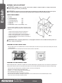
10" Table Saw
Operator’s Manual
Scie à table de 254 mm (10 po)
Manuel d’utilisation
Sierra de mesa de 10 pulg. (254 mm)
Manual del Operario
GTS10S
English
10" Table Saw, 15 AMP
Operator’s Manual
Specifications:
•
•
•
•
•
•
•
•
•
•
•
Model # GTS10S
Description: 10" Table Saw
Input: 120V ~ AC, 60Hz, 15.0 Amp
Blade Size: 10" (254 mm)
Blade Bevel: 0-45 Degrees
No-Load Blade Speed: 4,800 RPM
Arbor Size: 5/8" (16 mm)
Table Size: 26" L x 16" W
Cutting Capacity at 90 degrees: 3"
Cutting Capacity at 45 degrees: 2-1/2"
Includes: Table Saw, 60T Carbide Blade, Miter Gauge, Rip Fence, Push-Stick, Metal Stand and Wrenches.
Warning:
To reduce the risk of injury, user must read and understand this operator’s manual before operating this tool. Save this
Manual for future reference.
Toll-Free Help Line: 1-888-552-8665.
wear your
Warning:
Safety glasses
foresight is better
Than no sight
The Operation of any power tool can result in foreign objects being thrown into your eyes, which can result in severe eye
damage. Before beginning tool operation, always wear safety goggles or safety glasses with side shields and a full face shield
when needed. We recommend Wide Vision Safety Mask for use over eyeglasses or standard safety glasses with side shields.
Always wear eye protection which is marked to comply with ANSI Z87.1.
Look for this symbol to point out important safety precautions.
It means attention!!! Your safety is involved.
GENERAL SAFETY RULES
Warning:
Some dust created by power sanding, sawing, grinding, drilling, and other construction activities contains chemicals
known to cause cancer, birth defects or other reproductive harm. Some examples of these chemicals are:
•
•
•
lead from lead-based paints,
crystalline silica from bricks and cement and other masonry products, and
arsenic and chromium from chemically treated lumber.
Your risk from these exposures varies, depending on how often you do this type of work. To reduce your exposure
to these chemicals: work in a well ventilated area, and work with approved safety equipment, such as those dust
masks that are specially designed to filter out microscopic particles.
10" Table Saw
Operator’s Manual GTS10S
English
Warning: READ AND UNDERSTAND ALL WARNINGS, CAUTIONS AND OPERATING INSTRUCTIONS BEFORE USING THIS
EQUIPMENT. Failure to follow all instructions listed below may result in electric shock, fire and/or serious
personal injury.
SAVE THESE INSTRUCTIONS
WORK AREA SAFETY:
• Keep your work area clean and well lit. Cluttered benches and dark areas invite accidents.
• Do not operate power tools in explosive atmospheres, such as in the presence of flammable liquids, gases, or dust. Power tools create sparks which may ignite the dust or fumes.
• Keep bystanders, children, and visitors away while operating a power tool. Distractions can cause you to lose
control.
ELECTRICAL SAFETY
• Power tool plugs must match the outlet. Never modify the plug in any way. Do not use any adapter plugs in any earthed
(grounded) power tools. Double insulated tools are equipped with a polarized plug (one blade is wider than the other). This plug will fit in a
polarized outlet only one way. If the plug does not fit fully in the outlet, reverse the plug. If it still does not fit, contact a qualified electrician to
install a polarized outlet. Do not change the plug in any way. Double insulation eliminates the need for the three wire grounded power cord and
grounded power supply system.
• Do not expose power tools to rain or wet conditions. Water entering a power tool will increase the risk of electric shock.
• Avoid body contact with earthed or grounded surfaces such as pipes, radiators, ranges and
refrigerators. There is an increased risk of electric shock if your body is grounded.
• Do not abuse the cord. Never use the cord for carrying, pulling or unplugging the power tool. Keep cord away from heat. Oil, sharp
edges or moving parts. Damaged cords increase the risk of electric shock.
• When operating a power tools outside, use an extension cord suitable for outdoor use. These cords are
rated for outdoor use and reduce the risk of electric shock.
• Do not use AC only rated tools with a DC power supply. While the tool may appear to work. The electrical components
of the AC rated tool are likely to fail and rate a hazard to the operator.
PERSONAL SAFETY
• Stay alert, watch what you are doing and use common sense when operating a power tool. Do not use tool while tired or under the
influence of drugs, alcohol, or medication. A moment of inattention while operating power tools may result in serious personal injury
• Use safety equipment. Always wear eye protection. Safety equipment such as dust mask, non-skid safety shoes, hard hat, or hearing
protection for appropriate conditions will reduce personal injuries.
• Dress properly. Do not wear loose clothing or jewelry. Keep your hair, clothing and gloves away from moving parts. Loose clothes,
jewelry or long hair can be caught in moving parts. Air vents may cover moving parts and should be avoided.
• Avoid accidental starting. Ensure the switch is in the off position before plugging in. Carrying power tool with your finger on the
switch or plugging in power tools that have the switch on invites accidents.
• Remove any adjusting keys or wrenches before turning the power tool on. A wrench or key that is left
attached to a rotating part of the tool may result in personal injury.
• Do not overreach. Maintaining proper footing and balance at all times. Loss of balance can cause an injury in unexpected situation.
• If devices are provided for connection of dust extraction and collection facilities, ensure these are
connected and properly used. Use of these devices can reduce dust related hazards.
• Do not use a ladder or unstable support. Stable footing on a solid surface enables better control of the tool in unexpected
situations.
• Keep tool handles dry, clean and free from oil and grease. Slippery handles cannot safely control the tool.
TOOL USE AND CARE
• Secure the work piece. Use clamp or other practical way to hold the work piece to a stable platform. Holding the work piece by hand
or against your body is unstable and may lead to loss of control.
10" Table Saw
Operator’s Manual GTS10S
English
• Do not force the power tool. The tool will perform the job better and safer at the feed rate for which it is designed. Forcing the tool
could possible damage the tool and may result in personal injury.
• Use the correct power tool for the job. Don’t force the tool or attachment to do a job for which it is not designed.
• Do not use tool if switch does not turn it on or off. Any tool that cannot be controlled with the switch is dangerous and
must be repaired or replaced by an authorized service center.
• Turn power tool off, and disconnect the plug from the power source and/or battery pack from the power tool before making
any adjustments, changing the accessories, or storing the tools. Such preventive safety measure reduce the risk of an accidental start up
which may cause personal injury.
• Store idle tool out of reach of children and other inexperienced persons. It is dangerous in the hand of untrained
users.
• Maintain power tools with care. Check for proper alignment and binding of moving parts, component breaks, and any other
conditions that may affect the tool’s operation. A guard or any other part that is damaged must be properly repaired or replaced by an
authorized service center to avoid risk of personal injury.
• Use recommended accessories. Using accessories and attachments not recommended by the manufacturer or intended for
use on this type tool may cause damage to the tool or result in personal injury to the user. Consult the operator’s manual for recommended
accessories.
• Keep cutting tools sharp and clean. Properly maintained cutting tools with sharp cutting edges are less likely to bind and are
easier to control.
• Feed the work piece in the correct direction and speed. Feed the work piece into a blade, cutter, or abrasive surface
against the direction of the cutting tool’s direction of rotation only. Incorrectly feeding the work piece in the same direction may cause the work
piece to be thrown out at high speed.
• Never leave the tool running unattended, turn the power off. Do not leave the tool until it comes to a complete stop.
• Never start the power tool when any rotating component is in contact with the work piece.
Warning:
USE OF THIS TOOL CAN GENERATE AND DISBURSE DUST OR OTHER AIRBORNE PARTICLES, INCLUDING WOOD
DUST, CRYSTALLINE SILICA DUST AND ASBESTOS. Direct particles away from face and body. Always operate
tool in a well-ventilated area and provide for proper dust removal. Use dust collection system wherever possible.
Exposure to the dust may cause serious and permanent respiratory or other injury, including silicosis (a serious lung
disease), cancer, and death. Avoid breathing the dust, and avoid prolonged contact with the dust. Allowing dust to
get into your mouth or eyes, or lay on your skin may promote absorption of harmful material. Always use properly
fitting NIOSH/OSHA approved respiratory protection appropriate for dust exposure, and wash exposed areas with
soap and water.
SERVICE
• Have Your Power Tool Serviced by a qualified repair person using only identical replacement parts.
This will ensure that the safety of the power tool is maintained.
• Service Your Power Tool periodically. When cleaning a tool, be careful not to disassemble any portion of the tool since internal
wires may be misplaced or pinched or safety guard return spring may be improperly installed.
Warning: READ AND UNDERSTAND ALL WARNINGS, CAUTIONS AND OPERATING INSTRUCTIONS BEFORE USING THIS
EQUIPMENT. Failure to follow all instructions listed below may result in electric shock, fire and/or serious
personal injury.
SAVE THESE INSTRUCTIONS
10" Table Saw
Operator’s Manual GTS10S
English
EXTENSION CORDS
Grounded tools require a three wire extension cord. Double insulated tools can use either a two or three wire extension cord. As the distance from the power supply outlet increases, you must use a heavier gauge extension cord. Using extension cords with inadequately sized
wire causes a serious drop in voltage, resulting in loss of power and possible tool damage. Refer to the table shown below to determine the required
minimum wire size.
The smaller the gauge number of the wire, the greater the capacity of the cord. For example: a 14-gauge cord can carry a higher current than a 16gauge cord. When using more than one extension cord to make up the total length, be sure each cord contains at least the minimum wire size required. If you are using one extension cord for more than one tool, add the nameplate amperes and use the sum to determine the required minimum wire size.
Guidelines for Using Extension Cords
• If you are using an extension cord outdoors, be sure it is marked with the suffix “W-A” (“W” in Canada) to indicate that it is acceptable for outdoor use.
• Be sure your extension cord is properly wired and in good electrical condition. Always replace a damaged extension cord or have it repaired by a
qualified person before using it.
• Protect your extension cords from sharp objects, excessive heat, and damp or wet areas.
Recommended Minimum Wire Gauge for Extension Cords (120 Volt)
Nameplate
Amperes
(At Full Load)
Extension Cord Length
0–2.0
25 Feet
50 Feet
75 Feet
100 Feet
150 Feet
200 Feet
18
18
18
18
16
16
2.1–3.4
18
18
18
16
14
14
3.5–5.0
18
18
16
14
12
12
5.1–7.0
18
16
14
12
12
10
7.1–12.0
18
14
12
10
8
8
12.1–16.0
14
12
10
10
8
6
16.1–20.0
12
10
8
8
6
6
SPECIFIC SAFETY RULES FOR TABLE SAW
Warning:
DO NOT LET COMFORT OR FAMILIARITY WITH PRODUCT (GAINED FROM REPEATED USE) REPLACE STRICT
ADHERENCE TO PRODUCT SAFETY RULES. If you use this tool unsafely or incorrectly, you can suffer serious
personal injury!
• Do not cut metals with the table saw. Table saws are designed to cut wood-like or plastic materials. However, some wood and
plastic materials are quite hard and slippery. The anti-kickback pawls may not stop kick back. Do not stand, or let anyone stand in line with
potential kickback.
• To avoid tipping your table saw in operation, firmly BOLT it to a work stand or bench. Long work pieces
need extra support on the out-feed side.
• Unplug saw from power source before making adjustments, repairs, maintenance or storing.
Accidental start up can cause serious personal injury.
• Do not turn on the table saw before clearing the table of all tools, wood scraps, etc, except the work piece
and related feed or supporting devices
• Wear eye and hearing protection. Always use safety glasses with side shields, unless otherwise specified, everyday glasses
provide only limited impact resistance, they are not safety glasses, use only approved certified safety equipment; eye protection should comply
with ANSI z87.1 standards, protective hearing equipment should comply with ANSI s3.19 standards.
• Protect your lungs. Wear face or dust mask. Following this rule will reduce the risk of personal injury.
• Tie back long hair and roll long sleeves above the elbow. Do NOT wear loose fitting gloves, loose clothing, jewelry and
other items which can be caught in rotating parts and cause serious personal injury.
10" Table Saw
Operator’s Manual GTS10S
English
• Always use blade guard, splitter and anti-kickback pawls on all through cutting operations. The guard
system is designed to reduce the intensity of kickback and keep your hands away from the spinning blade.
• Always secure the work piece against rip fence or miter gauge.
• Always use push stick for ripping narrow stock so your hand does not come close to the saw blade. Use a push block or
feather board for non-through cuts
• Never cut freehand, which means using only your hands to support or guide the work piece. Always use rip fence or miter gauge to
position and guide the work
• Stand to the side of the blade and work piece. NEVER stand or hand any part of your body in line with the path of the saw
blade.
• Never reach behind blade when the saw blade is rotating. • Move rip fence out of the way when cross cutting. NEVER use rip fence as a cut off gauge when cross cutting
• Keep saw blade clean and sharp. A Dull and sticky blade will increase the risk of binding in the work piece.
• Feed the work piece through AGAINST the rotation of the blade. Feeding material from the back of the saw invites
an accident and can cause serious injury.
• Use support for the sides and back of the saw table when cutting wide or long work piece.
• Never cut one than one work piece at a time. Stacked work pieces can shift or bind and lead to unexpected contact with
blade.
• Keeping rip fence parallel to the saw blade to avoid binding or kickbacks
• Never pull the work through the spinning blade. It may cause kickback and cause serious personal injury. You can be
dragged into the blades during a kickback
• Do not rip a work piece that is twisted or warped or does not have a straight edge to guide along
the fence.
• Never make through cuts narrower than ½”. The blade guard system is not effective for narrow rip cuts and will not prevent
kickback.
• Never attempt to free a stalled saw blade without turning off the saw and unplugging the saw from
the power source.
• Avoid cutting nails or other metal pieces. Inspect for and remove all nails from the work piece.
• Always turn the saw off before unplugging the saw from power source to avoid accidental starting when replugging into to power source. Never leave table saw unattended while connected to a power source.
• Use only accessories rated for the speed recommended on the tool warning label or higher. The blade
for this table saw must be 10” (254mm) in diameter, rated at least 4,800 rpm or higher with 5/8” arbor. Accessories running at speeds greater
than rated can fly apart and cause personal injury.
• Save these instructions. Refer to them frequently and use to instruct other users
Warning: USE OF THIS TOOL CAN GENERATE AND DISBURSE DUST OR OTHER AIRBORNE PARTICLES, INCLUDING WOOD
DUST, CRYSTALLINE SILICA DUST AND ASBESTOS. Direct particles away from face and body. Always operate
tool in a well-ventilated area and provide for proper dust removal. Use dust collection system wherever possible.
Exposure to the dust may cause serious and permanent respiratory or other injury, including silicosis (a serious lung
disease), cancer, and death. Avoid breathing the dust, and avoid prolonged contact with the dust. Allowing dust to
get into your mouth or eyes, or lay on your skin may promote absorption of harmful material. Always use properly
fitting NIOSH/OSHA approved respiratory protection appropriate for dust exposure, and wash exposed areas with
soap and water.
SAVE THESE INSTRUCTIONS
10" Table Saw
Operator’s Manual GTS10S
English
GLOSSARY OF WOOD-WOKING TERMS:
Work Piece-- A piece of wood on which the cutting operation is being performed.
Anti-Kickback Pawls-- Device which, when properly installed and maintained, is designed to stop the work piece from being
kicked back toward the operator during the operation.
Arbor-- The shaft on which a cutting tool is mounted.
Bevel Cut-- A cutting operation made with an angled blade.
Compound Miter Cut -- A single cut made with both a miter angle and a bevel angle.
Cross Cut -- A cut or shaping operation made across the work piece.
Dado -- A non-through cut which produces a square sided notch or trough in the work piece.
Feather board -- A device used to help control the work piece by guiding it securely against the table or fence during any rip
cut operation.
Freehand -- Performing a cut without using a fence, miter gauge, fixture, hold down clamp, or other proper device to keep the
work piece from twisting during the cut – not recommended.
Gum -- A sticky, sap-based residue from wood products.
Heel -- Misalignment of the blade. Heel can cause binding, kickback, excessive force burning the work piece or splintering
Kerf -- The amount of material removed by the blade in a through cut, or the slot produced by the blade in non-through or partial
cut.
Kickback -- An uncontrolled grabbing or throwing of the work piece back toward the front of the saw, associated with the work
piece closing the kerf and pinching the blade or otherwise placing tension on the blade.
Leading End -- The end of the work piece, which during a rip type operation is pushed into the cutting tool first.
Miter Cut -- A cutting operation made with the wood at any angle other than 90 degree to the blade.
Molding -- A cut which produces a special shape in the work piece, used for joining or decoration.
Non-Through Cut -- Any cutting operation where the blade does not extend completely through the thickness of the work
piece
Push Block -- A device used to feed the work piece through the saw during narrow rip type operations where a push stick can
not be used. It also helps keep the operator's hands well away from the blade.
Push Stick -- A device used to feed the work piece through the saw to help keep the operator's hands well away from the
blade.
Rabbet -- A notch in the edge of the work piece.
Resin -- A sticky, sap-based substance that has hardened.
Rip Cut -- A cutting or shaping operation made along the length of the work piece.
Rip Fence -- Adjustable guide used in ripping cuts to keep the work piece parallel to the saw blade.
RPM -- Revolutions per Minute. The number of turns completed by a spinning object in one minute
Saw Blade Path -- The area over, under, behind, or in front of the blade. As it applies to the work piece, that area which will
be, or has been, cut by the blade.
10" Table Saw
Operator’s Manual GTS10S
English
1
YOUR 10" TABLE SAW
4
3
2
5
6
7
1. Die-Cast Aluminum Table
2. Saw Blade
3. Saw Blade Guard
4. Splitter
5. Anti-Kickback Pawls
6. Rip Fence
7. Miter Gauge
8. Push Stick
9. Blade Control Wheel
10. ON/OFF Switch with Safety Key
11. Reset Button
12. Blade Angle Lock
13. Base
14. Steel Work Stand
15. Miter Gauge Storage
16. Rip Fence Storage
17. Sawdust Port
17
9
12
16
10
13
11
14
15
8
UNPACKING AND CONTENTS
ITEM DESCRIPTION
1. Table Saw Assembly 2. Miter Gauge 3. Rip Fence
4. Blade Control Wheel Handle
5. Blade Guard Assembly 6. Push Stick 7. Allen Wrench 8. Blade Change Wrench 9. Long Top Brackets (A) 10. Short Top Brackets (B) 11. Long Support Bracket (C)
12. Short Support Bracket (D)
13. Stand Legs 14. Rubber Feet 15. Screws, Washers & Nuts for Stand Assembly
16. Bolts, Washers & Nuts for Securing Saw on Stand
17. Operator’s Manual and other instructions QTY
1
1
1
1
1
1
2
2
2
2
2
2
4
4
24 Sets
4 Sets
(not shown)
10" Table Saw
Operator’s Manual 3
1
2
5
7
8
16
15
9
4
10
6
11
12
14
13
GTS10S
English
ASSEMBLY AND ADJUSTMENT
Warning: DO NOT connect to power source until assembly is complete. Failure to comply could result in
accidental starting and serious personal injury
Warning: If any part is missing or damaged, do not attempt to assembly the table saw, plug in the power
source, or turn the switch on until the missing or damaged part is obtained and it installed properly.
WORK STAND ASSEMBLY
Part Needed
9. Long Top Brackets (A) 2 pcs
10. Short Top Brackets (B) 2 pcs
11. Long Support Bracket (C)
2 pcs
12. Short Support Bracket (D)
2 pcs
13. Stand Legs 4 pcs
14. Rubber Feet 4 pcs
15. Screws, Washers & Nuts for Stand Assembly 24 Sets
10
9
15
Use Screws, Washers and Nuts 15 to attach the stand pieces. Do not
tighten the screws completely until leg stand is completely assembly.
(See FIG. 1)
12
1. Attach the short top brackets 10 (B) to the stand legs 13.
2. Attach the long top brackets 9 (A) to the stand legs 13
3. Attach the short support brackets 12 (D) to the stand legs 13
4. Attach the long support brackets 11 (C) to the stand leg 13
5. Tap the four rubber feet 14 onto the bottom of the stand legs 13
6. Tighten all Fasteners.
11
13
14
FIG. 1
Warning: After completing adjustments, securely tighten all fasteners. An unstable stand may shift in use
and cause serious personal injury.
MOUNTING THE TABLE SAW ON STAND
1.Place the table saw on to the assembled stand so that the four mounting holes in the base of the saw are over the four mounting slots in the two
long top brackets 9
2.Secure the table saw to the stand by using the four bolts, washers and nuts 16 (See FIG.2)
16
9
FIG. 3
FIG. 2
MOUNTING THE TABLE WITHOUT STAND
When mounting table saw to a work bench or plywood, holes should be drilled through the supporting surface to the work bench or plywood and an
opening must be made the same size as the opening in the bottom of the saw using the dimensions illustrated so the saw dust can drop through.
1.Place the saw on the mounting surface, and mark the location of the four 3/8” mounting holes.
2.Remove the saw. Drill 3/8” holes in the mounting surface
3.Mark an 11” x11” square centered between four mounting holes.
4.Cut out and remove the square. (See FIG.3 )
5.This opening will allow sawdust to fall through the saw base
6.Place the saw on the work bench, and align the mounting holes of the saw with holes that have been drilled through the surface.
7.Secure the saw to the work bench using bolts and nuts.
10" Table Saw
Operator’s Manual GTS10S
English
ASSEMBLING THE BLADE CONTROL WHEEL HANDLE
Tighten the screw through the wheel handle 4 onto the blade control wheel.
Warning: To prevent personal Injury, always unplug the saw from
power source before make any adjustments.
FIG. 4
BLADE GUARD ASSEMBLY INSTALLATION
The saw blade guard is supplied already assembled from the factory. (See FIG. 4)
It must be installed on the guide stick (1) on the table saw (See FIG 5)
1
Remove the stop bolt (3) from guide stick; push the bracket (2) for the saw guard over the guide
stick. Tighten the four screws (4). Secure the stop by using the stop bolt, washer (3) as shown.
(FIG 6)
2
BLADE GUARD ADJUSTMENT
3
The saw blade guard is also used as a splitter (5). It must be precisely In LINE with the saw blade
Loosen four screws (4 ) and the bolt (3 ) using hex wrench provided, Adjust the splitter(5) to make
sure it is precisely in LINE with the saw blade. Once aligned, tighten all screws and bolt.
4
Height of splitter can be adjusted FIG. 5
FIG. 6
5
1.Loosen two bolts (6)
2.Raise the saw blade to its highest position at 90 degree angle.
3.Adjust the splitter (5 ) to about at least 1/8” (3 mm) above from the blade tips.
4.Tighten the two bolts (6) to secure the splitter position. Again make sure the splitter is still in LINE with saw blade. (See FIG 7)
6
FIG. 7
MITER GAUGE INSTALLATION
The miter gauge is pre-assembled at the factory. To install it, simply slide miter gauge guide into the
miter gauge groove (7) on the saw table as shown in FIG. 8
FIG. 8
NOTE: There are two miter gauge grooves, one on either side of the blade. When making 90°
Cross cut, you may use either of the grooves. When bevel cutting, use the groove on the right side so
that the blade is tilted away from the miter gauge and your hand.
MITER GAUGE ADJUSTMENT
To adjust the miter gauge angle, loosen miter gauge lock knob (1) and rotate the miter
gauge body so that the indicator (3) points to desired position. Then tighten the lock knob. (See FIG
9)
To adjust the Miter Gauge Fence, loosen two lock knobs (4) and slide the fence to the
desired position. Then tighten the lock knobs. (See FIG 9)
7
FIG. 9
6
To verify Miter Gauge Accuracy:
1.Set the miter gauge body to 0° position. This is the set up for 90° Cutting
2.Cross cut a piece of scrap wood. Check it with a square to see if the piece of wood was cut at
90°. If it was not 90°, adjust the Miter Gauge body and make additional cuts until you have made
90° cut.
3.Loosen indicator adjustment screw (2) so that indicator (3) points to the 0° mark on the scale and
then tighten screw (2)
5
4
3
1
2
2
FIG. 10
RIP FENCE INSTALLATION
The rip fence is pre-assembled at the factory. To install the Rip Fence, place the end furthest (2) from
the lock handle (1) so that flange is over the rear edge of the table, then lower the end closest to the
handle over the front rail. When Lock down handle (1) is in the UP position, the flanges are relaxed,
allow you to re-position the Rip Fence. When Lock down handle is in DOWN position, the flanges are
locked with rails in place. (See FIG 10)
10" Table Saw
Operator’s Manual GTS10S
UP
DOWN
1
English
Warning: The Rip Fence must be parallel with the Saw Blade in order
to prevent Kickback when rip cutting.
4
RIP FENCE ADJUSTMENT
Warning: To prevent personal Injury, always unplug the saw from
power source before make any adjustments.
To adjust the Rip Fence, lift the lock handle (1) to UP position. Use indicator (3) on the fence to slide
the Rip Fence to desired position. Make sure the front bar on the Rip Fence is flush against front rail. Then
lock DOWN the lock handle.
FIG. 11
1
2
5
To adjust the tension on the Rip Fence, you may turn the tension adjustment knob (4)
clockwise to increase the tension or turn counterclockwise to decrease the tension.
FIG. 12
To align rip fence, please follow the steps below:
1.Lift the lock handle (1) to UP position.
2.Slide the Rip Fence by handle until it is alongside the saw blade. The fence should touch the “SET”
teeth at the front and rear of the blade. If not, continue the following the steps
3.Loosen the two hex screws (5) on the top front section of the fence
4.Move fence until it touches the teeth and is parallel to the blade
5.Hold fence in place and lower the lock handle, then tighten hex screws
6
3
7
The distance of rip fence body from the blade when rip cutting on the right side of the blade is determined
by lining the Distance Indicator (3) with the desired dimension on the scale( 6). To adjust Rip Fence
Distance Indicator, loosen the adjustment screw (7), adjust the indicator (4) and then tighten screw.
4
BLADE HEIGHT ADJUSTMENT
FIG. 13
1.Unplug the saw from the power supply.
2.Turn the blade control wheel (1). Turning it clockwise lowers the blade. Turning it counterclockwise
elevates it. (See FIG 13)
3.For through cuts, place the work piece to be cut flush against blade, set the blade so that tips on the
top of blade are about an 1/8” (3 mm) higher than the work piece and valley between the teeth is lower
than the work piece
4.For non-through cuts, use a ruler to measure from the table surface to the tip of the uppermost tooth
on the blade.
2
1
3
90° AND 45° POSITIVE STOPS ADJUSTMENT
The saw has positive stops that will quickly position the saw blade at 90° or 45° to the table. Make the
following adjustments only when it is needed.
Adjust 90° Positive Stop
1.Raise the blade to highest possible position by turning blade control wheel(1) counterclockwise
2.Loosen the bevel adjustment knob (2). Push the blade control wheel (1) and turn clockwise as far as
possible (See FIG 13)
3.Place a combination square flush on the table and flush against the blade to determine if the blade is at
a 90° angle to the table
4.If the blade is not at a 90° angle to the table. Loosen the jam nut (underneath table) and turn the 90°
adjusting socket head screw (5) left to reduce the angle or right to increase the angle (FIG 14)
FIG. 14
Adjust 45° Positive Stop
1.Raise the blade to highest possible position by turning blade control wheel (1) counterclockwise
2.Loose the bevel adjustment knob (2). Push blade control wheel (1) and turn left as far as possible
3.Place a combination square on the table and flush against the blade to determine if the blade is at a
45° angle to the table
4.If blade is not at a 45° angle to the table, loosen the jam nut (underneath table) turn the 45° adjustment
socket head screw (6 ) left to reduce the angle or right to increase the angle. (FIG 14)
10" Table Saw
Operator’s Manual GTS10S
6
5
English
Warning: To prevent personal Injury, always unplug the saw from power source before make any
adjustments.
BLADE BEVEL INDICATOR ADJUSTMENTS
1.Loosen bevel adjustment knob (2 ), push blade control wheel (1) and turn clockwise to position the blade at 90° measured by using combination
square. (FIG. 13)
2.Loosen the holding screw (4), position the pointer over 0° and tighten the screw. (FIG 13)
NOTE: Always make a trial cut on a piece of wood when make critical cuts. Measure the cut accuracy.
BLADE BEVEL ADJUSTMENT
1.Loosen bevel adjustment knob (2) (FIG 13)
2.Push blade control wheel (1) and turn the blade control wheel to desired blade angle. 0° on bevel scale for 90° cutting. (FIG 13)
3.Tighten the bevel adjustment knob (2). (FIG 13)
Warning: Make sure bevel adjustment knob is tightened before each use to avoid risk of personal injury.
OPERATION:
Warning: DO NOT turn on the table saw before clearing the table of all tools, wood scraps, etc, except
the work piece and related feed or supporting devices.
3
ON/OFF SWITCH WITH SAFETY KEY
FIG. 15
The saw is equipped with a removable ON/OFF switch safety key (2) (yellow part on
switch) to protect against unauthorized use. If key is removed, the saw can not be turned
on. (FIG 15)
1.To turn the saw ON, insert the safety key into the switch (1), Pull the bottom end of switch
upward to the ON position.
2.To turn the saw OFF, push the switch downward to the OFF position.
3.To lock the switch in the OFF position, remove the safety key.
1
2
NOTE: If safety key is removed during the operation, the saw may be turned off, but can not be re-turned on
without inserting the safety key.
OVERLOAD RESET SWITCH
Warning: To prevent accidental startup if overload reset switch is pushed, the ON/OFF switch must be
in the OFF position and plug should be removed from the power source while cooling down. Overheating may be
caused by dull blade or misaligned parts. Inspect your saw for proper setup before using it again.
Your saw is equipped with an overload rest switch (3-FIG 15) that will allow the motor to be restarted after it shuts off due to overloading or low
voltage. If motor stops during the operation, do the following steps:
1.Turn the ON/OFF switch to the OFF position
2.Wait about five minuets for the motor to cool down
3.Push in the reset button (3-FIG 15)
4.Turn the ON/OFF switch to the ON position
SAWDUST PORT
The sawdust port is located at the back side of the saw base. A dust collection system can be attached to this port to help remove sawdust from the
work area.
PUSH STICK AND PUSH BLOCK
A plastic push stick is supplied for rip cutting widths of 2” to 6”
Use auxiliary fence and push block for rip cutting widths narrower than 2”. When ripping, apply the feed force to the section of the work piece
between the saw blade and the rip fence.
10" Table Saw
Operator’s Manual GTS10S
English
APPLICATIONS
Cutting Tips:
1. Make sure the kerf is made on the scrap side of the measuring line.
2. Cut the wood with the finish side up
3. Always have a proper support for the wood as it comes out of the blade.
4. Make a test cut for important cuts
5. Always use the correct blade depth setting. The Top of the blade teeth should clear the work piece by 1/8” (3mm) to ¼” (6 mm)
6. Inspect the work piece for knots or nails before beginning a cut. Remove any loose knots or nails with a hammer
7. Always use clean, sharp, properly-set blades, Never make a cut with dull blade
8. When making a cut, use steady, Even pressure, Never force a cut
9. Do NOT cut wet or warped lumber
10.Always hold your work piece firmly with both hands or use push stick or push block.
Cross Cutting:
Warning: Make sure the blade guard assembly is properly installed to avoid serious personal injury
1.
2.
3.
4.
5.
Remove the rip fence from the table surface
Position Miter Gauge to 0°
Make sure all loose pieces have been removed from the table surface and work piece is not in contact with blade
Turn ON/OFF switch to the ON position
Position the work piece flat on the table with edge flush against miter gauge fence. Wait until blade reaches full speed before feeding the work
piece into the blade
6. Use two hands to slowly feed the work piece and miter gauge toward the blade. Use the hand furthest from the blade to keep the work piece flush
against miter gauge fence and use your other hand to push the miter gauge and work piece toward the blade. Stand slightly to the side of the
blade to reduce the risk of injury should kickback occur.
7. Continue feeding the work piece into the blade until the cut has been completed.
8. Once the cut has been completed, pull the work piece back toward you
9. Turn the switch off
10.After blade has stopped completely, remove the cut off piece.
Rip Cutting:
Warning: Make sure the blade guard assembly is properly installed to avoid serious personal injury.
1.
2.
3.
4.
5.
6.
Remove the Miter Gauge from the table
Place the rip fence on the desired distance from the blade. Remember to allow for the kerf.
Make sure all loose items have been removed from the table and that work piece is not contact with the blade
If work piece is larger than 36” long, place a support with the same height as table behind the saw for the cut work
Turn ON/OFF switch to ON position
Position the work piece flat on the table with edge flush against rip fence. Wait until blade reaches full speed before feeding the work piece into the
blade
7. Stand slightly to the side of blade to reduce the risk of injury caused should kickback occur.. Using a push stick or push block, slowly feed the work
piece toward the blade.
8. Once the work piece has made contact with the blade, use hand closest to the rip fence to guide it. Make sure the edge of the work piece keeps in
solid contact with the rip fence and table surface. If ripping a piece narrower than 4”, use a push stick to move the piece through the cut.
9. Continue feeding the work piece into the blade until the cut has been completed.
10.Once the cut has been completed, grasp the work piece from the lead end and pull it off the table surface.
11.Turn the switch off
12.After blade has stopped completely, remove the cut off piece
Warning:To avoid serious personal injury, never push a small piece of wood into the blade with your hand.
Always use a push stick or push block.
10" Table Saw
Operator’s Manual GTS10S
English
Miter Cross Cutting:
Warning: Make sure the blade guard assembly is properly installed to avoid serious personal injury
1.
2.
3.
4.
5.
Remove the rip fence from the table surface
Position Miter Gauge to the desired degree. (0°-60°). (Refer to Miter Gauge Adjustment).
Make sure all loose pieces have been removed from the table surface and work piece is not in contact with blade
Turn ON/OFF switch to the ON position
Position the work piece flat on the table with edge flush against miter gauge fence. Wait until blade reaches full speed before feeding the work
piece into the blade
6. Use two hands to slowly feed the work piece and miter gauge toward the blade. Use the hand furthest from the blade to keep the work piece flush
against miter gauge fence and use your other hand to push the miter gauge and work piece toward the blade. Stand slightly to the side of the blade
to reduce the risk of injury should kickback occur.
FIG. 16
7. Continue feeding the work piece into the blade until the cut has been completed.
8. Once the cut has been completed, pull the work piece back toward you
9. Turn the switch off
10.After blade has stopped completely, remove the cut off piece.
Bevel Cross Cutting:
Warning: Make sure the blade guard assembly is properly installed to avoid serious personal injury
1.
2.
3.
4.
Remove the rip fence from the table surface
Adjust bevel angle to the desired degree. (0°-45°)
Set the blade to the correct depth. Refer to Blade Height Adjustment
Position Miter Gauge to 0°. (Refer to Miter Gauge Adjustment). Use the miter gauge in the groove to the RIGHT of the blade. It can not be used in the
groove to the LEFT because the blade guard will interfere with the cut .
5. Make sure all loose pieces have been removed from the table surface and work piece is not in contact with blade
6. Turn ON/OFF switch to the ON position
7. Position the work piece flat on the table with edge flush against miter gauge fence. Wait until blade reaches full speed before feeding the work
piece into the blade
8. Use two hands to slowly feed the work piece and miter gauge toward the blade. Use the hand furthest from the blade to keep the work piece flush
against miter gauge fence and use your other hand to push the miter gauge and work piece toward the blade. Stand slightly to the side of blade to
reduce the risk of injury should kickback occur.
FIG. 17
9. Continue feeding the work piece into the blade until the cut has been completed.
10.Once the cut has been completed, pull the work piece back toward you
11.Turn the switch off
12.After blade has stopped completely, remove the cut off piece
Compound Miter Cross Cutting
Warning: Make sure the blade guard assembly is properly installed to avoid serious personal injury
1.
2.
3.
4.
Remove the rip fence from the table surface
Adjust bevel angle to the desired degree. (0°-45°) (refer to Bevel Adjustment)
Set the blade to the correct depth
Position the Miter Gauge to the desired degree. (0°-60°) (Refer to Miter Gauge Adjustment). Use the miter gauge in the groove to the RIGHT of the
blade. It can not be used in the groove to the LEFT because the blade guard will interfere
5. Make sure all loose pieces have been removed from the table surface and work piece is not in contact with blade
6. Turn ON/OFF switch to the ON position
7. Position the work piece flat on the table with edge flush against miter gauge fence. Wait until blade reaches full speed before feeding the work
piece into the blade
8. Use two hands to slowly feed the work piece and miter gauge toward the blade. Use the hand furthest from the blade to keep the work piece flush
against miter gauge fence and use your other hand to push the miter gauge and work piece toward the blade. Stand slightly to the side of blade to
reduce the risk of injury should kickback occur.
9. Continue feeding the work piece into the blade until the cut has been completed.
10.Once cut has been completed, pull the work piece back toward you
11.Turn the switch off
12.After blade has stopped completely, remove the cut off piece
10" Table Saw
Operator’s Manual GTS10S
English
Non-Through Cutting
Non-through cutting are in cutting grooves, rabbets and dados. This is the only type of cut made with the blade guard assembly removed. You must
make sure the entire blade guard assembly is reinstalled properly after completion of this type of cut.
Warning: Never feed work piece through with your hands when making non-through cut, such as rabbets
or dados. Always use push stick and push block. Failure to do so can result in serious personal injury
Important: The table saw is a highly versatile tool, capable of a wide range of applications which cannot be
covered in this manual. Do Not attempt to perform cuts not covered in this manual unless you are thoroughly
familiar with procedures and featuring. Visit your local library for books on woodworking techniques.
MAINTENANCE
To Remove or Change the Blade
Warning:Always unplug the saw from power source before maintenance to avoid risk of serious personal
injury.
To remove the blade:
1.Remove the two screws (1) holding the metal plate (2) in place, and remove the metal plate (FIG. 18)
2.Raise the blade to the highest possible position
3.To keep the arbor from rotating, place one of the open ended wrenches (4) on the flange flats (See FIG.19)
4.Place the second open ended wrench (3) on the arbor nut (See FIG 19)
5.Turn the second wrench (3) clockwise to tighten, counterclockwise to loosen. Loosen and remove the arbor nut (FIG. 19)
6.Remove the flange and pull of the blade off the motor shaft.
FIG. 19
FIG. 18
2
1
4
3
To install the blade, reverse the procedure.
Important: Blade rotation is counter-clockwise when seeing from the right side of the saw. Make sure the
rotation direction mark on the blade matches with that.
Lubrication
This table saw are permanently lubricated at the factory and requires no additional lubrication.
10" Table Saw
Operator’s Manual GTS10S
English
TROUBLE SHOOTING
Problem
Possible Cause
Solution
Saw will not start
1.
2.
3.
4.
Saw is not plugged in
Fuse blown or circuit breaker
cord is damaged
Debris in ON/OFF switch
1. Plug to power source
2. Replace fuse or reset circuit break.
3. Have power cord replaced by Authorized
4. Clean any debris accumulated
Does not make accurate 45°
1. Positive stop not adjusted
2. Blade angle pointer not set
accurately
Material Pinched Blade when
1. Rip fence not aligned with blade 1. Check and adjust the rip fence
2. Warped wood, edge against
2. Select another piece of wood
fence is not straight
Material Binds on Splitter
1. Splitter not in line correctly with
blade
1. Check and align the splitter with blade
Saw makes unsatisfactory
1. Dull Blade
2. Blade mounted backward
3. Gum or resin on blade
4. Incorrect blade for work
1.
2.
3.
4.
Replace blade
Turn blade around
Remove blade and clean
Change to correct blade
Material Kicked Back from the 1. Rip fence out of adjustment
2. Splitter not in line with blade
3. Feeding stock without rip fence
4. Dull blade
5. Bevel Knob is not tight
1.
2.
3.
4.
5.
Align rip fence with miter gauge groove.
Align splitter with blade
Install and use rip fence
Replace blade
Tighten the knob
Blade does not raise or tilt
freely
1 Sawdust and dirt in
elevation/tilting mechanisms
1. Brush or blow out loose dust and dirt
Blade does not come up to
1. Extension cord is too light or too 1. Replace extension cord to adequate size
2. Low house voltage
2. Contact electrician
Saw vibrates excessively
1. Saw not mounted securely to
1. Tighten all mounting hardware
2. Bench or stand on uneven floor 2. Re-position on flat level floor
3. Damaged saw blade
3. Replace blade
1. Check the blade with square and adjust
2. Check blade with square and adjust the
Blade angle pointer
TWO-YEAR WARRANTY:
This product is warranted free from defects in material and workmanship for 2 years after date of purchase. This limited warranty does not cover
normal wear and tear or damage from neglect or accident. The original purchaser is covered by this warranty and it is not transferable. Please return
the tool to store location of purchase along with your receipt, and you will receive a new drill or a refund. THIS PRODUCT IS NOT WARRANTED IF
USED FOR INDUSTRIAL OR COMMERCIAL PURPOSES.
TOLL-FREE HELP LINE:
For questions about this or any other GENESIS Product, please call Toll-Free: 888-552-8665.
Or visit our website: www.richpowerinc.com
10" Table Saw
Operator’s Manual GTS10S
Richpower Industries, Inc.
736 Hampton Road
Williamston, SC USA
www.richpowerinc.com