1
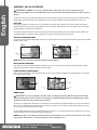
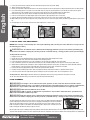
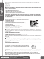
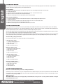
10" Slide Compound Laser Miter Saw
Operator’s Manual
Scie à onglets composés coulissante de
254 mm (10 po.), Avec guidage laser
Manuel d’utilisation
Sierra ingleteadora compuesta deslizante de
254 mm (10 pulg.), Guiada con láser
Manual del Operario
GMSUDR15L
English
10" Slide Compound Laser Miter Saw, 15 AMP
Operator’s Manual
Specifications:
• Model: GMSUDR15L
• Rated Input: 120V~AC, 60HZ, 15A
• No Load Speed: 5,000 rpm
• Blade Size:
10” (254mm)
• Arbor Size: 5/8” (16mm)
• Blade Bevel: 0-45°
• Blade Miter: 0-45° Left, 0-45° Right
• Cutting Capacity @ 90° 3” H x 12-1/5” W
• Cutting Capacity @ 45° 3” H x 8-1/4” W
• Cutting Capacity @ 0° Miter & 45° Bevel: 1-5/8” H x 12-1/5” W
• Cutting Capacity @ 45° Miter & 45° Bevel: 1-5/8” H x 8-1/4” W
Laser: - Class II Laser
- Wave Length: 650 nm
- Max Output <1.0 mw
- Runs on two AAA batteries (included)
Includes Miter Saw, 60T Carbide Tipped Blade, Hold Down Clamp, Dust Bag, Extension Wings, Rear Support Foot Bar,2-AAA Batteries for Laser and
Wrenches
Warning:
To reduce the risk of injury, user must read and understand this operator’s manual before operating this tool. Save this
Manual for future reference.
Toll-Free Help Line: 1-888-552-8665.
wear your
Warning:
Safety glasses
foresight is better
Than no sight
The Operation of any power tool can result in foreign objects being thrown into your eyes, which can result in severe eye
damage. Before beginning tool operation, always wear safety goggles or safety glasses with side shields and a full face shield
when needed. We recommend Wide Vision Safety Mask for use over eyeglasses or standard safety glasses with side shields.
Always wear eye protection which is marked to comply with ANSI Z87.1.
Look for this symbol to point out important safety precautions.
It means attention!!! Your safety is involved.
GENERAL SAFETY RULES
Warning:
Some dust created by power sanding, sawing, grinding, drilling, and other construction activities contains chemicals
known to cause cancer, birth defects or other reproductive harm. Some examples of these chemicals are:
•
•
•
lead from lead-based paints,
crystalline silica from bricks and cement and other masonry products, and
arsenic and chromium from chemically treated lumber.
Your risk from these exposures varies, depending on how often you do this type of work. To reduce your exposure
to these chemicals: work in a well ventilated area, and work with approved safety equipment, such as those dust
masks that are specially designed to filter out microscopic particles.
10" Slide Compound Laser Miter Saw
Operator’s Manual GMSUDR15L
English
Warning: READ AND UNDERSTAND ALL WARNINGS, CAUTIONS AND OPERATING INSTRUCTIONS BEFORE USING THIS
EQUIPMENT. Failure to follow all instructions listed below may result in electric shock, fire and/or serious
personal injury.
SAVE THESE INSTRUCTIONS
WORK AREA SAFETY:
• Keep your work area clean and well lit. Cluttered benches and dark areas invite accidents.
• Do not operate power tools in explosive atmospheres, such as in the presence of flammable liquids, gases, or dust. Power tools create sparks which may ignite the dust or fumes.
• Keep bystanders, children, and visitors away while operating a power tool. Distractions can cause you to lose
control.
ELECTRICAL SAFETY
• Power tool plugs must match the outlet. Never modify the plug in any way. Do not use any adapter plugs in any earthed
(grounded) power tools. Double insulated tools are equipped with a polarized plug (one blade is wider than the other). This plug will fit in a
polarized outlet only one way. If the plug does not fit fully in the outlet, reverse the plug. If it still does not fit, contact a qualified electrician to
install a polarized outlet. Do not change the plug in any way. Double insulation eliminates the need for the three wire grounded power cord and
grounded power supply system.
• Do not expose power tools to rain or wet conditions. Water entering a power tool will increase the risk of electric
shock.
• Avoid body contact with earthed or grounded surfaces such as pipes, radiators, ranges and
refrigerators. There is an increased risk of electric shock if your body is grounded.
• Do not abuse the cord. Never use the cord for carrying, pulling or unplugging the power tool. Keep cord away from heat. Oil, sharp
edges or moving parts. Damaged cords increase the risk of electric shock.
• When operating a power tools outside, use an extension cord suitable for outdoor use. These cords are
rated for outdoor use and reduce the risk of electric shock.
• Do not use AC only rated tools with a DC power supply. While the tool may appear to work. The electrical components
of the AC rated tool are likely to fail and rate a hazard to the operator.
PERSONAL SAFETY
• Stay alert, watch what you are doing and use common sense when operating a power tool. Do not use tool while tired or under the
influence of drugs, alcohol, or medication. A moment of inattention while operating power tools may result in serious personal injury
• Use safety equipment. Always wear eye protection. Safety equipment such as dust mask, non-skid safety shoes, hard hat, or hearing
protection for appropriate conditions will reduce personal injuries.
• Dress properly. Do not wear loose clothing or jewelry. Keep your hair, clothing and gloves away from moving parts. Loose clothes,
jewelry or long hair can be caught in moving parts. Air vents may cover moving parts and should be avoided.
• Avoid accidental starting. Ensure the switch is in the off position before plugging in. Carrying power tool with your finger on the
switch or plugging in power tools that have the switch on invites accidents.
• Remove any adjusting keys or wrenches before turning the power tool on. A wrench or key that is left
attached to a rotating part of the tool may result in personal injury.
• Do not overreach. Maintaining proper footing and balance at all times. Loss of balance can cause an injury in unexpected situation.
• If devices are provided for connection of dust extraction and collection facilities, ensure these are
connected and properly used. Use of these devices can reduce dust related hazards.
• Do not use a ladder or unstable support. Stable footing on a solid surface enables better control of the tool in unexpected
situations.
• Keep tool handles dry, clean and free from oil and grease. Slippery handles cannot safely control the tool.
TOOL USE AND CARE
• Secure the work piece. Use clamp or other practical way to hold the work piece to a stable platform. Holding the work piece by hand
or against your body is unstable and may lead to loss of control.
10" Slide Compound Laser Miter Saw
Operator’s Manual GMSUDR15L
English
• Do not force the power tool. The tool will perform the job better and safer at the feed rate for which it is designed. Forcing the tool
could possible damage the tool and may result in personal injury.
• Use the correct power tool for the job. Don’t force the tool or attachment to do a job for which it is not designed.
• Do not use tool if switch does not turn it on or off. Any tool that cannot be controlled with the switch is dangerous and
must be repaired or replaced by an authorized service center.
• Turn power tool off, and disconnect the plug from the power source and/or battery pack from the power tool before making
any adjustments, changing the accessories, or storing the tools. Such preventive safety measure reduce the risk of an accidental start up
which may cause personal injury.
• Store idle tool out of reach of children and other inexperienced persons. It is dangerous in the hand of untrained
users.
• Maintain power tools with care. Check for proper alignment and binding of moving parts, component breaks, and any other
conditions that may affect the tool’s operation. A guard or any other part that is damaged must be properly repaired or replaced by an
authorized service center to avoid risk of personal injury.
• Use recommended accessories. Using accessories and attachments not recommended by the manufacturer or intended for
use on this type tool may cause damage to the tool or result in personal injury to the user. Consult the operator’s manual for recommended
accessories.
• Keep cutting tools sharp and clean. Properly maintained cutting tools with sharp cutting edges are less likely to bind and are
easier to control.
• Feed the work piece in the correct direction and speed. Feed the work piece into a blade, cutter, or abrasive surface
against the direction of the cutting tool’s direction of rotation only. Incorrectly feeding the work piece in the same direction may cause the work
piece to be thrown out at high speed.
• Never leave the tool running unattended, turn the power off. Do not leave the tool until it comes to a complete stop.
• Never start the power tool when any rotating component is in contact with the work piece.
Warning:
USE OF THIS TOOL CAN GENERATE AND DISBURSE DUST OR OTHER AIRBORNE PARTICLES, INCLUDING WOOD
DUST, CRYSTALLINE SILICA DUST AND ASBESTOS. Direct particles away from face and body. Always operate
tool in a well-ventilated area and provide for proper dust removal. Use dust collection system wherever possible.
Exposure to the dust may cause serious and permanent respiratory or other injury, including silicosis (a serious lung
disease), cancer, and death. Avoid breathing the dust, and avoid prolonged contact with the dust. Allowing dust to
get into your mouth or eyes, or lay on your skin may promote absorption of harmful material. Always use properly
fitting NIOSH/OSHA approved respiratory protection appropriate for dust exposure, and wash exposed areas with
soap and water.
SERVICE
• Have Your Power Tool Serviced by a qualified repair person using only identical replacement parts.
This will ensure that the safety of the power tool is maintained.
• Service Your Power Tool periodically. When cleaning a tool, be careful not to disassemble any portion of the tool since internal
wires may be misplaced or pinched or safety guard return spring may be improperly installed.
Warning: READ AND UNDERSTAND ALL WARNINGS, CAUTIONS AND OPERATING INSTRUCTIONS BEFORE USING THIS
EQUIPMENT. Failure to follow all instructions listed below may result in electric shock, fire and/or serious
personal injury.
SAVE THESE INSTRUCTIONS
10" Slide Compound Laser Miter Saw
Operator’s Manual GMSUDR15L
English
EXTENSION CORDS
Grounded tools require a three wire extension cord. Double insulated tools can use either a two or three wire extension cord. As the distance from the power supply outlet increases, you must use a heavier gauge extension cord. Using extension cords with inadequately sized
wire causes a serious drop in voltage, resulting in loss of power and possible tool damage. Refer to the table shown below to determine the required
minimum wire size.
The smaller the gauge number of the wire, the greater the capacity of the cord. For example: a 14-gauge cord can carry a higher current than a 16gauge cord. When using more than one extension cord to make up the total length, be sure each cord contains at least the minimum wire size required. If you are using one extension cord for more than one tool, add the nameplate amperes and use the sum to determine the required minimum wire size.
Guidelines for Using Extension Cords
• If you are using an extension cord outdoors, be sure it is marked with the suffix “W-A” (“W” in Canada) to indicate that it is acceptable for outdoor use.
• Be sure your extension cord is properly wired and in good electrical condition. Always replace a damaged extension cord or have it repaired by a
qualified person before using it.
• Protect your extension cords from sharp objects, excessive heat, and damp or wet areas.
Recommended Minimum Wire Gauge for Extension Cords (120 Volt)
Nameplate
Amperes
(At Full Load)
Extension Cord Length
25 Feet
50 Feet
75 Feet
100 Feet
150 Feet
200 Feet
0–2.0
18
18
18
18
16
16
2.1–3.4
18
18
18
16
14
14
3.5–5.0
18
18
16
14
12
12
5.1–7.0
18
16
14
12
12
10
7.1–12.0
18
14
12
10
8
8
12.1–16.0
14
12
10
10
8
6
16.1–20.0
12
10
8
8
6
6
SPECIFIC SAFETY RULES FOR MITER SAW
Warning:
DO NOT LET COMFORT OR FAMILIARITY WITH PRODUCT (GAINED FROM REPEATED USE) REPLACE STRICT
ADHERENCE TO PRODUCT SAFETY RULES. If you use this tool unsafely or incorrectly, you can suffer serious
personal injury!
• Do not operate this miter saw until it is assembled and installed according to the instructions.
• If you are not thoroughly familiar with the operation of miter saws, seek guidance from your supervisor, instructor,
or other qualified person.
• Mount the tool securely to a stable supporting surface prior to operation. Ideally, firmly clamp or bolt your miter
saw to a workbench, table, or tool stand at approximately hip height.
• Use the guards whenever possible. Check that the guards are correctly positioned, secured, and working properly.
• Use only crosscut saw blades. Use only zero-degree or negative hook angles when using carbide tipped blades.
IMPORTANT: Do not use thin kerf blades or blades with deep gullets. These can easily deflect and contact the guard or miter saw table.
• Use only blades that are the correct size and type specified for this tool.
• Be sure to use a sharp blade that runs freely and is free of vibration.
• Inspect blades for cracks or other damage prior to operation. Replace a cracked or damaged blade immediately.
• Clean the blade and blade flange washers prior to operation. Again, check for any damage and tighten the arbor nut securely.
• Use only the blade flanges specified for this tool.
• Keep your hands out of the path of the saw blade. If the work piece being cut causes your hands to be within 7-1/4” of
the saw blade, the work piece should be clamped in place before making the cut.
• Keep the motor air slots clean and free of chips, dust, or other obstructions which may impair the flow of cooling air to the
motor.
10" Slide Compound Laser Miter Saw
Operator’s Manual GMSUDR15L
English
• Make sure all the saw’s adjustment handles are tight before cutting, even if the table is positioned in one of positive
stops. Do not forget to tighten the rear mounted bevel adjustment handle.
• Never apply lubricants to the blade when it is running.
• Never use saw blades rated for operation at less than 5,000 rpm.
• Never start the tool with the work piece against the blade.
• Allow the motor to attain full speed prior to starting the cut.
• Always keep the blade guards in place and use at all times.
• Never reach around or behind the saw blade.
• Never lock the switch in the “on” position.
• Never attempt to recut small pieces.
• Never cut ferrous metals or masonry. This miter saw is designed to cut wood and wood-like products.
• Do not perform free-hand cutting operations. Hold the work firmly against the fence and table. Use clamps to hold the work
when possible.
• Long or wide work pieces should be properly supported.
• IMPORTANT: After completing the cut, release the power switch and allow the blade to come to a complete stop before
returning the saw to a raised position.
• Turn off the saw and allow the blade to completely stop before cleaning the blade area or removing debris and off-cuts in the
path of the blade. Coasting blades are dangerous.
• Turn off the saw and allow the blade to completely stop before removing or un-securing the work piece, changing the work
piece angle, or changing the angle of the blade.
• Never perform layout, assembly or set-up work on the saw table or work area while the machine is running.
• Turn the machine “off” and disconnect the machine from the power source before installing or removing accessories,
before adjusting or changing set-ups, or when making repairs.
• Disconnect the machine from the power source and clean the work area before leaving the machine.
• If any part of your miter saw is missing, damaged, or fails in any way, or any electrical component fails to perform properly,
shut off the switch and remove the plug from the power source. Replace missing, damaged, or failed parts before resuming operation.
Warning: READ AND UNDERSTAND ALL WARNINGS, CAUTIONS AND OPERATING INSTRUCTIONS BEFORE USING THIS
EQUIPMENT. Failure to follow all instructions listed below may result in electric shock, fire and/or serious
personal injury.
SAVE THESE INSTRUCTIONS
10" Slide Compound Laser Miter Saw
Operator’s Manual GMSUDR15L
English
YOUR 10" SLIDE COMPOUND LASER MITER SAW
25
1. D-Handle
2. Switch/Trigger
3. Motor Housing
4. Upper Blade Guard
5. Lower Blade Guard
6. 10” (254 mm) Blade
7. Miter Lock Knob
8. Miter Fence
9. Saw Arm
10. Extension Wing
11. Miter Table
12. Base
13. Miter Handle
14. Miter Angle Scale
15. Hold Down Work Clamp
16. Bevel Scale
17. Bevel Lock Handle
18. Laser
19. Laser Battery Compartment
20. Sawdust Port
21. Dust bag
22. Carrying Handle
23. Rear Support Foot Bar
24. Saw Head Lock Knob
25. Slide Rail
26. Slide Lock Knob
27. Control Arm
28. Throat Plate
29. Support Foot
21
20
22
1
2
3
4
5
6
19
18
16
23
8
15
10
28
13
12 11 14
27
29
9
26
24
7
17
UNPACKING AND CONTENT
IMPORTATNT: Due to modern mass production techniques, it is unlikely the tool is faulty or that a part is missing.
If you find anything wrong, do not operate the tool until the parts have been replaced or the fault has been rectified.
Failure to do so could result in serious personal injury.
1. Remove all loose parts from the carton.
2. Remove the packing materials from around the saw.
3. Using the carrying handle (22) carefully lift the saw from the carton and place it on a level work surface.
4. The saw has been shipped with the saw head locked in the down position. To release the saw head push down on the top of the saw head, pull
on the lock knob (24), rotate it a quarter turn and let go, slowly raise the saw head.
Contents in Package:
DESCRIPTION Miter Saw Assembly Dust Bag
Hold Down Clamp
Extension Wing
Rear Support Foot Bar
AAA Battery for Laser
Allen Wrench Adjustment Wrench
Operation Manual QTY
1
1
1
2
1
2
1
1
1
10" Slide Compound Laser Miter Saw
Operator’s Manual GMSUDR15L
English
ASSEMBLY AND ADJUSTMENTS
Warning: DO NOT connect your compound miter saw to the power source until the machine is
completely assembled, all necessary adjustments made, and you have read and understand the entire operator’s
manual.
Your saw comes from the factory fully adjusted and requires only minor assembly to prepare the miter saw for operation. The Dust Bag, Support
Extension Wings, Rear Support Foot Bar and 2- AAA Batteries in the Laser Battery Compartment should be installed before using the saw.
DUST BAG
A dust bag is provided for use with your miter saw. It is installed over the sawdust port located at the rear of the upper blade guard. Squeeze
the two metal clips to open the mouth of the bag and slide onto the sawdust port. Release pressure on the clips and the metal ring at the bag’s
opening should lock in the grooves of the sawdust port.
The dust bag should be checked often and if more than half full, remove the bag by simply reversing the installation procedure. Dispose of the
accumulated saw dust in the dust bag and then reinstall the dust bag before resuming operation of the miter saw.
SUPPORT EXTENSION WINGS
Locate and unpack two Support Extension Wings (10). These are inserted at both ends of the miter saw table and locked in place with the installed
locking screws (a). (FIG 1)
FIG 1
FIG 2
a
23
10
b
NOTE: Never lift or carry the saw by the Support Extension Wings!
REAR SUPPORT FOOT BAR
A rear support foot bar (23) is provided to improve the stability of the saw. Insert it to two holes on the back of the base. Tighten the installed
locking screw (b) located on the bottom of the base to secure it. (FIG 2).
LASER BATTERY COMPARTMENT
Open Laser Battery Compartment (19) by releasing the plastic clip on the cover. Install the two AAA Batteries (Supplied) and close cover making
sure it snaps into place. (FIG 3)
19
15
e
FIG 3
FIG 4
d
WORK CLAMP
Warning: In some operations, the work clamp assembly may interfere with the operation of the blade
guard assembly. Always make sure there is no interference with the blade guard prior to beginning any cutting
operation to reduce the risk of serious personal injury.
This miter saw is equipped with a work clamp (15). The work clamp can be positioned in the provided mounting holes (d) in the base behind the
miter fence to the right and left of the cutting head. Use the clamp lock screw (e) to secure the clamp in position. Use this clamp to secure work
pieces as needed, especially small work pieces. (FIG 4)
The work clamp provides greater control by clamping the work piece to the fence or the saw table. It also prevents the work piece from creeping
toward the saw blade. This is very helpful when cutting compound miters.
NOTE: Depending on the cutting operation and the size of the work piece, it may be necessary to use a C-clamp
instead of the work clamp to secure the work piece prior to making the cut.
10" Slide Compound Laser Miter Saw
Operator’s Manual GMSUDR15L
English
ADJUSTING SUPPORT FOOT
FIG 5
When making sliding cuts, turn the support foot (a) clockwise or
counterclockwise depending on the amount of support needed. (FIG 5)
a
DEPTH OF CUT ADJUSTMENT
Warning: Be sure the machine is unplugged from the power source. Accidental saw start-up could result in
serious personal injury.
NOTE: Your Miter Saw should come adjusted properly for depth of cut while using the Factory-installed blade for
normal operation.
The downward travel or depth of cut, of the saw blade can be controlled to prevent contact with the metal surfaces of the miter saw, to insure the blade
completely cuts through the work piece, and permit depth of cut settings for special operations.
To adjust the miter saw blade’s cutting depth
NOTE: This is factory set and usually does not require adjusting. (This saw may not come with the necessary tools for
the following procedure.)
1. Locate the cutting depth adjustment bolt assembly (b+c) ) on the saw arm and right on the left side of the dust chute. (FIG 6)
2. If the saw arm is locked in the down position, release it by pulling the saw arm lock knob out.
3. Using the open end wrench provided, loosen the jamb nut (c) counter-clockwise several turns. Using the same wrench, loosen or tighten to adjust the
stop bolt (b). Clockwise rotation will raise the depth of cut; counterclockwise rotation will lower the depth of cut.
4. As you lower the saw blade, rotate the blade to be sure it does not contact the machine’s metal surfaces and will allow through cutting of work
pieces resting against the fence.
5. Re-tighten the jamb nut (c) while holding the adjustment bolt (b) in place.
6. Before each use of the miter saw, with the saw unplugged, lower the blade and rotate it by hand to confirm the blade does not contact the miter saw
surfaces
FIG 6
b
c
FIG 7
e
d
f
Auxiliary Depth Control Assembly
NOTE: This is useful for performing dado cuts or to create lap joints.
You will need to experiment and make several test cuts until you determine the proper depth of cut. We suggest you practice on scrap wood with the
same thickness dimensions before you start cutting your project wood. This unique design allows the operator to quickly engage or disengage the depth
control assembly. It simply rotates on the Depth control bolt.
1. Locate the Auxiliary Depth Control Assembly (d+e) on the saw arm and on the left side of the dust chute (FIG 6 )
2. If the saw arm is locked in the down position, release it by pulling the saw arm lock knob out.
3. Rotate the Cutting Depth Stop Plate (f) to the left position. (FIG 7 ) 4. Loosen the jamb nut (d) counter –clockwise several turns.
5. Use an open end wrench to turn the Auxiliary Depth Control bolt (e). Clockwise will decrease the amount of travel and depth of cut, counter-clockwise
will increase the amount of travel and depth of cut.
6. Lower the saw arm completely. The Auxiliary Depth Control Bolt will contact the Cutting Depth Stop Plate. Check if it is the cutting depth desired. If not,
repeat step 5.
7. Once you have reached the desired cutting depth, tighten the jamb nut (d) while holding the Auxiliary Depth Control bolt in place.
8. To disable the Auxiliary Depth Control, just simple rotate the cutting depth stop plate (f) to the position on the right. (See FIG 7 )
ALIGNMENT
This Miter saw comes pre-aligned from the factory. There usually is no reason to change the set up.
SQUARING THE SAW BLADE TO THE FENCE
Warning: Be sure that the tool is switched off and unplugged from the power source before performing any
work on the tool. Failure to unplug the saw may result in accidental start-up, causing possible serious personal injury.
1. Unplug the miter saw.
2. Put the slide in the most backward position. Lock the slide by tightening the slide locking knob (26) securely.
10" Slide Compound Laser Miter Saw
Operator’s Manual GMSUDR15L
English
3.
4.
5.
6.
Loosen the miter lock knob (7). Rotate the miter table and move pointer to the 0° position. (FIG 9)
Tighten the miter lock knob securely.
Pull the saw head down completely and move the arm release knob (24) into the transport position, locking the blade and arm in the down position.
Lay a small framing square or tri-square on the miter table. Place one leg of the square against the fence and slide the other leg of the square
against a flat part of the saw blade. (Be sure the square contacts the flat part of the saw blade and not the blade teeth.)
7. Check that the edge of the square and the saw blade are parallel along the entire length of the square’s edge.
8. If the front or back portion of the blade angles away from the square's edge, adjusting the fence is necessary.
9. Using the allen wrench provided, loosen the four hex bolts (a) that secure the fence to the saw’s stationary table. (FIG 9)
10.While holding one leg of the square against the fence, slowly move the fence to the left or right until the saw blade is parallel with the square's other
leg.
11.Carefully tighten the four hex bolts and recheck the blade alignment as in steps 6 and 7
FIG 9
FIG 11
FIG 10
7
a
17
c
b
0° AND 45° BEVEL STOP ADJUSTMENTS
NOTE: This is factory set and usually does not require adjusting. (This saw may not come with the necessary tools for
the following procedure.)
Warning: Be sure that the tool is switched off and unplugged from the power source before performing any
work on the tool. Failure to unplug the saw may result in accidental start-up, causing possible serious personal injury.
To adjust the 0° bevel stop
1. Unplug the miter saw.
2. Put the slide in the most backward position. Lock the slide by tightening the slide locking knob securely.
3. Align the miter table to 0° and lock the saw head down in the transport position.
4. Loosen the bevel lock handle at the rear of the saw with the saw arm at 0° bevel (blade 90° to the miter table).
5. Place a combination square on the miter table and the flat part of the saw blade (making sure the square is not touching any blade teeth).
6. Slowly rotate the blade by hand, checking the square’s alignment with the blade at several points. The edge of the square and blade should be
parallel; however, if the top or bottom of the blade angles away from the square’s edge, an adjustment is needed.
7. Locate the 0° bevel stop adjustment bolt (b) on the left side of bevel knuckle. (FIG 10 )
8. Use Allen wrench provided to adjust the 0° bevel stop adjustment bolt (b) and so that the blade is in alignment with the square.
9. If necessary, loosen the bevel angle indicator pointer and adjust it to point accurately to the 0° line, then retighten the screw.
To adjust the 45 ° bevel stop. Follow the directions for adjusting the 0° bevel stop, except position the saw arm at a 45° bevel.
The 45° bevel stop adjustment bolt (c) is located on the right side of bevel knuckle (FIG 11)
LASER ALIGNMENT
Warning: Laser light – do not stare into the beam, aperture, or into a reflection from a mirror-like surface.
Warning: Avoid exposure – laser light is emitted from the rear guard aperture. Use of controls or adjustments,
or performance of procedures other than those specified herein may result in hazardous laser light exposure.
Warning: DO not disassemble the laser module.
Warning: USE of controls or adjustments or performance of procedures other than those specified herein
may result in hazardous radiation exposure.
Warning: BE sure that the tool is switched off and unplugged from the power source before performing any
work on the tool. Failure to unplug the saw may result in accidental start-up, causing possible serious personal injury.
The laser alignment was made at the factory and is set for the center of the Blade or Draw line. Adjustment
may be required prior to initial use due to the effects of shipping and handling. You also have the ability to
adjust the line projected by the laser to your liking. You may wish for the laser to be to right or left of the
blade, or straight on a drawn cut line. Where you ultimately decide to align the laser in relation to the saw
blade’s cutting path will determine how you align the cut line.
e
d
FIG 12
On each side of the laser are 2 Phillips head screws (d) which, when loosened, allow movement to the left and right. The screw (e) on the laser’s stem
area also allows left/right movement, but more importantly will affect the straightness of the laser line. Beware that small adjustments can yield dramatic
10" Slide Compound Laser Miter Saw
Operator’s Manual GMSUDR15L
English
changes in the laser’s path. With patience and practice you’ll be able to place the laser line in the ideal position for your style of blade to cut line
alignment. (FIG 12)
OPERATION
Warning: Always be sure the miter saw is disconnected from the power source before making any
adjustments or setting up prior to cutting. Failure to disconnect or unplug the machine may cause accidental starting,
resulting in serious personal injury.
TRANSPORTING THE SAW
1. Always make sure the saw head is down and locked.
2. Make sure the miter table is locked, Bevel is locked at 0° position.
3. Make sure the sliding saw head is in the most backwards position and locked.
4. Only lift the saw by the carrying handle or outer castings.
Warning: Always transport the miter saw in the locked down position, carrying the saw by carrying handle
on the cutting arm. DO NOT lift or carry the miter saw using the switch handle, doing so may cause misalignment of
miter and bevel settings.
LOCKING AND UNLOCKING THE CUTTING HEAD
When storing or transporting the miter saw, the cutting head should be locked in the down position.
To lock down the cutting head, 1. Lower the cutting head completely.
2. Pull back on locking knob (24) outwards from its parked "Unlock" (b) position.
3. Rotate the locking knob a 1⁄4 turn, and then release it to "Lock" (a) position (FIG 13)
FIG 13
a
24
To unlock the cutting head,
1. Press down lightly on the cutting head.
2. Pull back on lock knob outwards from its "Lock" position (a).
3. Rotate the lock knob 1⁄4 turn, then release it into "unlock" position (b)
4. Slowly raise the cutting head into the work position. (FIG 13)
b
Warning: Always transport the miter saw in the locked down position, carrying the saw by carrying handle on
the cutting arm. DO NOT lift or carry the miter saw using the switch handle, doing so may cause misalignment of miter
and bevel settings.
STARTING AND STOPPING THE MITER SAW
To start the miter saw, firmly grasp the saw’s top handle and depress the switch trigger.
To stop the miter saw, completely release the switch trigger.
This miter saw is equipped with an automatic electric blade brake. When the switch trigger is released, the electric brake is activated and stops the saw
blade in seconds.
Warning: After completing a cut, release the switch trigger to activate the electric blade brake. Keep the
cutting head down until the blade comes to a complete stop before raising the cutting head to the upward or starting
position. A rotating saw blade can be dangerous.
Warning: The torque resulting from electric blade brake activation may loosen the arbor bolt. Occasionally
check the arbor bolt and tighten if necessary.
TABLE HAZARD AREA
FIG 14
On the stationary table, on each side of the rotating miter table, is a “hands” warning symbol that is
cast into the table. (See FIG 14) The area between the two “hand” symbols is designated as a “Hazard
Zone” and the miter saw operator should never place their hands inside this area while the miter saw
is running.
Warning: Keep your hands outside the “Hazard Zone” and out of the path of the saw blade. Use the supplied
work clamp or other clamping means to secure the work piece in place before making a cut with the miter saw.
Warning:Always be sure the miter saw is disconnected from the power source before making any
adjustments or during set-up prior to cutting. Failure to disconnect or unplug the machine may cause accidental
starting, resulting in serious personal injury.
10" Slide Compound Laser Miter Saw
Operator’s Manual GMSUDR15L
11
English
ROTATING THE MITER TABLE
This miter saw will accurately cut any angle from the straight 90° cut to 45° left and 45° right. To rotate the miter table, loosen the Miter Lock Knob
(7) one or two turns counterclockwise and then rotate the miter table to the desired angle using the miter handle (13). When the desired angle is
reached, turn the miter lock knob (7) clockwise to lock the miter table in place. (FIG 15)
NOTE: This miter saw comes with 9 positive click stops, 0° for 90° cutting, left-15°, 22.5° , 30°, 45°, right-15°, 22.5°,
30°, 45° for quick setting of common miter cutting angles
CAUTION: Always tighten the miter lock knob to secure the miter table in position before cutting with the miter saw.
FIG 15
FIG 16
13
7
17
POINTER AND SCALE
An arrow shaped pointer is located at the forward end of the miter saw insert plate. Each line on the miter scale represents 1°. When the miter table is
rotated the pointer is moved from one line to the next along the miter scale, changing the angle of cut by one degree.
Warning: Always be sure the miter saw is disconnected from the power source before making any
adjustments or during set-up prior to cutting. Failure to disconnect or unplug the machine may cause accidental
starting, resulting in serious personal injury.
TILTING THE CUTTING HEAD FOR BEVEL CUTTING
Your compound miter saw is equipped with a cutting head that can be tilted to cut any bevel angle from a 90° straight vertical cut to 45° left bevel
angle.
To bevel the cutting head, loosen the bevel lock handle (17) at the rear of the miter saw, tilt the cutting arm to the desired angle, and then
tighten the lock handle. Like the miter scale, each line on the bevel scale represents one degree of movement. The angle setting is indicated by a
stationary red pointer and the bevel angle position of the cutting arm is determined by the position of the red pointer to a line on the bevel scale.
Positive stops are provided at 90° and 45° for quick adjustments. (FIG 16)
LOCKING AND UNLOCKING THE SLIDING RAIL
Turning the Sliding Rail Lock clockwise will lock the rail and keep it from traveling forward or backwards. Turning the lock counterclockwise will
loosen the sliding rail lock, permitting travel of the saw head and the rail system. FIG 17
FIG 18
FIG 19
FIG 20
CUTTING WITH A SLIDING MITER SAW
The sliding miter saw has much greater cutting capacities than a conventional miter saw. It is also used a little differently. The illustration below
shows the proper way to cut using the sliding rail.
FIG 17 shows the saw head in the back position. If cutting small, narrow stock, the user needs only to push down on the cutting head with the
saw running to cut the piece.
FIG 18 now shows the saw head in the most forward position. This is the starting position for cutting wide stock up to 12". With the saw running
and the blade at full speed, push the saw head down into the material slowly and steadily. Once the saw has cut through the initial thickness of
the material,
FIG 19 steadily push the saw head away from you while the saw is still cutting to complete the cut. FIG 20
10" Slide Compound Laser Miter Saw
Operator’s Manual GMSUDR15L
English
APPLICATION
TYPICAL COMPOUND MITER SAW OPERATIONS
Warning: Always be sure the miter saw is disconnected from the power source before making any
adjustments or during set-up prior to cutting. Failure to disconnect or unplug the machine may cause accidental
starting, resulting in serious personal injury.
Warning: Be sure the miter saw is securely bolted down or clamped to a workbench or appropriate work
surface before performing any cutting operations. Failure to do so may result in loss of machine control and/or result
in personal injury.
Warning: If securely holding the work piece causes your hand to be in the machine’s “Hazard Zone”, clamp
the work piece in place and move your hand(s) to a safe position before making the cut.
Regardless of the type of cut being performed with your compound miter saw the following basic set-up steps are used, unless specified otherwise.
1. Check and confirm the cutting arm (bevel position) and the rotating table (miter position) are at the correct settings and the related adjustment
handles are firmly locked in place.
2. Mark the position of desired cut onto the work piece surface to ensure proper blade and laser alignment.
3. Place the work piece on the saw table, align the blade and/or laser light with the cut line, then position it firmly against the fence and hold or clamp
it firmly in place. If using a hand to hold the work piece in place, be sure it is outside the “Hazard Zone”. Never attempt freehand cutting or cutting
a work piece not firmly held against the fence or table!
4. Turn on the saw, allowing the blade to reach full speed. Lower the cutting head slowly into the work piece and perform the cut at a steady rate.
5. When the cut is completed, release the switch trigger and allow the blade to completely stop rotating before raising the blade and cutting head out
of the completed cut.
MITER CROSSCUTTING
Crosscuts are cuts made across the grain of the work piece, with a straight cut being made with the both the blade bevel and miter table set at 0°. A
miter crosscut is made when the miter table is set at some angle other then 0°.
1. Measure and mark the work piece with the desired cut line. Mark the work piece on each side of the cut line indicating which side is the scrap or
off cut and which the desired finished piece is.
2. Unlock the rotating miter table loosening the miter locking knob.
3. Use the miter handle to rotate the table, left or right, to the desired cutting angle. Then tighten the miter lock knob. 4. Place the work piece onto the saw table and against the fence. Turn on the laser light source.
5. Move the work piece left or right to align the cut line with the saw blade and laser light. Then secure the work piece in place, holding it either by
hand for large pieces or via clamping device for small pieces.
6. After confirming the saw settings and that the work piece is secured, turn on the saw and make the cut.
BEVEL CUTTING
A bevel cut is made by cutting across the work piece grain with the blade angled or tilted to the work piece. When making a straight bevel cut, the
miter table is set at the 0° position and the blade angled and set at a position between 0° and 45°.
1. Measure and mark the work piece with the desired cut line. Mark the work piece on each side of the cut line indicating which side is the scrap or
off cut and which the desired finished piece is.
2. Set and lock the rotating miter table in place at 0°.
3. Loosen the bevel locking handle and move the cutting arm left to the desired bevel angle as indicated by the bevel scale pointer. Tighten the bevel
locking handle securely
4. Place the work piece onto the saw table and against the fence. Turn on the laser light source.
5. Move the work piece left or right to align the cut line with the saw blade and laser light. Then secure the work piece in place, holding it either by
hand or via clamping device.
6. After confirming the saw settings and that the work piece is secured, turn on the saw and make the cut.
COMPOUND MITER CUTTING
A compound miter is a cut made using both a miter setting and blade bevel setting at the same time. This type of cut is commonly used for picture
framing, boxes with angled sides, roof framing cuts, and trim molding.
Compound miter settings are made up of miter and bevel angles that are interdependent, therefore, desired and accurate cuts can be difficult to attain.
When a miter angle is changed it affects the bevel angle setting and vice versa. It may take numerous set-ups and test cuts to realize the desired
outcome. When compound cuts are required in projects, the settings are usually provided, taken from specialty manuals with pre-calculated settings,
published charts, etc.
1. Set the bevel angle and miter angle as described earlier and locking the respective adjustment handles securely.
2. For the initial cuts, use scrap material for making test cuts to confirm bevel and miter angles are set correctly.
3. After confirming the bevel and miter settings are correct, make the compound miter cuts as described in the previous separate sections for
bevel and miter10"
cuts.Slide Compound Laser Miter Saw
Operator’s Manual
GMSUDR15L
English
CUTTING BASE MOLDING
Base molding can be cut using two methods: standing vertically against the fence or horizontally, laying flat on the miter table. Using the vertical
method is limited by the height capacities of your compound miter saw.
Vertical Cutting:
1. Stand the base molding upwards with the molding back against the fence and molding bottom sitting on the miter table.
2. Set the bevel angle to 0°.
3. Turn on the laser and set the miter table to the desired angle, such as 45° for one half of 90° corners.
4. Align the cut line on the work piece with the blade and laser light.
5. Confirm the saw settings, turn on the saw and make the cut as described earlier.
Flat or Horizontal Cutting:
1. Lay the base molding’s back onto the miter table with the bottom of the base molding placed against the fence.
2. Set the miter angle to 0°.
3. Turn on the laser and set the blade’s bevel to the desired angle, such as 45° for one half of 90° corners.
4. Align the cutline on the workpiece with the blade and laser light.
5. Confirm the saw settings, turn on the saw and make the cut as described earlier.
CUTTING CROWN MOLDING
Your compound miter saw is the ideal tool for cutting crown molding, which bridges the wall and ceiling. The most common style of crown molding
used today has a top rear angle of 52° at the ceiling and a bottom rear angle of 38° where it meets the wall. For an installation with tight fitting corners
where the right and left pieces meet, extremely accurate bevel and miter angle settings are required.
Since the most common corners encountered when using crown molding measure 90° inside and outside, the following instructions will be for cutting
52°/38° crown molding to fit 90° corners with the molding laying flat on the saw table.
When cutting and installing crown molding keep in mind the bevel and miter angles involved are extremely accurate while the corners you’ll be working
on will rarely measure exactly 90°. Therefore, be prepared to make numerous practice cuts with scrap molding to help fine tune your saw settings.
Crown molding cutting instructions
For all cuts the bevel angle is 33.85° and the miter angle is 31.62° (right and left).
Left side, inside corner:
1. Top edge of molding against fence
2. Miter table set right to 31.62°
3. Bevel set at 33.85°
4. Make cut, save left end of cut
Right side, inside corner
1. Bottom edge of molding against fence
2. Miter table set left to 31.62°
3. Bevel set at 33.85°
4. Make cut, save left end of cut
Left side, outside corner
1. Top edge of molding against fence
2. Miter table set left 31.62°
3. Bevel set at 33.85°
4. Make cut, save right end of cut
Right side, outside corner
1. Top edge of molding against fence
2. Miter table set right 31.62°
3. Bevel set at 33.85°
4. Save right end of cut
CUTTING WARPED WORKPIECES
Note: It is recommended that you do not cut warped material.
Sometimes you have no choice but to use a piece of warped material. To cut warped work pieces, make sure it is positioned on the miter saw table with
the convex side against the fence. DO NOT place the concave side of the work piece against the miter saw fence; when it is cut it will collapse near the
completion of the cut, pinching the blade.
Warning:
To avoid possible serious personal injury and possible kickback, never place the concave portion of bowed or warped
material against the fence.
10" Slide Compound Laser Miter Saw
Operator’s Manual GMSUDR15L
English
MAINTENANCE
SAW BLADE INSTALLATION OR REMOVAL
Warning: Be sure that the tool is switched off and unplugged from the power source before performing any
work on the tool.
Warning: Use only 10” diameter saw blades that have 5/8” diameter arbor holes and are rated for speeds
equal to or greater then the nameplate rated RPM of this miter saw.
Warning: Use only blades designed for cross-cutting operations.
Warning: Do not use thin kerf blades with deep gullets which may deflect and contact the blade guards or
produce poor quality cuts in the work piece.
To remove the blade
1.
2.
3.
4.
5.
6.
7.
Unplug the tool from the power source.
Unlock and move the saw arm fully upright.
Using a Phillips screwdriver loosen and remove the screw (b) that secures the guard retraction arm. (FIG 21)
Using a Phillips screwdriver loosen and remove the lower screw (a) that secures the blade cover.
Using a Phillips screwdriver loosen the upper screw (c), no need to remove this screw.
Rotate the guard upwards and back exposing the saw blade arbor nut. (FIG 22)
Depress the rectangular spindle lock button (d) below the carrying handle and rotate the blade until it is locked in place by the spindle lock. You will
find it easier if you reach around the motor housing from the front with your right hand to depress the Spindle Lock Button (d). (FIG 23)
8. Maintain pressure on the spindle lock with your right hand. Using your left hand and the supplied allen wrench , rotate the blade’s locking bolt,
clockwise to loosen, and then remove the blade’s locking bolt, small washer and outer blade flange washer; then remove the blade from the motor
spindle.
FIG 21
FIG 22
a b c
To install the blade
1.
2.
3.
4.
5.
6.
7.
FIG 23
d
Mount the blade carefully onto the spindle, being sure that the directional arrow on the blade surface matches the arrow on the upper blade guard.
Install the outer flange, small flat washer and hex bolt and turn the hex bolt finger tight in a counterclockwise direction.
Depress and hold down the spindle lock while tightening the blade locking bolt securely with the provided wrench in a counterclockwise direction.
Rotate the guard and center cover section to their original positions.
Align and then retighten the screws securing the lower saw guard assembly.
Test the lower guard operation by lowering the handle, being sure the guard retracts and then returns to the upright position properly.
Be sure the spindle lock has released and blade rotates freely before plugging in the tool and making a cut.
Warning: Whenever installing a new blade, always be sure that the new blade does not contact any part of the
machine’s metal base when the handle is completely lowered. Perform this test with the tool unplugged from the power
source.
CLEANING
Avoid using solvents when cleaning plastic parts. Most plastics are susceptible to damage from various types of commercial solvents and may be
damaged by their use. Use clean cloths to remove dirt, dust, oil, grease, etc.
Warning: Do not at any time let brake fluids, gasoline, petroleum-based products, penetrating oils, etc., come
in contact with plastic parts. Chemicals can damage, weaken ordestroy plastic which may result in
serious personal injury.
Electric tools used on fiberglass material, wallboard, spackling compounds, or plaster are subject to accelerated wear and possible premature failure
because the fiberglass chips and grindings are highly abrasive to bearings, brushes, commutators, etc. Consequently, we do not recommended using this
tool for extended work on these types of materials. However, if you do work with any of these materials, it is extremely important to clean the tool using
compressed air.
10" Slide Compound Laser Miter Saw
Operator’s Manual GMSUDR15L
English
LUBRICATION
This table saw are permanently lubricated at the factory and require no additional lubrication.
TWO-YEAR WARRANTY
This product is warranted free from defects in material and workmanship for 2 years after date of purchase. This limited warranty does not cover normal
wear and tear or damage from neglect or accident. The original purchaser is covered by this warranty and it is not transferable. Please return the tool
to store location of purchase along with your receipt, and you will receive a new drill or a refund. THIS PRODUCT IS NOT WARRANTED IF USED FOR
INDUSTRIAL OR COMMERCIAL PURPOSES.
TOLL-FREE HELP LINE
For questions about this or any other GENESIS Product, please call Toll-Free: 888-552-8665.
Or visit our website: www.richpowerinc.com
10" Slide Compound Laser Miter Saw
Operator’s Manual GMSUDR15L
Richpower Industries, Inc.
736 Hampton Road
Williamston, SC USA
www.richpowerinc.com