1
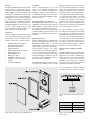
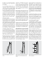
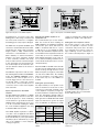
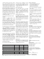
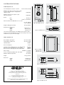
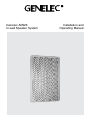
Genelec AIW26
In-wall Speaker System
Installation and
Operating Manual
General
Installation
The Genelec AIW26 Active In-wall speaker
system consists of a bass reflex type twoway speaker and a matched remote amplifier
module, RAM1. It has been designed to the
same rigorous standards as Genelec’s highperformance HT series active Home Theater
loudspeakers. No other in-wall loudspeaker
can match the low distortion, neutrality and
high sound pressure capability of Genelec
AIW26. The AIW26 can be used in the most
demanding applications, like the main L-CR array of a Home Theater system, critical
Stereo listening or rear/side channels of a
large, state-of-the-art Home Theater.
Genelec recommends that you use the
services of an authorized installation specialist or other competent and experienced
installation company for the installation of
the AIW26 system. Ask your local Genelec
dealer for recommended installation companies in your region.
Unpacking
A Genelec AIW26 set includes the following
items. Check that nothing is missing or damaged in transit. If there is a problem with the
product, contact your local Genelec dealer.
•
•
•
•
•
•
•
•
•
AIW26 loudspeaker unit with two
mounting brackets attached.
Grill frame and grill insert
(packed separately)
AIW26 cardboard cut-out template
RAM1 amplifier unit
Cable binding post tool
Mains power cable
Six M6x60 Pozidrive 3 screws
Plexiglass cover for the control switches
This Operating Manual
Matching speakers and amplifiers
Each AIW26 speaker unit has been factory
calibrated for optimum performance with the
RAM1 amplifier it is shipped with. Never mix
these matched amplifier-speaker systems in
the installation process. The matching units
are marked with the same ID number on the
reflex port of the AIW26 and the top panel of
the RAM1.
Speaker placement
Genelec AIW26 speakers are equipped with
Genelec’s proprietary Directivity Control
Waveguide™ (DCW™). One of the main
characteristics of the DCW technology is
that the speakers give a very even and consistent frequency response over a larger
listening area than conventional loudspeakers. A secondary function of the DCW™ is
to reduce the off-axis radiated sound energy,
thereby minimizing the reflections from the
side walls, floor and ceiling. This results in a
precise and stable sound image
If the AIW26 speakers are used in an application where their capability for precise sound
imaging is needed, such as the front channels of a Surround Sound system or a Stereo
system, we recommend that the speakers are
placed as far away from corners or other walls
and reflective surfaces as possible. The speakers should be placed symmetrically in relation
to the listening position and there should be
no obstructions between the speaker and
the listener. This guarantees clear dialogue
in films and a good stereo image with music.
Figure 2 shows a Left-Center-Right arrangement that works well both as Surround Sound
front channels and as a Stereo pair.
If you prefer a diffuse sound field, which is
less critical to the listening position and gives
only a vague sense of direction, for instance in
a rear/side channel setup in a Home Theater
system, you may actually benefit from the
acoustical reflections from nearby boundaries. In this case, place the speakers close to
the ceiling or another wall, or have them face
away from the listening position, so that the
proportion of reflected sound increases.
Choosing and installing the speaker
cables
The RAM1 amplifier unit has separate power
amplifiers for the tweeter and woofer. Accordingly, there are two pairs of binding posts,
white (-) and red (+) for the tweeter and black
(-) and grey (+) for the woofer. Be sure to
maintain correct polarity when connecting
the speaker cables and be extra careful not
to mix the tweeter and woofer cables
Use a good quality 4-conductor cable and
make the cable runs as short as possible.
Figure 2. Symmetrical L-C-R speaker installation
Cable gauge
30 m (100 ft)
2
40 m (131 ft)
2
60 m (200 ft)
2,0 mm (14 AWG)
3,3 mm (12 AWG)
5,3 mm (10 AWG)
Figure 1. Main components of the AIW26 system.
Max. length
2
Table 1. Recommended maximum lengths for
speaker cables.
See Table 1 for recommended cable gauges.
The binding posts accept a cable up to 6
mm2 (9 gauge).
If you are installing the AIW26 system to an
existing wall, examine the walls thoroughly
for the shortest and least obstructed cable
route. Be careful to avoid cutting or drilling
into electrical wires, ventilation or water pipes.
These are often visible in the attic, basement
or crawl space below the floor. All of this is
of course much easier when the installation
takes place in an unfinished wall where the
wall structure is still open. In both cases it is
a good idea to route the speaker cables away
from electric, video or phone cables, which
might induce hum into the speaker system.
Painting the speakers
The speaker grill frame and the metal mesh
part of the grill insert can be spray painted
to match the wall colour. Do not paint the
speaker cabinet itself, or try to paint the grill
frame or grill insert while they are attached
to the speaker. Remove the metal mesh from
the grill insert to avoid clogging the grill insert
cloth with paint. Paint the grill frame and
metal mesh separately with a thin spray. Do
not use brushes or rollers. Be very careful
not to clog the holes on the mesh with paint.
Installing the AIW26 speaker unit
Use the cardboard wall cut-out template to
find the location for the AIW26. The template
also shows the position of the speaker drivers, so you can easily find the placement that
brings them to the optimum position as outlined in chapter “Speaker placement”.
Examine the wall structure carefully to find a
clearly unobstructed location for the speaker.
The speaker cabinet requires a minimum of
88 millimeters (31/2”) of free depth behind
the sheetrock. Keep in mind that the mount-
Figure 3. Lift the AIW26’s top end into the
cut-out
ing brackets of the AIW26 need a clearance
inside the wall of at least 125 millimeters
(5”) above the top edge of the hole and 65
mm (29/16”) below the lower edge. Also note
that the grill frame is wider and taller than
the hole and requires about 30 millimeters
(13/16”) of smooth wall surface around all
sides of the hole.
When you have found a good location, check
that the template is level and trace the hole
onto the wall with a pencil along the outline
of the template. If you are not sure that the
chosen part of wall is free from obstructions,
you can start by making a smaller hole at the
center of the marked area through which you
can probe the inside of the wall. Use a drywall saw and make the first cut at a 45° angle
toward the center of the hole so you can put
the cut piece back in if the location is unsuitable. If you find no obstructions, you can
make the final cut along the marked lines.
If you have already connected the RAM1
amplifier units to the system, select the
speaker that has the same ID number as the
amplifier it will be driven by. Check the polarity
of the speaker cables and attach the cables
to the binding posts of the AIW26 speaker.
Lift the AIW26 into the hole top end (cable
binding posts) first (see Figure 3) and push
the lower end of the speaker onto the edge
of the hole. Push both mounting brackets
fully up and hold them there as you push the
lower half of the speaker into the wall (see
Figure 4). When the speaker is in the correct
position, pull the mounting brackets down. If
the wall cavity is deeper than 95 mm (33/4”),
the speaker can drop into it. This can be
avoided by mounting the speaker with the
grill frame loosely attached. Screw the frame
screws only half way in to allow some movement while installing the speaker.
Figure 4. Lift the mounting brackets up and
push the lower end of the speaker into the
cut-out
Attach the grill frame to the speaker with six
M6x60 Phillips screws provided with the kit
(see Figure 5). As you tighten the screws
evenly, the sheetrock will be clamped
between the ends of the mounting brackets
and the grill frame and the speaker will be
firmly attached to the wall. NOTE! Overtightening the screws will bend and damage the
grill frame. Keep a close look on the frame
as you tighten the screws and stop when you
see the metal base of the frame starting to
bend.
The grill insert has magnets on one side to
hold it onto the speaker’s grill frame. Attach
the insert on the speaker so that its crosspiece does not cover the drivers. Be very
careful not to dent the grill frame if you have
to remove the grill insert. Use a wide piece of
wood or plastic to wedge the insert out.
Connecting the RAM1 amplifier
The RAM1 amplifier is designed to be connected to a line level output of a preamplifier,
Surround Sound processor or other low level
source. NOTE! Never connect the RAM1 to
a speaker level output of a power amplifier!
Before making the connections, check that
the voltage selector on the amplifier’s back
panel is set to the correct voltage and the
power on all components is turned off.
Start by connecting the speaker cables to the
amplifier’s binding posts (see Fig. 7). Check
that the amplifier’s serial number matches
that of the AIW26 speaker unit which it
will power. The number can be found on a
sticker on the speaker’s reflex port and on
the amplifier’s top cover. If the speakers are
not yet installed, make a note of which amplifier is connected to each channel so you can
find the correct AIW26 speaker unit for every
amplifier. Check the cable polarity and use
the provided cable binding post tool to tighten
Figure 5. Pull the mounting brackets down and
attach the grill frame
Figure 7. Rear panel of the RAM1 amplifier
Figure 6. Front panel of the RAM1 amplifier
the binding posts. If you have lost the cable
binding post tool then a large screwdriver will
also work, but be careful not to overtighten
the binding posts as they may be damaged.
The RAM1 has two parallel 10 kOhm input
connectors: a balanced XLR and an unbalanced RCA. For longer cable connection
lengths (>10m or >30ft) a balanced line
connection is recommended as it offers
better immunity to external interference.
However, the RCA connection method
is more commonly available and usually
works as well for shorter connection lengths
in less electrically noisy environments. Do
not use both inputs at the same time. Consult your Genelec dealer for the choice of
signal cables.
The RAM1 has a provision for remote controlled switching between “ON” and “STANDBY”
modes. The “REMOTE CONTROL” connector block has two connector pairs: 1-2 for a
12 V DC trigger remote control and 3-4 for
an external switch or relay type (contact
closure) remote control (see Table 2). Do not
connect two remote controls to the amplifier
at the same time.
Space requirement for the RAM1
amplifier
The dual 120 W power amplifiers of a RAM1
unit generate a large amount of heat when
used at full power. To avoid overheating,
ensure that there is good airflow around the
amplifier and no external heat sources close
to it. We recommend installing the RAM1
into a well ventilated equipment rack using
its dedicated RM1 rack mount kit.
If the RAM1 amplifier is placed in a cabinet,
on a shelf or into an equipment rack without
its dedicated RM1 rack mount kit, there must
be at least 100 mm (4”) of free space behind,
150 mm (6”) above and 50 mm (2”) on both
sides of the amplifier to ensure adequate
cooling (see figure 8).
Mounting the RAM1 amplifier to an
equipment rack
We recommend that you use the Genelec
RM1 rack mount kit when installing the
RAM1 amplifier in an equipment rack. Make
sure that the space above and below the
RAM1 is uncluttered and there is a space
of 100 mm (4”) or more behind the amplifier. The space behind the amplifier must be
well ventilated. If the temperature inside the
rack is likely to rise close to RAM1’s maximum ambient temperature of 35° C (95° F),
we recommend installing ventilation fans to
ensure that the thermal protection is not activated prematurely.
(1.22V) is needed in this setting. Most preamplifiers are capable of this output level.
Setting the room response controls
The acoustic response of the system may
have to be adjusted to match the acoustic
environment and personal taste. See Table
3 for suggested room response control settings in differing acoustic environments. If
the sound is found subjectively too bright, set
Attach the RAM1 to the RM1 rack mount with
two M3 screws provided with the rack mount
kit. The screws go through the holes on the
RM1’s shelf plate (see Figure 9 ). Each RM1
can take three RAM1 units. Two blanking
plates are provided to cover empty spaces
in the rack if only one or two RAM1’s are
installed.
Setting the input sensitivity
The input sensitivity of each speaker can be
made to match that of the decoder or other
source by use of the input sensitivity control
on the amplifier’s front panel (see figure 6).
A small screwdriver is needed for the adjustment. The manufacturer default setting for
this control is -6 dBu (0.389V, fully clockwise)
which gives SPL of 100 dB @1m with -6 dBu
input level. Note that to get the full output
level of 110 dB SPL, an input level of +4 dBu
Remote
control type
12 V DC
remote
control
External
switch or
relay
Pole or
contact
Figure 8. Minimum space requirement of
the RAM1 amplifier when not installed with
Genelec RM1 rack mount.
Connect to
remote control
input pin no.
+
1
-
2
Contact 1
3
Contact 2
4
Connect only one remote control unit at a time
Table 2. Remote control connectors on the
RAM1.
Figure 9. Attaching the RAM1 to Genelec RM1
rack mount
‘treble tilt’ to -2 dB, if too bass heavy, set ‘bass
tilt’ to -2 dB. The adjustment is done by setting the three groups of room response control
switches ‘treble tilt’, ‘bass tilt’ and ‘bass roll-off’
on the front panel of the amplifier. The manufacturer default settings for all controls are ‘All
Off’ to give a flat response in half space, i.e.
when the speaker has been installed in a wall.
Always start adjustment by setting all switches
to the ‘OFF’ position. Then set only one switch
within each group to the ‘ON’ position to select
the desired response curve. The switches are
not cumulative. If more than one switch is set
to ‘ON’ (within one switch group) the attenuation value is not accurate.
Using Autostart and Remote control
functions
In daily use, the RAM1 amplifier can be
switched to “STANDBY” mode to save
energy by activating the signal sensing
Autostart function or by using a remote control unit (not included in the AIW26 system).
If the system is left unused for several days,
we recommend that you power it down using
the RAM1’s main power switch or a central
power switch if one has been installed.
The Autostart function is activated by turning
switch 4 (AUTOSTART) on the first switch
group to “ON”. Autostart turns the amplifier to
“STANDBY” mode if there is no signal present
for about 30 minutes. When the signal returns
the amplifier switches on immediately and
the speaker functions normally.
If you are using a remote control to switch the
RAM1 between “STANDBY” or “ON” modes
(see chapter “Connecting the RAM1 amplifier”), turn switch 3 (REMOTE CONTROL), on
the first switch group to “ON”. This activates
the remote control function. In this setting
the remote control will override the Autostart
function. If you want to use Autostart, turn the
“REMOTE CONTROL” switch to “OFF”.
Protecting the settings
The control group of the RAM1 can be cov-
ered with a piece of plexiglass to protect
the settings. Attach the plexiglass over the
switch groups with two Phillips screws when
you have completed the adjustments. Do not
overtighten the screws.
Status indicator LED
The status indicator LED on the RAM1
changes colour to indicate amplifier status.
If the LED is yellow, it indicates that the
amplifier is in “STANDBY” mode. When the
amplifier is switched to “ON” mode, the LED
changes to green colour.
Automatic protection circuits
The AIW26 system has protection circuits
against speaker driver thermal overload and
amplifier overheating. The protection system
resets automatically so the user only has to
turn the input level down to ensure that it
does not reactivate.
Driver thermal overload protection protects
the drivers from damage caused by prolonged overdriving with excessively high or
distorted signal. The circuit automatically
reduces the volume of the channel that is
being overloaded. To avoid this, lower the
listening volume if the sound becomes harsh
and distorted at high sound pressure levels.
Amplifier thermal protection turns the amplifier to “STANDBY” mode if the amplifier overheats. Let the amplifier cool down and check
that there is sufficient clearance around the
amplifier for cooling (see chapters “Space
requirement for the RAM1 amplifier” and
“Mounting the RAM1 amplifier to an equipment rack” above). If the problem persists,
consult your Genelec dealer or Home Theater
Installation company for an improved cooling
solution for your equipment cabinet or rack.
Maintenance
There are no user serviceable parts within
the loudspeaker or the amplifier. Any maintenance or repair should only be undertaken
by qualified service personnel.
Bass Roll-Off
Bass Tilt
Treble Tilt
ALL OFF
ALL OFF
ALL OFF
Well damped (dead sounding) room
0 dB
0 dB
0 dB
Normal room
0 dB
0 dB
-2 dB
Highly reflective (live sounding) room
0 dB
-2 dB
-4 dB
Half space factory default calibration setting
Safety considerations
•
Servicing and adjustment must only
be performed by qualified service
personnel. The loudspeaker or
amplifier must not be opened.
•
•
Do not use this product with an unearthed
mains cable as this may compromise
electrical safety.
Do not expose the loudspeaker or the amplifier to water or moisture. Do not place any
objects filled with liquid, such as vases, on
or near them.
• Do not place naked flame sources like lighted
candles on or near the loudspeaker or the
amplifier.
• This loudspeaker is capable of producing
sound pressure levels in excess of 85 dB,
which may cause permanent hearing
damage.
• Free flow of airaround the amplifier is necessary to maintain sufficient cooling. Do not
obstruct airflow around the amplifier.
• Note that the amplifier is not completely disconnected from the AC mains service unless
the mains power cord is removed from the
amplifier or the mains outlet.
WARNING!
This equipment is capable of delivering Sound
Pressure Levels in excess of 85dB, which
may cause permanent hearing damage.
Guarantee
This product is supplied with a two year guarantee against manufacturing faults or defects
that might alter the performance of the unit.
Refer to supplier for full sales and guarantee
terms.
EC Declaration of Conformity
This is to certify that Genelec AIW26 I-wall
Speaker System conforms to the following
standards:
Safety:
EN 60065 / IEC 60065:1998 7th Edition
EMC:
EN 55013: (2001)
EN 55020: (1994), A11: (1996), A12: (1999),
A13: (1999), A14: (1999)
EN 61000-3-2 (2000)
EN 61000-3-3 (1995)
The product herewith complies with the
requirements of The Low Voltage Directive
73/23/EEC, EMC Directive 89/336/EEC and
93/68/EEC
Additional settings to compensate for the loudspeaker positioning within the room:
In a double corner (wall/wall or wall/ceiling)
-2 dB
-2 dB
0 dB
In a triple corner (wall/wall/ceiling)
-4 dB
-4 dB
0 dB
If the speaker is positioned behind a perforated screen, add +2 dB to the Treble Tilt setting to compensate
Table 3. Suggested room response control settings for differing acoustical environments
Signed:
Ilpo Martikainen
Position: Managing Director
Date:
25-November-2004
SYSTEM SPECIFICATIONS
AIW26 Speaker unit
Free field frequency response of system: 45 Hz...21kHz (±2,5 dB)
Maximum short time sine wave acoustic output
at 1 m on axis in half space, averaged from
100 Hz to 3 kHz:
>110 dB SPL
Maximum peak acoustic output for a pair
with music material:
>120 dB SPL
Drivers
Bass: Treble:
182 mm (7”)
19 mm (3/4”) metal dome
Harmonic distortion at 90 dB SPL @ 1 m on axis:
Weight including grill assembly:
< 3% (50...200 Hz)
< 0,5% (>200 Hz)
Figure 10. AIW26 front view
Figure 11. AIW26 side view
10,7 kg (23,6 lbs)
Required cut-out dimensions
Height:
545 mm (211/2”)*
Width:
334 mm (131/8”)
Depth:
88 mm (31/2”)**
Figure 12. AIW26 top view
*Note: The mounting brackets of the AIW26 need a clearance inside
the wall of at least 125 millimeters (5”) above the top edge of the cut-out
and 65 mm (29/16”) below the lower edge.
15 (5/8")
374 (14 3/4")
RAM1 Amplifier unit
Bass amplifier output power:
Treble amplifier output power:
Input impedance:
Short term 120 W
Short term 120 W
10 kOhm
Crossover frequency:
Treble tilt control in 2dB steps from +2 to -4dB & MUTE:
Bass roll-off control in 2 dB steps from 0 to -6 dB:
Bass tilt control in 2 dB steps from 0 to -6 dB & MUTE:
@15 kHz
@50 Hz
@100 Hz
Mains voltage:
100/200V or 115/230V
Power consumption (Standby / Idle / Full output): 5/10/200 W
Maximum ambient temperature
Weight:
Dimensions
Height:
Width:
Depth:
598
(23 1/2")
3.5 kHz
Figure 13. AIW26
grill frame side
and front views
35°C (95°F)
4,6 kg (10,1 lbs)
130 mm (51/8”)
145 mm (53/4”)
309 mm (123/16”)
Figure 14. RAM1 side view
Genelec Oy
Olvitie 5, FIN - 74100 IISALMI, FINLAND
Phone: +358 - 17 - 83881, Fax: +358 - 17 - 812 267
E-mail: [email protected], Web: www.genelec.com
Genelec Inc
7 Tech Circle, Natick, MA 01760, USA
Phone: +1 - 508 - 652 - 0900, Fax:+1 - 508 - 652 - 0909
E-mail: [email protected]
Genelec Document DR0005001b Copyright Genelec Oy 11.2006
All data subject to change without prior notice.
Figure 15. RAM1 top view