1
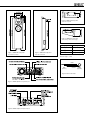
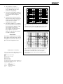
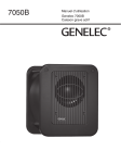
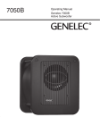
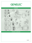
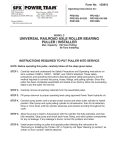
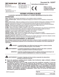
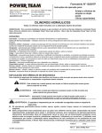
AOW312B
Operating Manual
Genelec AOW312B
Active On-Wall Loudspeaker
Genelec AOW312B Active On-Wall Loudspeaker
System
The Genelec AOW312B is a three-way active
loudspeaker system designed for medium
sized, high quality home theater applications.
This system excels as side or rear channels
when mounted on-wall. It also offers minimum intrusion into designed spaces while
providing high sound pressure levels required
when employing Genelec’s large three-way
systems for left, center, and right positions
and HTS6 series subwoofer in rooms greater
than 260 m3 / 9000 cu. ft.
Designed as an active loudspeaker system,
each AOW312B system contains an individually matched RAM4 amplifier unit with multiple power amplifiers, active crossover filters
and protection circuitry.
The unique Directivity Control Waveguide™
(DCW™) technology developed by Genelec
provides extremely stable and accurate imaging and frequency balance even in difficult
acoustic environments. Furthermore, versatile and precise crossover controls allow for
accurate matching of the loudspeakers systems to different room acoustic conditions.
The AOW312B is fixed to the wall via
unique mounting brackets which isolate and
suspend the enclosure vertically. The brackets also allow the enclosure to be mounted
with a ±15 degree angle offset to the wall to
facilitate energy focus at desired listening
locations.
All electronics are factory calibrated as
a single unit, thus eliminating the effects of
component tolerances and ensuring consistent quality and long term reliability.
Low frequencies are reproduced by a 305
mm (12”) bass driver with a low frequency
extension to 35 Hz. The 130 mm (5”) midrange cone and 25 mm (1”) HF driver are
loaded into the proprietary Directivity Control
Waveguide™.
The RAM4 amplifier unit contains an active
crossover, the ideal method for dividing an
input signal between the driver units, allowing the overall response of the system to
be optimized to an extent impossible with a
passive system. Variable input sensitivity as
well as a balanced XLR line level input connector provide easy connection and accurate
level matching to the preamplifier or surround
decoder. The bass, midrange and treble
amplifiers of the RAM4 produce 180 W for
the low frequency driver and 120 W each for
the mid-range and HF drivers.
The amplifiers are designed to operate at
very low THD and IM distortion values and
are capable of driving the AOW312B to peak
output levels in excess of 124 dB SPL at 2 m
with music material.
Like all Genelec HT models, the AOW312B
system incorporates special circuitry for driver
overload and amplifier thermal protection, as
well as an “Autostart” function for automatic
switching between “Standby” and “On” power
modes. A connector for 12 V trigger or external switch or relay type remote control facilitates central power mode switching.
The 3U RAM4 remote amplifier module
is ready to be installed into a 19” equipment rack. Neutrik Speakon connectors are
included to facilitate wiring and system connection. Signal cables are not provided with
the system. See section "Connections" below
for selecting signal cables.
Installation
Once unpacked, place the loudspeaker
enclosure upright in its required position,
taking note of the line of the acoustical axis
(see Figure 2). Attach the mounting brackets
to the wall with suitable screws for carrying
the loudspeaker's weight of 43 kgs (95 lbs).
The maximum tilt angle for the loudspeaker
enclosure is ±5 degrees. Do not install the
enclosure horizontally.
The mounting brackets are pre-drilled for
enclosure alignment angles of -15°, 0° and
+15°. If necessary, you can drill new holes to
the brackets for exact loudspeaker alignment.
The rubber isolators provided must be placed
between the brackets and loudspeaker enclosure.
It is recommended that the surroundings
of the loudspeaker are covered with about
10 cms (4") of rockwool or similar damping
material. If the loudspeaker is covered with
a cloth, it must be acoustically transparent
and a free space of at least 2 cm (3/4") left
between the front baffle and the cloth.The
reflex port of the loudspeaker enclosure is
located on the left side of the enclosure (see
Figure 2). The airflow from the port must not
be obstructed, and a free space of at least 5
cm (2") is required before the port.
The RAM4 amplifier is shipped with a pair
of rack ears to provide fitting into a 19" rack
and a set of feet for placement on a shelf or
table.
Sufficient cooling for the RAM4 amplifier
must be ensured. The cooling fan on the
amplifier back panel draws air through the
filter on the left side panel and blows the
warmed air to the space behind the amplifier. The airflow must not be obstructed. Note
also that the space behind the amplifier must
either be ventilated or sufficiently large to
dissipate heat so that the ambient temperature does not rise above 35 degrees Celsius
(95°F).
Connections
Each loudspeaker is delivered with two
Speakon 8-pole cable connectors. There is
one 8-pole Speakon output marked LOUDSPEAKER CONNECTOR on the amplifier
and two inputs (one on each side) on the
loudspeaker enclosure. Use only one of these
inputs at any time. The inputs may not be
used for daisy-chaining several loudspeakers
or connecting two amplifiers to a single loudspeaker. The 4-pole Speakon output (LED
CONNECTOR) on the amplifier is not used
with the AOW312B.
Measure the required length of 8 pole cable
and secure the connectors on it pin to pin.
See Table 1 below for recommended cable
thicknesses. The whole cable should have
an outside diameter of 8 to 20 mm (5/16" to
13/16") to fit in the Speakon connector.
Alternatively, pre-terminated lengths of
cable are available from Genelec.
Be sure not to mix the amplifier/loudspeaker pairs when installing multiple loudspeakers at the same time. Each amplifier and
loudspeaker packed together are calibrated
together for optimal performance and marked
with the same identification number.
Before connecting up, ensure that the mains
switch is off. Check that the mains voltage
selector on the amplifier back panel is correctly
set to your local voltage. Audio input is made
via a 10 kOhm balanced XLR connector, but
unbalanced leads may be used as long as pin
3 is grounded to pin 1 of the XLR (see Figure
7). Once connection has been made, the loudspeakers are ready to be powered-up.
Access to the
front panel controls
The decorative front panel of the RAM4
amplifier is held in place by guide pins and
two magnets. To remove the panel, pull it
straight out.
Setting the input sensitivity
Adjustment of the input sensitivity of each
RAM4 amplifier can be made to match the
output of the decoder or other source, by
use of the input sensitivity control on the
amplifier front panel. A small screwdriver is
needed for the adjustment. The manufacturer default setting for this control is -6 dBu
(fully clockwise) which gives an SPL of 100
dB @1m with a -6 dBu input level. To get the
full output level from the AOW312B an input
level of +10 dBu is needed at this setting.
Autostart and remote control
The RAM4 amplifier unit is equipped with
an “Autostart” function, which automatically turns the amplifier to “standby” mode
if an input signal has not been detected
for approximately thirty minutes, and back
to “on” mode when the signal returns. The
function can be deactivated by turning the
“AUTOSTART” dip switch on the back panel
of the amplifier to “OFF”.
The amplifier mode can also be switched by
a remote control unit connected to the respective inputs on the amplifier back panel. Two
pairs of connectors are provided, 1 and 2 for a
12 V DC type remote control, and 3 and 4 for
an external switch or relay type control. Do
not connect two remote controls to the loudspeaker at the same time. Activate the function by turning the "REMOTE CONTROL" dip
switch to "ON". Note that the remote control
function overrides the “AUTOSTART” dip
switch function.
Setting the tone controls
The acoustic response of the system should
be adjusted to match the acoustic environment. The adjustment is done by setting the
five tone control switch groups ‘bass tilt’, ‘bass
roll-off’, ‘bass level’, ‘mid level’ and ‘treble level’
on the amplifier front panel. The manufacturer’s default settings for these controls are ‘All
Off’ to give a flat anechoic response. Figure 8
shows the effect of the controls on the anechoic response. Always start adjustment by
setting all switches to the ‘OFF’ position. Then
set only one switch per group to the ‘ON’ position to select the response curve required. If
more than one switch is set to ‘ON’ (within
one switch group) the attenuation value is no
longer accurate.
Maintenance
The air filter on the left side of the RAM4
amplifier must be cleaned every six months.
Remove the decorative front plate and pull
the filter out. Check the filter and replace it
with a new one if any damage or brittleness
can be found. If the filter is in a good condition, carefully clean it with compressed air.
No other serviceable parts are to be found
within the loudspeaker enclosure or the
amplifier unit. Any maintenance or repair
should only be undertaken by qualified service personnel.
Safety considerations
Although the AOW312B loudspeaker and
RAM4 amplifier have been designed in
accordance with international safety standards, to ensure safe operation and to maintain safe operating conditions, the following
warnings and cautions must be observed:
1. 2. Servicing and adjustment must only
be performed by qualified service
personnel. The amplifier must not be
opened.
Do not use the amplifier with an
unearthed mains cable or unearthed
mains connection as this may lead to
personal injury.
Figure 3. AOW312B loudspeaker
enclosure top view.
Figure 4. AOW312B loudspeaker
enclosure top view at 15° angle.
Cable gauge
Max. length
2,0 mm2 (14 AWG)
30 m (100 ft)
3,3
Figure 1. AOW312B loudspeaker
enclosure front view.
Figure 2. AOW312B loudspeaker
enclosure side view.
mm2
(12 AWG)
40 m (130 ft)
5,3 mm2 (10 AWG)
60 m (200 ft)
Table 1. Recommended cable thicknesses for
different lengths of cable
Cable
RCA
(Source)
Screen
Figure7. RCA to XLR cable
Figure 5. RAM4 amplifier rear panel layout.
Figure 6. RAM4 amplifier front panel layout.
XLR
(Speaker)
3.
4.
5.
6. This loudspeaker is capable of
producing sound pressure levels in
excess of 85 dB, which may cause
permanent hearing damage.
A free flow of air through the amplifier is
necessary to maintain sufficient cooling.
Do not obstruct airflow through the
amplifier
To prevent fire or electric shock, do not
expose the unit to water or moisture. Do
not place any objects filled with liquid,
such as vases on or near the
loudspeaker or the amplifier.
Note that the amplifier is not completely
disconnected from the AC mains service
unless mains plug or appliance coupler
of the amplifier is disconnected
from the mains outlet. Ensure that the
plug or appliance coupler of the
amplifier is readily operable and easily
accessible for doing this.
AUDIO PRECISION AOW312 ANEC
LEVEL(dBr)
vs
FREQ(Hz)
04 AUG 06
90
85
80
BASS TILT
90
85
80
BASS LEVEL
90
TREBLE LEVEL
85
80
BASS ROLL-OFF
20
MIDRANGE LEVEL
100
1k
10k
20k
Figure 8: The curves above show the effect of the ‘bass’, ‘mid’ and
‘treble’ level controls, and the ‘bass tilt’ and ‘bass roll-off’ controls
on the free field response of the AOW312B, measured at 2 m.
AUDIO PRECISION AOW312 ANEC
100
LEVEL(dBr)
vs
FREQ(Hz)
04 AUG 06
95
Guarantee
This product is supplied with a two year guarantee against manufacturing faults or defects
that might alter its performance. Refer to supplier for full sales and guarantee terms.
0
90
15
85
80
30
45
75
70
100
65
95
60
90
85
80
20
EC Declaration of Conformity
This is to certify that the Genelec AOW312B Active On-Wall
Loudspeaker conforms to the following standards:
Safety:
EN / IEC 60065:1998 6th Edition
EMC:
EN 55020 : 2002 + A1 : 2003
EN 55013: (2001)
EN 61000-3-2 (2000)
EN 61000-3-3 (1995)
The product herewith complies with the requirements of
The Low Voltage Directive 73/23/EEC, EMC Directive
89/336/EEC and 93/68/EEC
Signed:
Position:
Date:
Ilpo Martikainen
Chairman of the Board
12-May-2008
100
1k
10k
Figure 9: The upper curve group shows the horizontal directivity
characteristics of the AOW312B in its vertical configuration
measured at 2 m. The lower curve is a 1/6 octave power
response measurement, derived from 144 individual directivity
measurements.
20k
AOW312B Operating Manual
system specifications
Amplifier Section
AOW312B
AOW312B
Lower cut-off frequency, -3 dB
Upper cut-off frequency, -3 dB
Free field frequency response of system
<35 Hz
>22 kHz
37 Hz - 21 kHz (±2.5 dB)
Bass amplifier short term output power
180 W (4 Ohm load)
Midrange amplifier short term output power
120 W (8 Ohm load)
Maximum short term sine wave acoustic output
on axis in half space, averaged from 100 Hz to
3 kHz
@ 1 m >116 dB SPL
Treble amplifier short term output power
120 W (8 Ohm load)
Maximum long term RMS acoustic output in same
conditions with IEC-weighted noise (limited by
driver unit protection circuit)
@ 1 m >107 dB SPL
Slew rate
80V/µs
Maximum peak acoustic output per pair in half
space with music material
@ 2 m >123 dB
Self generated noise level in free field @ 2 m
on axis
<15 dB (A weighted)
Amplifier system distortion at nominal output
THD
SMPTE-IM
CCIF-IM
DIM 100
<0.05%
<0.05%
<0.05%
<0.05%
Harmonic distortion at 95 dB SPL at 1 m on axis:
freq. <100 Hz <1%
freq. >100 Hz <0.5%
Signal to Noise ratio, referred to full output
Bass
Midrange
Treble
>100 dB
>100 dB
>100 dB
Mains voltage
100/200 V or 115/230 V
Voltage operating range
nominal ±10%
Power consumption
Idle
Full output
50 W
300 W
Drivers Bass
Midrange
Treble
Long term output power is limited by driver unit protection circuitry.
305 mm (12") cone
130 mm (5") cone
25 mm (1") metal dome
Weight
Loudspeaker
Amplifier
43 kg (95 lb)
12 kg (27 lb)
Loudspeaker dimensions
Height
Width
Depth
1500 mm (59 1/16")
400 mm (15 3/4")
175 mm (6 7/8")
Amplifier dimensions
Height
Width
Depth
133 mm (5 1/4") (3 U)
483 mm (19")
350 mm (13 4/5")*
*Note that the cable connectors require
additional >100 mm (4") space behind the
amplifier
crossover Section
AOW312B
Input connector XLR female
pin 1 gnd
pin 2 +
pin 3 -
Input impedance
10 kOhm
Input level for 100 dB SPL output @1 m
variable from +6 to -6 dBu
Input level for maximum short term output
variable from +22 to +10 dBu for 116 dB
SPL @1 m
Subsonic filter
18 dB/octave below 35 Hz
Ultrasonic filter
12 dB/octave above 25 kHz
Crossover frequency
Bass/Mid
Mid/Treble
420 Hz
3.2 kHz
Crossover acoustical slopes
18 - 24 dB/octave
Crossover level control operating range in
1 dB steps
Bass
Mid
Treble
from 0 to -6 dB
from 0 to -6 dB
from 0 to -6 dB
Bass roll-off control in 2 dB steps
from 0 to -8 dB @35 Hz
Bass tilt control in 2 dB steps
from 0 to -8 dB @80 Hz
The 'CAL' position is with all tone controls
set to 'off' and input sensitivity control to
maximum.
www.genelec.com
Genelec Document D0075R001a Copyright Genelec Oy 5.2008. All data subject to change without prior notice
International enquiries:
In the U.S. please contact:
In China please contact:
In Sweden please contact
Genelec, Olvitie 5
Genelec, Inc., 7 Tech Circle
Beijing Genelec Audio Co. Ltd.
Genelec Sverige
FIN-74100, Iisalmi, Finland
Natick, MA 01760, USA
Jianwai SOHO, Tower 12, Room 2306
Ellipsvägen 10B
Phone +358 17 83881
Phone +1 508 652 0900
39 East 3rd Ring Road
P.O. Box 5521, S-141 05 Huddinge
Fax +358 17 812 267
Fax +1 508 652 0909
Chaoyang District
Phone +46 8 449 5220
Email [email protected]
Email [email protected]
Beijing 100022, China
Fax +46 8 708 7071
Phone +86 0 5869 7915, Fax +86 10 5869 7914
Email [email protected]