1
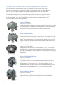
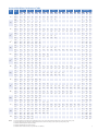
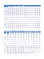
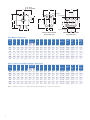
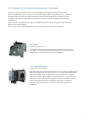
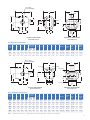
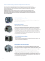
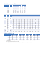
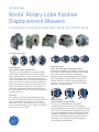
GE Oil & Gas
Roots* Rotary Lobe Positive
Displacement Blowers
Universal RAI* Series | RAM* Series | RCS* Series | DVJ and DPJ Series
Operating Principles
Bi-Lobe Principle
URAI, URAI-DSL, URAI-G, RAM, RCS Series
Two figure-eight lobe impellers mounted on parallel
shafts rotate in opposite directions. As each impeller
passes the blower inlet, it traps a finite volume of air and
carries it around the case to the blower outlet, where
the air is discharged. With constant speed operation, the
displaced volume is essentially the same regardless of
pressure, temperature or barometric pressure. Timing
gears control the relative position of the impellers to
each other and maintain small but finite clearances.
This allows operation without lubrication being required
inside the lobe cavity.
WHISPAIR* Principle
URAI-J, URAI-J DSL, RAM-J, RAM-GJ, RAM-VJ, RCS-J
Incoming air is trapped by the impellers. Simultaneously,
pressurized air (right) is being discharged. As the impeller
passes the wrap-around flange, the Whispair jet
equalizes pressure between trapped air and discharge
area, aiding impeller movement and reducing power.
Impellers move air into the discharge area. Backflow is
controlled, resulting in reduction of noise and pulsation
relative to conventional blowers.
Warranty
Proven designs, manufacturing and material provide
assurance for superior operation. Local, factory trained,
service centers offer timely response to your unique
needs. Roots products are sold subject to GE’s general
terms of sale and warranty policy; contact your nearest
GE office for more information.
DVJ/DPJ Principle
2504 DVJ, RAM DVJ, 721 DVJ, 406 DPJ
Incoming air is trapped between the impellers.
Simultaneously, pressurized air is being discharged.
As the impeller passes the jet plenum, cooled, pressurized
air flows into the space between the impeller and cylinder.
This cools the trapped air, helps control thermal growth
and allows higher pressure ratios. The trapped air is then
moved into the discharge flange. Backflow is reduced,
resulting in lower operating noise level and reduced
shock loading on the equipment.
Universal RAI Series Rotary Positive Displacement Blowers
All Universal RAI (URAI) series blowers are heavy duty rotary blowers in a compact, sturdy design
engineered for continuous duty and maximum reliability. These blowers have a time tested lubrication
system. GE’s exclusive “figure-8” gearbox design improves oil distribution to the timing gears and
lengthens bearing life.
This series features a grey iron casing, carburized and ground alloy steel spur timing gears secured to
steel shafts with a taper fit and locknut, and grey iron involute impellers. Oversized anti-friction bearings
are used, with a heavy duty cylindrical roller bearing at the drive shaft to withstand V-belt pull. Viton™
lip seals maintain proper lubricant at the bearings
Universal RAI Blower
Frame Sizes 22 thru 718
The standard URAI blower features convenient grease lubrication on the drive end.
The feet permit easy in-field adaptation to either vertical or horizontal installation
requirements and any of four drive shaft positions – top, bottom, right or left hand.
All frame sizes are center-timed to allow for rotation in either direction.
Universal RAI DSL Blower
Frame Sizes 32 thru 615
This URAI blower features Dual Splash Lubrication (DSL). There is splash lubrication
at the gear end and the drive end. The drive end has two shaft-mounted slingers
and the gear end features GE’s exclusive “figure-eight” gearbox design that work
together to improve oil distribution and to maximize gear and bearing life. The oil
reservoirs feature sight glasses for accurate oil level confirmation.
Universal RAI-G Gas Blower
Frame Sizes 32GJ thru 615GJ
URAI gas blowers feature mechanical seals and Viton™ o-rings. The seal system is
designed to meet or exceed gas industry safety standards, including provisions for
purge gas in the headplates. The URAI gas blower uses detachable steel mounting
feet for adaptation of drive shaft position to meet vertical or horizontal installation
requirements.
Universal RAI-J WHISPAIR Blower
Frame Sizes 33J thru 56J
GE refined the standard URAI line using computer-aided design techniques
to incorporate the Roots exclusive WHISPAIR jet. The WHISPAIR jet uses shock
suppression techniques for noise and pulsation reduction. This exclusive
WHISPAIR feature can reduce noise 3-5 dB on typical installations. Like the
standard URAI blower, the URAI-J features universal detachable steel mounting
feet to permit easy in-field adaptation to any of four positions and grease
lubrication on the drive end.
Universal RAI-J DSL Blower
Frame Sizes 33J thru 56J
This URAI blower combines the WHISPAIR design with the dual splash lubrication
feature to offer the longest life and quietest performance of the URAI series.
2
Universal RAI Blower Performance Table
Frame
Size
22
24
323,5
333,4,5
363,4,5
423,5
453,4,5
473,4,5
533,5
563,4,5
593,5
653,5
3,5
68
6153,5
76
711
718
Notes:
1 psi
6 psi
7 psi
10 psi
12 psi
13 psi
14 psi
15 psi
Max Vacuum
Speed
RPM
CFM
BHP
1160
10
0.1
3600
49
0.3
38
1.6
36
1.8
32
2.6
29
5275
76
0.5
64
2.4
63
2.7
59
3.8
56
1160
24
0.2
3600
102
0.6
83
3.1
81
3.6
5275
156
0.9
137
4.6
135
5.4
1160
40
0.2
21
1.4
19
1.6
2800
113
0.6
95
3.4
93
3.9
86
5.6
82
6.7
81
7.2
79
7.8
77
8.3
15
78
4.1
3600
149
0.9
131
4.4
129
5.2
122
7.3
118
8.7
117
9.4
115
10.1
113
10.8
16
110
5.3
CFM
BHP
CFM
BHP
CFM
BHP
CFM
BHP
CFM
BHP
CFM
BHP
CFM
BHP
"HGV
CFM
BHP
4
6
0.2
3.1
14
28
1.8
4.6
15
53
2.8
6
12
0.5
14
69
3.5
15
119
5.5
10
18
1.1
1160
55
0.3
31
1.9
28
2.2
2800
156
0.9
132
4.6
129
5.4
120
7.7
116
9.2
10
27
1.5
14
113
5.2
3600
205
1.2
181
6.1
178
7
170
9.9
165
11.9
1160
95
0.5
61
3.1
57
3.6
15
159
7.3
10
55
2.5
2800
262
1.5
229
7.7
224
8.9
12
213
7.5
3600
344
2.1
310
10.1
306
11.7
15
278
12.1
860
38
0.2
18
1.4
15
1.6
1760
92
0.5
72
2.8
69
3.3
62
4.7
58
5.6
3600
204
1.4
183
6.1
181
7.1
173
9.9
169
11.8
860
79
0.5
42
2.7
37
3.2
1760
188
1
151
5.7
146
6.6
133
9.4
12
134
5.5
3600
410
2.7
374
12.2
369
14.1
356
19.8
16
332
15.4
2.4
167
12.8
165
13.7
163
14.7
8
19
0.9
14
56
3.2
16
160
7.7
8
46
1.8
860
105
0.6
59
3.6
53
4.2
8
63
1760
249
1.3
203
7.5
196
8.7
12
181
7.3
3600
542
3.5
496
16.1
490
18.6
15
452
19.1
700
72
0.4
42
2.4
38
2.8
1760
211
1.2
181
6.3
177
7.3
167
10.3
160
12.3
157
13.3
155
14.4
310
17.2
304
20.5
301
22.1
298
23.8
2850
355
2.5
325
10.7
321
12.3
700
123
0.7
78
4.1
72
4.7
1760
358
2
312
10.5
306
12.2
290
17.3
280
20.6
276
2850
598
4
553
17.7
547
20.5
531
28.7
521
34.2
517
17.8
700
187
1
130
5.9
1760
529
2.9
472
15.3
464
295
25.4
10
36
2
14
158
7.1
13.4
16
291
10
70
3.3
22.3
14
276
11.8
37
16
501
22.4
2850
881
5.9
824
26
816
30
700
140
0.8
93
4.5
86
5.3
70
7.5
1760
400
2.4
353
11.9
347
13.8
330
19.4
320
23.2
316
25.1
311
27
307
28.9
2350
546
3.8
499
16.4
492
19
475
26.5
466
31.6
461
34.1
457
36.6
452
39.1
700
224
1.2
149
7.3
139
8.5
1760
643
3.7
567
18.9
557
21.9
530
31
515
37
507
40.1
500
2350
876
5.6
801
25.9
790
29.9
763
42.1
748
50.2
740
54.2
733
700
420
2.3
279
13.6
260
1760
1205
6.6
1063
34.9
2350
1641
9.7
1500
575
192
1.1
134
1400
527
3
2050
790
5.3
575
362
1.9
8
135
3.9
12
445
14.9
15
770
30.8
12
71
4.4
16
300
15.2
16
445
25.6
10
135
5.9
43.1
15
495
22.7
58.3
16
715
32.8
15.9
8
292
8.9
1044
40.6
12
997
33.9
47.6
1481
55.2
14
1389
53.4
6.1
126
7.1
105
10.2
12
117
6
468
15.4
460
17.8
439
25.3
427
30.2
421
32.7
415
35.1
410
37.6
16
413
19.7
731
23.4
723
27
702
37.9
690
45.1
684
48.7
679
52.4
673
56
16
674
29.5
271
11.1
258
13
226
18.6
12
228
10.9
1400
970
5.2
880
27.7
867
32.2
835
45.7
15
793
33.5
2050
1450
8.8
1359
41.8
1347
48.4
1315
68.2
16
1256
53.1
575
600
3.1
470
18.1
10
446
14.8
1400
1590
8.1
1460
44.8
12
1398
43.6
2050
2370
13.3
2240
66.9
12
2178
64.7
1. Pressure ratings based on inlet air at standard pressure of 14.7 psia, standard temperature of 68° F, and specific gravity of 1.0.
2. Vacuum ratings based on inlet air at standard temperature of 68° F, discharge of 30" Hg and specific gravity of 1.0.
3. Available with Dual Splash Lube (DSL) feature.
4. Available with Whispair Jet (URAI-J) feature.
5. Available with mechanical seals (see performance for URAI-G).
3
Universal RAI-G Blower Performance Table
Frame Speed
Size
RPM
32
33
36
42
45
47
1 psi
3 psi
5 psi
7 psi
CFM
11 psi
BHP
CFM
13 psi
CFM
BHP
CFM
BHP
1200
37
0.2
25
0.7
16
1.2
1800
64
0.4
52
1.1
43
1.8
36
2.5
2500
96
0.6
83
1.5
75
2.5
68
3.5
56
5.5
51
6.4
49
6.9
3600
145
0.9
133
2.3
124
3.7
117
5.2
106
8
101
9.4
99
10.1
1200
52
0.3
36
1
24
1.6
89
0.5
73
1.5
61
2.5
52
3.4
2500
132
0.8
116
2.1
105
3.5
96
4.8
81
3600
200
1.2
183
3.2
172
5.1
163
7
148
1200
91
0.6
68
1.6
53
2.7
40
1800
152
0.9
129
2.5
114
4.1
2500
224
1.3
201
3.5
185
5.7
3600
336
2.1
313
5.3
297
1200
54
0.3
40
1
1800
90
0.5
76
1.5
2500
132
0.8
118
3600
199
1.4
1200
111
1800
2500
CFM
BHP
CFM
15 psi
BHP
1800
BHP
14 psi
CFM
BHP
CFM
96
Max Vacuum
BHP
10.8
"HGV
CFM
BHP
8
15
0.9
10
35
1.7
13
56
3.2
16
93
5.7
8
23
1.3
10
51
2.4
7.5
13
80
5.3
10.9
15
137
7.3
3.8
8
50
2.1
101
5.7
10
99
4
172
7.9
13
150
7.2
8.5
285
11.7
15
248
12.1
30
1.6
22
2.2
1.3
67
2.4
59
3.4
46
5.3
2.1
109
3.4
101
4.8
88
7.4
83
8.7
80
9.4
78
185
3.3
175
5.2
168
7.1
155
10.9
149
12.8
147
13.7
144
0.7
86
1.9
69
3.2
55
184
1
159
2.9
142
4.8
269
1.6
244
4.2
227
6.9
3600
402
2.7
377
6.5
360
10.3
1200
149
0.9
117
2.5
96
4.2
78
5.9
8
92
3.3
1800
244
1.4
213
3.9
191
6.4
174
8.9
10
171
6.2
2500
356
2.1
325
5.6
303
9
285
12.5
13
255
11.3
3600
531
3.5
500
8.5
478
13.6
461
18.6
15
410
19.1
800
78
0.5
57
1.4
43
2.3
32
3.2
8
41
1.8
1400
157
0.9
136
2.5
122
4.1
111
5.7
10
109
4
1800
209
1.2
189
3.3
175
5.4
164
7.5
145
11.6
137
13.7
133
14.7
13
144
6.7
2850
348
2.5
327
5.8
313
9
302
12.3
283
18.9
275
22.1
272
23.8
16
262
13.4
8
29
10
58
2.4
10
13
88
4.3
14.7
16
140
7.7
4.5
8
67
2.5
128
6.7
10
126
4.7
213
9.5
13
189
8.6
346
14.1
16
297
15.4
92
9
53
56
59
65
68
615
Notes:
4
268
25.4
800
135
0.8
104
2.3
83
3.9
65
5.4
8
79
3
1400
267
1.5
236
4.2
215
6.9
198
9.6
170
15
157
17.7
10
195
6.7
1800
356
2.1
325
5.5
304
9
286
12.5
258
19.4
246
22.9
13
257
11.2
2850
588
4
557
9.5
536
15
518
20.5
490
31.5
478
37
15
468
21
800
205
1.2
167
3.4
140
5.7
118
7.9
8
136
4.4
1400
399
2.2
360
6.1
334
10.1
312
14
10
309
9.8
1800
528
3
490
8.1
463
13.2
441
18.2
13
404
16.5
2850
868
5.9
829
13.9
802
22
780
30
15
718
30.8
700
129
0.8
97
2.3
75
3.8
57
5.3
1400
301
1.8
269
4.8
247
7.8
229
10.8
200
16.8
1800
399
2.5
367
6.4
345
10.2
327
14.1
298
21.8
285
25.7
280
27.6
274
29.5
13
297
12.7
2350
534
3.8
503
8.9
481
13.9
463
19
433
29
421
34.1
415
36.6
409
39.1
16
400
20.6
4.8
187
19.8
181
21.3
175
22.8
8
71
3
10
226
7.5
700
206
1.2
155
3.7
120
6.1
91
8.5
8
115
1400
483
2.7
432
7.6
396
12.4
368
17.2
321
26.9
300
31.7
291
34.1
10
363
12
1800
641
3.8
590
10
554
16.2
526
22.4
479
34.8
458
41
449
44.1
13
477
20.2
2350
858
5.6
807
13.7
772
21.8
743
29.9
696
46.1
676
54.2
666
58.3
16
642
32.8
700
387
2.3
291
6.8
224
11.3
8
215
8.9
1400
905
5
809
14
742
23
689
32.1
10
681
22.4
1800
1201
6.7
1104
18.4
1038
30
985
41.6
12
922
34.7
2350
1608
9.7
1512
24.8
1445
40
1392
55.2
13
1300
49.7
1. Performance based on METHANE at standard pressure of 14.7 psia, standard temperature of 68° F, and specific gravity of 0.55.
2. For vacuum service consult factory or nearest Roots sales office.
Universal RAI Dimensions
1
Frame
Size
A
B
C
22
24
32
33
36
42
45
47
53
56
59
65
68
615
76
711
718
5.13
5.13
7.25
7.25
7.25
8.00
8.00
8.00
10.50
10.50
10.50
11.001
11.001
11.001
14.002
14.002
14.002
5.00
7.00
6.75
7.63
10.00
7.25
10.00
11.75
8.38
11.00
14.00
10.00
13.00
20.00
11.75
16.75
23.75
9.75
11.75
11.25
12.13
14.63
13.00
15.50
17.63
15.38
18.00
21.18
18.38
21.38
28.38
19.94
25.19
32.19
17.00 in horizontal configuration
Drive Shaft Locations
D
D1
D2
3.75
3.75
5.00
5.00
5.00
6.25
6.25
6.25
6.25
6.25
6.25
8.75
8.75
8.75
11.00
11.00
11.00
6.25
6.25
8.50
8.50
8.50
10.25
10.25
10.25
11.25
11.25
11.25
14.75
14.75
14.75
18.00
18.00
18.00
3.75
3.75
5.00
5.00
5.00
6.25
6.25
6.25
6.75
6.75
6.75
8.75
8.75
8.75
11.00
11.00
11.00
O
O1
P
P1
R
U
Keyway
Inlet &
Disch. Dia.
AX
Approx. Net
Wt. (lbs.)
9.63
9.63
12.81
12.81
12.81
15.06
15.06
15.06
17.38
17.38
17.38
21.63
21.63
21.63
26.13
26.13
26.13
6.88
6.88
8.88
8.88
8.88
10.63
10.63
10.50
11.88
12.25
12.25
15.13
15.13
16.25
20.69
19.50
19.50
6.25
6.25
7.75
7.75
7.75
8.75
8.75
8.50
10.25
11.00
11.00
12.75
12.75
15.00
19.38
17.00
17.00
9.25
9.25
12.13
12.13
12.13
13.63
13.63
13.63
17.25
17.25
17.25
19.75
19.75
19.75
23.25
23.25
23.25
5.00
5.00
6.75
6.75
6.75
8.25
8.25
8.25
8.75
8.75
8.75
11.75
11.75
11.75
14.50
14.50
14.50
.625
.625
.750
.750
.750
.875
.875
.875
1.125
1.125
1.125
1.375
1.375
1.375
1.562
1.562
1.562
.188 x .094
.188 x .094
.188 x .094
.188 x .094
.188 x .094
.188 x .094
.188 x .094
.188 x .094
.250 x .125
.250 x .125
.250 x .125
.312 x .156
.312 x .156
.312 x .156
.375 x .188
.375 x .188
.375 x .188
1.0 NPT
2.0 NPT
1.25 NPT
2.0 NPT
2.5 NPT
1.5 NPT
2.5 NPT
3.0 NPT
2.5 NPT
4.0 NPT
4.0 NPT
3.0 NPT
5.0 NPT
6.0 FLG
4.0 NPT
6.0 FLG
8.0 FLG
1.25
1.25
1.75
1.75
1.75
2.00
2.00
2.00
2.50
2.50
2.50
3.00
3.00
3.00
3.50
3.50
3.50
32
43
69
74
102
88
109
128
143
170
204
245
285
425
400
530
650
2
21.00 in horizontal configuration
NOTE: This dimensional table is for the Universal RAI Blower model and is provided for example purposes. Not
suitable for construction purposes. Please inquire for detailed dimensions of the other URAI models.
5
RAM Series Rotary Positive Displacement Blowers
Roots RAM series units are recognized by many as the most volumetrically efficient blowers in the
industry. Unless otherwise noted, RAM series equipment may operate under either vacuum or pressure
application with no equipment modification, and can provide simultaneous vacuum and pressure
for a system with a single unit.
RAM series units feature integral-shaft ductile iron impellers with involute profiles. Headplates and
the rigid casing are cast grey iron, while the drive end and gear covers are aluminum. Carburized and
ground alloy steel spur timing gears are securely mounted on tapered shafts. All units in the RAM series
feature cylindrical roller bearings and splash lubrication for maximum life.
Detachable steel mounting feet permit adaptability to either vertical or horizontal installation
requirements.
Piston-ring shaft seals reduce gas leakage through the headplates, while lip-type oil seals maintain
lubrication in the bearings. RAM units are splash lubricated on both sides with high volume oil
reservoirs and convenient sight glasses.
RAM Blower
Frame Sizes 404 thru 624
All standard units are center-timed to allow rotation in either direction.
RAM-J WHISPAIR Blower
Frame Sizes 404J thru 624J
RAM-J units feature the original WHISPAIR jets to control pressure
equalization by feeding backflow in the direction of impeller movement.
The Whispair feature results in uni-directional flow and drive shaft rotation.
RAM-GJ Gas WHISPAIR Blower
Available on all RAM Frame Sizes
RAM standard blowers feature a piston ring system between the
compression chamber and vent cavities. This models’ vent cavities are
plugged for purge or drain. Special long-life mechanical seals with Viton™
O-rings are installed at each bearing to control gas and oil leakage.
The seal incorporates a proprietary geometry that promotes enhanced
cooling and extended life.
RAM gas units are suitable for both vacuum or pressure service. Alternate
materials and optional O-ring material are available for these machines.
Please contact the factory for more information.
RAM-VJ Water Sealed WHISPAIR Vacuum Blower
Frame Sizes 406J thru 624J
These units are equipped with an inlet spray nozzle and seal water
flow meter for water injection. This feature cools the unit enabling
deeper vacuum levels than possible with conventional rotary
vacuum blowers.
6
RAM, RAM-J and RAM-GJ Blower Performance Table
Frame
Size
404
406
409
412
418
616
624
4 psi
6 psi
8 psi
Speed
RPM
CFM
BHP
CFM
BHP
CFM
1750
148
3.6
139
5.3
2950
280
6.9
271
9.6
4000
396
11.1
386
1750
225
5.5
210
2950
426
10.2
4000
601
16.1
1750
338
2950
4000
10 psi
BHP
CFM
130
6.9
262
12.4
14.4
378
7.9
198
411
14.3
586
21.1
8.2
315
638
15
900
23.3
1750
450
2950
849
4000
1750
12 psi
15 psi
CFM
BHP
18 psi
CFM
Max Vacuum
BHP
CFM
BHP
BHP
123
8.6
116
10.3
255
15.2
248
18.0
18.1
370
21.9
364
25.7
239
10.5
187
13.0
177
15.6
355
398
18.6
387
22.9
377
27.1
574
26.8
562
32.5
552
38.3
363
11.8
296
15.6
279
19.4
264
23.2
539
615
21.1
586
27.5
579
33.9
564
40.2
878
30.8
859
39.4
842
48.0
827
56.5
544
10.8
420
15.7
394
20.8
372
25.8
352
30.9
806
19.9
819
28.0
794
36.5
772
44.9
752
53.4
1199
30.6
1169
40.6
1144
52.0
1121
63.4
1101
74.9
675
16.2
630
23.6
592
31.2
559
38.8
2950
1275
29.7
1230
41.8
1192
54.6
1159
4000
1800
45.6
1755
60.6
1717
77.7
1684
1170
671
16.6
614
24.6
566
32.6
524
40.6
486
1750
1128
25.6
1072
37.5
1024
49.4
982
61.3
943
3000
2115
49
2058
68.8
2010
88.6
1968
108.4
1930
128.2
1170
1006
25.1
921
37.1
849
49.1
786
61.1
1750
1693
39.3
1608
57.2
1536
75.0
1473
92.8
14
1394
63.0
3000
3173
77.6
3088
107.3
3016
137.1
2953
166.8
16
2777
124.8
22.2
31.3
347
36.9
33.4
46.8
526
55.4
49.8
69.3
788
82.1
66.1
724
91.8
"HGV
CFM
BHP
14.0
114
5.8
15
240
10.8
16
350
15.8
14
173
8.8
15
365
16.2
16
531
23.7
14
259
13.2
15
546
24.2
16
796
35.2
14
344
17.6
15
728
32.1
16
1060
46.6
14
517
26.4
67.3
15
1092
48.1
94.8
16
1591
69.8
48.6
13
501
25.7
73.2
14
929
41.7
16
1851
81.8
13
751
38.8
1074
157.9
1878
RAM-VJ Water Sealed Vacuum Blower Performance Table
Frame
Size
406
409
412
418
616
624
Notes:
10" HGV
Speed
RPM
CFM
1530
2325
15" HGV
BHP
CFM
181
6.1
301
10.4
3200
436
1530
2325
16" HGV
BHP
CFM
160
8.8
277
14.4
16.5
408
284
8.9
458
14.6
3200
653
1530
379
2325
3200
20" HGV
BHP
CFM
BHP
154
9.3
119
270
15.2
228
21.7
400
22.7
257
12.9
249
423
20.6
413
22.4
611
30.3
11.6
342
16.9
610
18.9
563
869
28.4
814
1530
569
17.1
2325
815
27.4
3200
1305
1160
748
1750
2400
22" HGV
CFM
BHP
11.5
87
18.3
191
353
26.9
13.7
202
21.8
354
599
31.9
331
18.0
26.8
550
38.9
798
513
25.1
498
26.7
846
39.3
826
41.7
40.5
1222
56.3
1199
59.5
20.3
708
29.9
696
1170
32.0
1121
46.3
1643
46.6
1585
65.5
1160
1122
30.4
1063
1750
1756
47.8
2400
2466
69.3
24" HGV
CFM
BHP
12.5
33
13.6
19.9
128
21.5
312
29.0
240
31.1
16.9
160
18.5
89
20.1
26.5
302
28.9
312
31.3
529
38.2
467
41.3
359
44.5
269
22.3
214
24.4
118
26.5
28.4
471
34.7
402
37.9
282
41.1
41.0
704
49.5
622
53.7
479
57.9
31.9
616
39.5
541
43.4
424
47.2
1106
49.1
1005
60.5
911
66.2
765
71.9
1567
69.3
1447
84.4
1335
92.0
1161
99.5
44.8
1045
47.6
1683
69.0
1660
73.2
2379
97.3
2351
102.9
1. Pressure ratings based on inlet air at standard pressure of 14.7 psia, standard temperature of 68° F, and specific gravity of 1.0.
2. Vacuum ratings based on inlet air at standard temperature of 68° F, discharge of 30” Hg and specific gravity of 1.0.
7
AF - INLET
AF’ - DISCHARGE
P’
P
C
AX
AX
RIGHT DISCHARGE
TOP DISCHARGE
+.000
-.001
O
O’
U
D
R
D1
B
BOTTOM DISCHARGE
A
A’
VERTICAL CONFIGURATION
(Horizontal Air Flow)
HORIZONTAL CONFIGURATION
(Vertical Air Flow)
RAM Blowers Dimensions
Drive Shaft
Location
O
O’
P
P’
R
U
Keyway
AF Inlet
Dia.
AF’
Dsch.
Dia.
AX
Approx.
Net Wt
(lbs)
7.50
16.63
13.50
12.00
15.25
9.00
1.50
.375 x.188
3.0 NPT
3.0 NPT
2.25
200
11.25
7.50
16.63
13.50
12.00
15.25
9.00
1.50
.375 x.188
4.0 NPT
4.0 NPT
2.25
230
11.25
7.50
16.63
13.00
11.00
15.25
9.00
1.50
.375 x.188
4.0 NPT
4.0 NPT
2.25
270
26.50
11.25
7.50
16.63
13.00
11.00
15.25
9.00
1.50
.375 x.188
6.0 FLG
6.0 FLG
2.25
330
32.50
11.25
7.50
16.63
13.00
11.00
15.25
9.00
1.50
.375 x.188
8.0 FLG
8.0 FLG
2.25
410
20.75
32.44
15.00
9.00
22.00
16.25
14.50
20.00
12.00
2.00
.500 x.250
8.0 FLG
8.0 FLG
3.00
650
28.75
40.44
15.00
9.00
22.00
16.25
14.50
20.00
12.00
2.00
.500 x.250
10.0 FLG
10.0 FLG
3.00
775
Frame
Size
A
A’
B
C
D
D1
404
8.00
11.00
8.75
18.50
11.25
406
8.00
11.00
10.75
20.50
409
8.00
11.00
13.75
23.50
412
8.00
11.00
16.75
418
8.00
11.00
22.75
616
10.00
16.00
624
10.00
16.00
RAM-J, RAM-GJ and RAM-VJ Blowers Dimensions
O
O’
P
P’
R
U
Keyway
AF Inlet
Dia.
AF’
Dsch.
Dia.
AX
Approx.
Net Wt
(lbs)
7.50
16.63
14.75
14.50
15.25
9.00
1.50
.375 x .188
3.0 NPT
3.0 NPT
2.25
270
11.25
7.50
16.63
14.75
14.50
15.25
9.00
1.50
.375 x .188
4.0 NPT
4.0 NPT
2.25
300
11.25
7.50
16.63
14.75
14.50
15.25
9.00
1.50
.375 x .188
5.0 NPT
5.0 NPT
2.25
350
11.25
7.50
16.63
13.50
13.00
15.25
9.00
1.50
.375 x .188
6.0 FLG
5.0 FLG
2.25
400
11.25
7.50
16.63
14.50
14.00
15.25
9.00
1.50
.375 x .188
8.0 FLG
6.0 FLG
2.25
500
15.00
9.00
22.00
16.50
16.25
20.00
12.00
2.00
.500 x .250
8.0 FLG
6.0 FLG
3.00
700
9.00
22.00
17.75
17.50
20.00
12.00
2.00
.500 x .250
10.0 FLG
8.0 FLG
3.00
910
A
A’
B
C
D
D1
404J
8.00
11.00
8.75
18.5
11.25
406J
8.00
11.00
10.75
20.5
409J
8.00
11.00
13.75
23.5
412J
8.00
11.00
16.75
26.5
418J
8.00
11.00
22.75
32.5
616J
9.00
15.00
20.75
32.19
624J
9.00
15.00
28.75
40.19
15.00
Notes:
8
Drive Shaft
Location
Frame
Size
1. All dimensions are in inches. 2. Weights are in pounds, and are approximate. 3. Do not use for construction.
RCS Series Rotary Positive Displacement Blowers
Roots RCS series units are heavy-duty units with integral-shaft ductile iron impellers in an involute
profile. The headplates, gear cover, drive end cover and rigid, one-piece casing are grey iron. Carburized
and ground alloy steel spur timing gears are taper mounted on the shafts and secured with a locknut.
Cylindrical roller bearings combined with high volume oil reserves offer low maintenance and trouble
free operation.
Piston rings reduce air leakage through the headplate shaft openings, while lip-type oil seals maintain
lubricant in the roller bearings.
All RCS series blowers are equipped with splash oil lubrication at both ends of the blower.
RCS Blower
Frame Sizes 817 thru 827
All standard units are center-timed to allow rotation in either direction.
RCS series units incorporate detachable steel mounting feet to permit
adaptability to either vertical or horizontal installation.
RCS-J WHISPAIR Blower
Frame Sizes 715J thru 832J
RCS WHISPAIR units reduce noise and power loss by utilizing a wrap-around
plenum and proprietary WHISPAIR jet ports to control pressure equalization.
The WHISPAIR jets meter discharge pressure in the direction of impeller
movement, thereby aiding rotation. Discharge pulsation is reduced by the
pre-pressurization of the blower chamber. This reduced pulsation results in
lower noise, and reduced shock loading on the system components.
RCS WHISPAIR units frames 817J thru 832J have feet integral to the
headplates.
9
RCS Series Blower Performance Table
4 psi
6 psi
8 psi
10 psi
12 psi
Frame
Size
Speed
RPM
880
982
24.8
894
36.7
820
48.6
755
60.5
817
1770
2368
55.7
2281
79.2
2207
102.7
2142
2250
3116
76.6
3028
106.0
2955
135.3
880
1326
33.5
1207
49.6
1108
65.6
1770
3198
75.0
3080
106.7
2980
2250
4208
103.1
4090
142.7
3990
880
1519
38.3
1383
56.7
1770
3665
85.0
3529
2250
4822
116.0
4687
824
827
CFM
BHP
CFM
BHP
CFM
BHP
CFM
BHP
15 psi
Max Vacuum
CFM
BHP
CFM
BHP
126.2
2083
149.6
2003
184.9
2890
164.6
2831
194.0
2751
238.0
1020
81.7
138.5
2892
170.2
2813
201.9
2705
182.3
3902
221.9
3823
261.5
3715
1269
75.1
1169
93.5
121.3
3415
157.6
3314
194.0
3223
161.4
4572
206.8
4472
252.2
4381
"HGV
CFM
BHP
12.0
762
35.5
16
1961
96.0
16
2709
123.1
12
1030
47.9
249.4
16
2648
129.5
320.9
16
3658
166.1
12
1180
54.9
230.3
16
3035
147.9
297.6
16
4192
189.4
RCS-J Series Blower Performance Table
Frame
Size
715
721
817
821
826
832
10
4 psi
6 psi
8 psi
10 psi
12 psi
15 psi
18 psi
Max Vacuum
Speed
RPM
CFM
BHP
CFM
BHP
CFM
BHP
CFM
BHP
CFM
BHP
CFM
BHP
1180
935
22.7
869
33.4
814
44.0
765
54.6
721
65.2
662
81.1
1770
1548
36.6
1482
52.4
1427
68.1
1378
83.9
1334
99.6
1275
123.3
15
1281
60.3
2600
2410
61.4
2345
84.0
2289
106.5
2241
129.1
2197
151.7
2137
185.5
15
2143
90.9
1180
1266
30.6
1177
45.0
1102
59.4
1036
73.7
977
88.1
896
109.7
14
953
50.2
1770
2096
49.0
2007
70.3
1932
91.6
1867
113.0
1807
134.3
1726
166.3
15
1734
81.4
2600
3264
81.1
3175
111.7
3100
142.3
3034
172.8
2975
203.4
2894
249.3
15
2902
122.1
800
981
24.7
893
36.6
819
48.5
754
60.4
14
1141
55.6
1770
2368
54.6
2280
78.1
2206
101.6
2141
125.1
2082
148.5
2002
183.8
1930
219
16
1958
95.4
2250
3115
74.4
3028
103.7
2954
133.0
2889
162.4
2830
191.7
2750
235.7
2678
279.7
16
2706
122.1
CFM
BHP
"HGV
CFM
BHP
14.0
704
37.1
880
1177
29.7
1072
43.9
983
58.2
905
72.5
14
1370
66.7
1770
2842
65.8
2736
94.0
2648
122.2
2570
150.3
2499
178.5
2403
220.8
16
2351
114.6
2250
3740
89.8
3635
125.0
3546
160.2
3468
195.4
3398
230.6
3302
283.4
16
3248
146.7
880
1472
37.0
1340
54.8
1230
72.7
1132
90.5
14
1713
83.3
1770
3553
81.3
3421
116.5
3310
151.7
3213
187.0
3124
222.2
16
2939
142.9
2250
4675
110.2
4544
154.2
4433
198.2
4335
242.2
4247
286.2
16
4061
182.5
880
1766
44.4
1608
65.8
1475
87.2
1358
108.5
14
2055
99.9
1770
4263
97.3
4105
139.6
3972
181.9
3854
224.1
16
3526
171.3
2550
5610
131.9
5452
184.7
5320
237.5
5202
290.3
16
4872
218.8
AF – INLET
AF’ - DISCHARGE
P’
P
C
AX
INLET
AX
INLET
DISCH.
+.000
-.001
O
O’
U
D
R
B
DISCH.
D1
A
A’
HORIZONTAL CONFIGURATION
(Vertical Air Flow)
VERTICAL CONFIGURATION
(Horizontal Air Flow)
RCS Blowers Dimensions
Frame
Size
A
817
19.00
27.00
24.25
824
19.00
27.00
30.50
827
19.00
27.00
34.00
A’
B
Drive Shaft
Location
C
O
O’
P
P’
R
U
Keyway
AF Inlet
Dia.
AF’
Dsch.
Dia.
AX
Approx.
Net Wt
(lbs)
D
D1
38.44
18.00
10.00
28.38
20.38
19.00
25.25
14.00
2.75
.625 x.313
10.0 FLG
10.0 FLG
4.00
1200
44.69
18.00
10.00
28.38
20.38
19.00
25.25
14.00
2.75
.625 x.313
12.0 FLG
12.0 FLG
4.00
1330
48.19
18.00
10.00
28.38
20.38
19.00
25.25
14.00
2.75
.625 x.313
14.0 FLG
14.0 FLG
4.00
1600
AF - INLET
AF' - DISCHARGE
P'
P
C
AX
LEFT DISCHARGE
AX
RIGHT DISCHARGE
TOP DISCHARGE
+.000
-.001
O
U
O'
D
R
D1
B
BOTTOM DISCHARGE
A
A'
VERTICAL CONFIGURATION
(Horizontal Air Flow)
HORIZONTAL CONFIGURATION
(Vertical Air Flow)
RCS-J Blowers Dimensions
Drive Shaft
Location
O
O’
P
P’
R
U
Keyway
AF Inlet
Dia.
AF’
Dsch.
Dia.
AX
Approx.
Net Wt
(lbs)
10.00
25.13
19.00
18.00
23.25
13.5
2.375
.625 x.313
10.0 FLG
8.0 FLG
3.50
1100
17.00
10.00
25.13
19.00
18.00
23.25
13.5
2.375
.625 x.313
12.0 FLG
10.0 FLG
3.50
1200
21.00
13.00
30.00
25.75
25.50
25.00
17.00
2.750
.625 x.313
10.0 FLG
10.0 FLG
4.00
1620
42.25
21.00
13.00
30.00
25.75
25.50
25.00
17.00
2.750
.625 x.313
12.0 FLG
10.0 FLG
4.00
1800
47.50
21.00
13.00
30.00
25.75
25.50
25.00
17.00
2.750
.625 x.313
12.0 FLG
12.0 FLG
4.00
2075
52.88
21.00
13.00
30
25.75
25.50
25.00
17.00
2.750
.625 x.313
14.0 FLG
12.0 FLG
4.00
2325
Frame
Size
A
A’
B
C
D
D1
715J
19.00
26.00
21.50
33.38
17.00
721J
19.00
26.00
27.00
39.38
817J
13.75
22.00
24.25
38.63
821J
13.75
22.00
27.88
826J
13.75
22.00
33.13
832J
13.75
22.00
38.50
Notes:
1. All dimensions are in inches. 2. Weights are in pounds, and are approximate. 3. Do not use for construction.
11
DVJ and DPJ Rotary Positive Displacement Blowers
These units feature an integral discharge jet plenum design, allowing cool, atmospheric air to flow
into the casing. This unique design permits continuous operation at high vacuum levels (up to blank-off)
with a single stage unit. In the case of Roots DPJ blowers, high pressure discharge air is cooled before
injecting into the jet plenum.
Headplates and the rigid casing are cast from grey iron, with aluminum drive end and gear covers.
Carburized ground alloy steel spur timing gears are securely mounted on taper end shafts. These units
are designed with detachable steel mounting feet to permit adaptability to high pressure discharge left,
right or vertically upwards.
2504 DVJ WHISPAIR Vacuum Blower
Frame Size 2504 DVJ
This unit features ball bearings, lip seals, splash lubrication at the gear end and
grease lubrication at the drive end.
RAM DVJ Vacuum Blower
Frame Sizes 406 DVJ, 412 DVJ and 616DVJ
RAM DVJ units feature integral-shaft ductile iron impellers with involute profiles.
The top shaft is extended for side outlet blowers, and either left or right shaft can
be extended for top or bottom outlet blowers. RAM DVJ units feature cylindrical
roller bearings for maximum life. Piston ring shaft seals reduce gas leakage through
the headplates, while lip-type oil seals maintain proper oil levels in the bearings.
The units are splash lubricated on both sides with high volume oil reservoirs. They
can be equipped with mechanical seals for gas applications. Please contact us for
more information on gas applications.
721 DVJ WHISPAIR Vacuum Blower
Frame Size 721 DVJ
This unit has the same durable features as the RAM DVJ blowers. However, is not
currently configured for gas applications.
RAM 406 DPJ Dry High-Pressure Blower
Frame Size 406 DPJ
In this unit, the WHISPAIR jets control pressure equalization by feeding cooled
discharge air in the direction of impeller movement, thereby aiding rotation. Cooled
discharge air is mixed with incoming air to control temperature rise. This design
permits continuous operation with discharge pressures up to 30 PSIG in a single
stage unit. RAM DPJ units feature cylindrical roller bearings and is splash
lubricated at both the gear and drive ends. Piston rings are used to reduce air
leakage through the headplate shaft openings, while lip-type oil seals maintain
proper oil levels in the bearings. The top shaft is extended for side outlet blowers,
and either left or right shaft can be extended for top outlet blowers. RAM DPJ units
can be equipped with mechanical seals for gas application. Please contact us for
more information on gas applications.
12
2504 DVJ Blower Performance Table
Frame
Size
Speed
RPM
Max. Free
Air CFM
2504J
2400
2655
2990
3540
3985
4515
4970
170
12" HGV
CFM
BHP
47
2.1
56
2.3
67
2.6
86
3.1
101
3.6
119
4.1
135
4.6
16" HGV
CFM
BHP
36
2.8
44
3.1
56
3.5
75
4.2
90
4.7
108
5.4
124
6.0
20" HGV
CFM
BHP
21
3.5
30
3.9
41
4.4
60
5.2
75
5.9
93
6.7
109
7.4
RAM DVJ and 721 DVJ Blower Performance Table
Frame
Size
Speed
RPM
Max Free
Air CFM
2320
2695
3564
4000
2320
2695
3564
4000
1750
2124
2437
2860
3000
1180
1770
2200
2600
406
412
616
721
668
1332
2367
3658
12" HGV
CFM
BHP
266
10.3
329
12.2
474
16.7
547
19.2
531
20.2
656
23.7
945
32.0
1091
36.3
1016
35.8
1311
43.7
1558
50.5
1892
59.8
2002
63.0
1173
43.3
1967
66.4
2572
84.3
3135
102.0
16" HGV
CFM
BHP
229
13.5
292
15.9
437
21.5
510
24.4
457
26.7
581
31.2
871
41.7
1016
47.2
903
47.5
1198
57.8
1445
66.6
1779
78.6
1889
82.6
975
57.2
1806
87.0
2411
109.6
2973
131.4
20" HGV
CFM
BHP
178
16.7
241
19.6
386
26.2
459
29.7
335
33.2
480
38.7
769
51.5
914
58.1
750
59.1
1045
71.9
1292
82.7
1625
97.4
1736
102.3
755
71.2
1585
107.7
2190
134.8
2753
160.7
24" HGV
CFM
BHP
80
20.0
143
23.2
288
31.0
361
34.9
160
39.7
285
46.2
574
61.3
719
68.9
455
70.8
750
86.0
997
98.8
1331
116.2
1441
121.9
333
85.2
1163
128.3
1768
160.1
2331
190.0
27" HGV
CFM
BHP
22.4
26.0
47
34.5
120
38.8
44.5
51.8
94
68.6
239
77.1
79.6
24
96.6
271
110.9
605
130.3
715
136.7
95.7
122
143.8
727
179.1
1290
212.0
DPJ Blower Performance Table
Frame Size
Speed RPM
406
1750
2320
3070
4000
Notes:
15" psi
20" psi
25" psi
30" psi
CFM
BHP
CFM
BHP
CFM
BHP
CFM
BHP
142
237
363
518
19.4
26.0
35.1
47.2
119
214
339
495
25.8
34.5
46.3
61.8
99
194
319
474
32.1
42.9
57.5
76.3
80
175
300
456
38.5
51.4
68.6
90.9
1. Vacuum ratings based on inlet air and jet air standard pressure and standard temperature of 68° F, discharge and jet pressures of 30" Hg and
specific gravity of 1.0.
2. Refer to factory for performance guarantee above 24“ HgV.
3. DPJ ratings based on inlet air at standard pressure of 14.7 psia, standard temperature of 68° F, and specific gravity of 1.0.
13
AF – INLET
AF’ – DISCHARGE
P
P
AA’
AA’
AA
AW – SYSTEM
AIR INLET
AF’ – DISCHARGE
AW – SYSTEM AIR INLET
C
DISCH.
HORIZONTAL CONFIGURATION
Top Discharge Only
VERTICAL CONFIGURATION
P’
AA
C
AB
AB
R’
R’
R’
AX
AX
AA’
DISCH.
+.000
-.001
O
INLET
INLET
DISCH.
AA
O’
U
D
+.000
-.001
D1 AA
R
A
Counter Clockwise Rotation
Furnished Unless Otherwise
Specified
Clockwise Rotation
Furnished Only
When Specified
B
INLET
U
A
B
AF – INLET
A’
RAM DVJ Blower Dimensions
Frame
Size
A
406J
8
11
10.75
412J
8
11
16.75
616J
10
16
21.44
B
Drive Shaft
Location
C
O
O’
P
P’
R
R’
U
Keyway
AA
AA’
AB
AF
AF’
AW
AX
Approx.
Net Wt.
(lbs.)
D
D1
20.50
11.25
7.50
16.38
18.00
17.75
14.75
9.00
7.38
1.5000
.375 x .188
7.25
10.50
6.75
4 NPT
5 NPT
4 NPT
2.25
365
26.50
11.25
7.50
16.38
19.25
17.75
15.25
9.00
7.63
1.5000
.375 x .188
6.00
11.75
6.50
6 FLG
6 FLG
5 FLG
2.25
575
32.50
15.00
9.00
21.63
22.75
21.25
19.25
12.00
9.63
2.000
.500 x .250
7.50
13.75
6.75
8 FLG
10 FLG
8 FLG
3.00
975
1. All dimensions are in inches. 2. Weights are in pounds, and are approximate. 3. Do not use for construction.
VERTICAL
CONFIGURATION
AW – ATMOSPHERIC AIR INLET
AF – INLET
AF’ – DISCHARGE
AA’
AA’
AA’
AB
AB
R’
R’
AX
C
INLET
C
AW – ATMOSPHERIC AIR INLET
(Either side of Unit)
P’
AF’ DISCHARGE
P
P
DISCH.
Notes:
A’
U +.000
-.001
R’
AA’
DISCH.
D
R
D1
A
A
Counter Clockwise Rotation
Furnished Unless Otherwise
Specified
Clockwise Rotation
Furnished Only
When Specified
B
U +.000
-.001
O’
AB
AA
HORIZONTAL
CONFIGURATION
INLET
INLET
INLET
DISCH.
O
B
A’
AF’ INLET
721 DVJ Blower Dimensions
Frame
Size
A
B
6.50
721J
7.50
11.38
D
D1
4.00
4.00
O
O’
P
P’
R
U
Keyway
AA
AA’
AB
AF
AF’
AW
AX
Approx.
Net Wt.
(lbs.)
9.88
11.63
12.38
8.75
5.25
.7500
.188 x .094
4.75
7.63
4.75
2.5 NPT
2.5 NPT
2 NPT
1.25G
65
1. All dimensions are in inches. 2. Weights are in pounds, and are approximate. 3. Do not use for construction.
P
Disch.
AX
Inlet
INLET
F
E
F
B
E1
E
E1
A1
LET
G
U
+.000
-.000
D
DISCH
R
AW
O
O
AE Min.
V
AX
AA1
AW
AD Max.
DISCH
AA
N
AB
AA
S
M
.13 Max.
AF
Inlet
1
1
Disch.
C
AA
D1
Notes:
Drive Shaft
Location
C
A
DPJ Blower Dimensions
Frame
Size
A
B
C
D1
D
8.00 11.00 10.75 20.50 11.25 7.50
406 DPJ
E
E’
F
G
M
2.50
4.75
4.75
.38
6.95
Frame
Size
AD
AE
AF
AW
AX
Weight
406 DPJ
3.06
7.10
15.25
4” NPT
6.75
365
Notes:
14
A’
N
O
O1
R
S
P
V
Keyway
3.48 16.38 18.00 9.00 4.50 17.75 2.75 .375 x .188
1. All dimensions are in inches. 2. Weights are in pounds, and are approximate. 3. Do not use for construction.
AA
AA1
AB
7.25
10.50
7.63
Horizontal
Configuration with
left side drive shaft
Configurations
Roots blowers are available in two basic configurations to meet nearly any
piping arrangement or installation requirement. Orientation for inlet and
discharge connections is determined from the drive end:
Vertical Configuration:
For vertical configuration, one impeller is mounted above the other, unless
otherwise noted the blower drive end located opposite the timing gears.
Inlet and discharge connection flanges are positioned to provide horizontal
air/gas flow. Specify blower driver for either top or bottom shaft.
Vertical
Configuration with
top/drive shaft
Horizontal Configuration:
For horizontal configuration, impellers are located side-by-side. Unless otherwise noted, the blower drive end is
located opposite the timing gears. Inlet and discharge connection flanges provide a vertical air/gas flow. Specify
blower driver for either left or right hand shaft.
Special Note:
URAI-J, URAI-J DSL, RAM-J, RAM GJ, RAM-VJ and RCS-J models are designed to operate with only one shaft
rotation direction to take full advantage of the WHISPAIR feature. Therefore, “J” blower should be operated in the
following combinations only:
■
CCW Rotation facing blower drive shaft: Bottom Shaft; Right side discharge or a Left Shaft; Bottom discharge.
■
CCW Rotation facing blower drive shaft: Top Shaft; Left side discharge or a Right Shaft; Top discharge.
■
CW Rotation facing blower drive shaft: Bottom Shaft; Left side discharge or a Right Shaft; Bottom discharge.
■
CW Rotation facing blower drive shaft: Top Shaft; Right side discharge or a Left Shaft; Top discharge.
Typical Application Packages
Pressure Application - Inlet open to atmosphere
Gas Application - Closed Loop Piping
High-Vacuum Application - w/DVJ Vacuum Blower
Vacuum Blower Application - Discharge open
to Atmosphere
15
GE Oil & Gas
16240 Port Northwest Dr., Suite 100
Houston, Texas 77041-2645
Inside US T: +1 877.363.7668
Outside US T: +1 832.590.2600
Visit us online at: www.ge.com/energy
2012 General Electric Company.
All Rights Reserved
*Trademark of General Electric Company
GEA20317_ Roots Small Rotary Blowers
Rev 9.2012