1
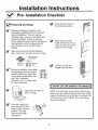
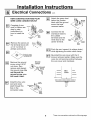
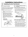
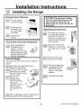
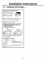
Self Cleaning Free-Standing
Electric Range
Installation
Instructions
EER2000, EER3000 JBP24, JBP26, JBP30, JBP35, JBP48, JBP64, JBP65,
JBP66, JBP67, JBP70, JBP78, JBP79, JBP85, JB940, JB960, JB965
"If you have questions, Call 800-GE-CARES
orvisit
our website
at:
www.G EAppliances.com"
Skill Level:
High !
Completion
Time:
_
Low
1 to 3 Hours
Proper installation is the responsibility of the installer. Product failure due to improper installation
is not covered under the GE Appliance Warranty. See the Owners Manual for warranty
information.
CAUTION:
• NOTE TO INSTALLER- Be sure to leave
these instructions with the consumer.
Before you begin
Read these instructions carefully and
completely.
• IMPORTANT- Save these instructions for
local inspector's
use.
• IMPORTANT- Observe all governing codes
and ordinances.
Parts Included
• OWNER- Keep these instructions
refe re nce.
• WARNING- This appliance
properly grounded.
Anchor
Sleeves
(For Concrete Floors Only)
( UL Approved 40 AMP)
4- Wire Cord
Bracket
must be
Materials Needed
Lag Bolts
Anti-Tip
for future
and leg leveler
4'long
OR 3 -Wire Cord
4'long
Tools You Will Need
J
Pencil
Adjustable
wrench
1/4"Nut
driver
Level
J
Drill with
1/8" Bit
Phillips
Screwdriver
5/16" Hex Head
Nut driver
Pub. No. 31-10463
229c4053P447-3
1
Safety
Glasses
__F
Tape Measure
at-Bladed
Screwdriver
Installation Instructions
IMPORTANT SAFETY INSTRUCTIONS
For Your Safety
WARNING: To reduce the risk of
tipping, the appliance must be
secured by properly installed anti-tip
bracket packed with the appliance.
_
remove
ARNING:
house
For fuse
personal
or open
safety
circuit
breaker before beginning
installation. Failure to do so could result in
serious injury or even death.
All rough-in and spacing dimensions must be met
for safe use of your range. Electricity to the range
can be disconnected at the outlet without moving
the range if the outlet is in the preferred location
(remove lower drawer).
All ranges can tip
Injury to persons could result
Install anti-tip bracket
packed with range
• See Installation Instructions
To reduce the risk of burns or fire when reaching
over hot surface elements, cabinet storage space
above the cooktop should be avoided. If cabinet
storage space is to be provided above the
cooktop, the risk can be reduced by installing a
range hood that sticks out at least 5" beyond the
front of the cabinets. Cabinets installed above a
cooktop must be no deeper than 13".
If you pull the range out and away from the wall
for any reason, make sure the Anti-Tip bracket
is engaged when the range is pushed back
against the wall.
Be sure your appliance is properly installed and
grounded by a qualified technician.
Make sure the cabinets and watt coverings around
the range can withstand the temperatures (up to
200°R) generated by the range.
2
Installation Instructions
Pre-Installation
_'
Preparing
Checklist
I_
the Range
Remove packaging materials. Any
packaging materials must be removed
during installation. This will include
adhesive tape, wire ties, cardboard and
protective plastic. Failure to remove
these materials could result in damage to
the appliance once the appliance has
been turned on and surfaces have
heated.
I_
Close the oven door to
the broil stop position.
Place
sides
close
away
hands on both
of the door. As you
the door, lift up and
from the range.
Open oven door and remove literature
pack, broiler pan and grid, and oven racks.
__ Oven Racks
Broiler Pan
_Literature
and Grid
Lift door up until the
hinges clear the slots.
Pack
Remove Installation Instructions
from literature pack and read it
carefully before you begin. Be
sure to place all literature, Use
and Care, Installation
Instruction, etc. in a safe place
for future reference.
L
Hinge
Clears
Slot
IIoo.oT T.E
oooR
BY
T.E
_r
_z
_,_,.,
___._ ___,
Open the oven door as
,
far as it will go.
Push the hinge
locks
frame, to the unlocked
position.
down
toward
This the
maydoor
require a flat blade
screwdriver.
U__
II1
NOTE: The oven door is very heavy. Be sure you
have a firm grip before lifting the oven door off the
hinges. Use caution once the door is removed. Do
not lay the door on its handle. This could cause
dents or scratches.
u_i:cg:ed
"_°_t _!_
/
"
_sition
Hinge
_,m
3
Installation Instructions
Installation
See Ilustrations
dimensions.
below
Required Clearances
for all rough-in
and spacing
The range may be placed with 0" clearance
the back wall and side walls of the cabinet.
MINIMUM
COOKTOP,
COOKTOP.
DIMENSIONS
WALLS,
1
(flush) at
t
BETWEEN
AND ABOVE
J
J ....................................................................................
*'15" MIN
THE
Make sure the wall covering, countertop
and cabinets around the range can withstand the heat (up to 200°R) generated by
the range.
Allow 30" Minimum clearance between
*0'_
surface units and bottom of unprotected
wood or metal cabinet, and 15" Minimum
between countertop and adjacent cabinet
bottom.
Recommended
surfaces.
spacing
to heat sensitive
Acceptable electrical
outlet area.
Orient the electrical
receptacle so the
length is parallel to the floor.
NOTE: Use a 4 foot power cord to prevent interference
with the storage drawer. Power cords 4.5 or 6 foot long
may have to be dressed to allow for proper drawer closing.
4
Installation Instructions
Electrical Connections
Electrical Requirements
I-_
Making the Electrical
Connection
Remove the wire cover (on the back of the
range) by removing 5 screws using a 1/4" nut
driver. Do not discard these screws.
This appliance must be supplied with the proper
voltage and frequency, and connected to an
individual properly grounded branch circuit;
protected by a circuit breaker or fuse having
amperage as specified on the rating plate. The
rating plate is located above the storage drawer
on the oven frame.
5 Screws to
remove
wire cover
We recommend you have the electrical wiring
and hookup of your range connected by a
qualified electrician. After installation, have the
electrician show you where your main range
disconnect is located.
Check with your local utilities for electrical codes
which apply in your area. Failure to wire your
oven according to governing codes could result in
a hazardous condition. If there are no local
codes, your range must be wired and fused to
meet the requirements d the National Electrical
Code, ANSI/NFPA No. 70-Latest Edition. You can
get a copy by writing:
National Fire Protection Association
cover, make sure that wires do not
become pinched between wire cover
II and
Whenmainback.
reinstalling the one-piece wire
All new constructions,
mobile
homes and installations where
local codes do not allow
grounding through neutral.
Battery March Park
Quincy, MA 02269
Effective January 1, 1996, the National Electrical
Code requires that new, but not existing,
construction utilize a 4 conductor connection to
an electric range. When installing an electric
range in new construction, follow the instructions
in the section on NEW CONSTRUCTION AND
FOUR CONDUCTOR BRANCH CIRCUIT
CONNECTION.
These will require a four-wire flexible cord kit. If
the range is rated between 8,750 and 16,500
watts, the cord kit must be rated for 40 amps125/250 volts. If the range is rated between
16,501 and 22,500 watts, the cord kit must be
rated for 50 amps-125/250
volts. For existing
construction, a three wire flexible cord kit may
be used, and the same ratings apply as described above.
• When using a cord kit rated 40 Amps, remove
the knockout in the connection plate. You
must use a clamp or strain relief to hold the
cord.
• Terminations must be either closed loop
terminals or open end spade lugs.
• On some models, a filter capacitor may be
connected between the black and white leads
on the junction block.
You must use a three-wire, single-phase A.C.
208Y/120 Volt or 240/120 Volt, 60 hertz electrical
system. If you connect to aluminum wiring,
properly installed connectors approved for use
with aluminum wiring must be used.
5
continued
on following
page
Installation
Instructions
Electrical Connections
NEW CONSTRUCTION
AND FOUR
WIRE CORD CONNECTION
KIT
Complete 4 wire
cord kit. Below are
step by step
instructions on
how to install the
kit.
_-_
3Screws|
Connect the red
and black leads to
the outside
terminals and the
white lead to the
center terminal.
Location
Relief
Clamp
Remove the screws on
the terminal block with
a 1/4" nut driver or
phillips screwdriver.
Install the four-wire
cord and strain
relief through the
hole in the
connection plate.
Attach the green lead
below the junction
block with the ground
screw that was
removed earlier.
_r
Ground
ew
Gound
Screw and
_
Connection
Plate
Remove the ground
screw using a 5/16"
nut driver, then
remove and discard
the ground strap. Do
not discard the
ground screw, you
will need it later.
cont.
Black
White
(Green)
Red or
Black
Ground
re\,_
_:_Sc
CGroun
[_1
Push the cord upward (to relieve strain),
while tightening the strain relief clamp.
r_
Re-installremoved
the wireearlier.
cover with
5 the
screws
Make the
sure
wires do not become pinched between
the wire cover and mainback.
d
Wi re
Cover
i
j-4 wire
cord kit
Connection
Plate
Strain
Relief
Clamp
6
Three-wire connection continued on following page
Installation
Instructions
Electrical Connections
THREE-WIRE
CORD CONNECTION
Connect the outer wires to the outside
terminals and the center wire to the
center terminal. Do not remove the
ground strap
KIT
Grounded
Complete
3
3
_>_._
Screws
_]_
wire cord kit.
l
_
oo°t.
Neutral
Terminal
Grounded
Neutral
/_White)
(White)
by step
instructions on
how to install
the kit.
sSt rraPw
Connection
Outer
Wire
Relief
Plate
,.....
Clamp
Wire
I-_
Remove the screws on
the terminal block with a
1/4" nut driver or phillips
screwdriver.
F_a--i
Push the cord upward (to relieve strain),
while tightening the strain relief clamp.
i-_a--i screws
Re-installremoved
the wireearlier.
cover with
5 the
Make the
sure
wires do not become pinched between
the wire cover and mainback.
Knockout in center
of connection plate
may be taken out
Install the three-wire
cord and strain
relief through the
hole in the
connection plate,
Outer
Wi re
!
I
3 wire
_r_
Connection
_.
cord
kit
i
,_._
Wire
Cover
Pla_
-_
] Strain
Relief
Clamp
Special note: If local codes require an
undgrounded neutral, you must do the
following:
a. Remove ground strap.
b. Fasten the white wire to the center terminal.
c. Use grounding terminal or lead to ground unit
in accordance with local codes.
7
Installation
Instructions
Installing the Anti-Tip Bracket
El
Locating The Bracket
[_
The anti-tip bracket, provided with your literature
and broiler pan, must be properly installed to
prevent the range from tipping. Please refer to
the instructions provided with your anti-tip
bracket.
a. Decide whether the bracket will be
installed on the right or left side of range
location.
b. If the bracket side of the range has an
adjacent cabinet, place the bracket
against the back wall and cabinet as
shown in Fig. 1. If there is a countertop
overhang, offset the bracket by the
amount of overhang. If there is no
adjacent cabinet, place the bracket to the
outside edge of the range side panel and
back wall.
nstalling
or
ConcreteThe Bracket in Wood
INSTALLATION-WOOD
CONSTRUCTION
a. Locate the centers of the four holes identified
in Fig. 1 as Floor-Wood and Wall.
b. Drill a 1/8" pilot hole through the pre-marked
areas. Note the angle of the wall screw in
Fig. 2.
c. Mount the Anti-Tip bracket with the four
screws provided.
Attachment To Wall
Bracket
_t_ ii i
Wall
_
Plate
IIIIIIIIIIIIIIIII!111!111111111_,111111111!11,
/111
Screw Must
EnterWood
Fig. 2
Or Metal
Adjacent Cabinet
Or Final Location
Of Range Side Panel
Wall
Side
Rear
Leveling
Leg
Floor-Concrete
Fig. 1
INSTALLATION-CONCRETE
CONSTRUCTION
a. For concrete installation you will need two
1/4"x 1-1/2" lag screws, and two sleeve
anchors.
b. Locate the center of the four holes identified
in Fig. 1 as Floor-Concrete
and Wall. Drill
the recommended
size holes in each.
c. Install the sleeve anchors into the predrilled
concrete holes and install the lag and wall
screws through the Anti-Tip bracket. Make
sure the screws are securely tightened.
Installation Instructions
Installing the Range
Storage Drawer Removal
I-_
Pull the drawer
out until it stops
r-_
Lift
the
the
the
_
CAUTION: The oven door is heavy.
You may need help lifting the door
high enough to slide it into the
hinges slots. Do not lift the door by
the handle.
the front of
drawer until
stops clear
guide.
Remove
drawer.
the
Replacing
r-_
Stop
Final Check of the Anti-Tip Bracket
When installation is
complete and the
range is in place,
inspect to be sure the
rear leveling leg is fully
inserted into the slot of
the Anti-Tip Bracket.
r_
the Oven Door
Pick the Oven Door up
by placing both hands on
each side. The door is
heavy so you may need
help. Do not lift the door
by the handle.
Place
of the
hinge the
arm notch
into the
bottom edge of the hinge
slot.
\ :ii_
:
r
Bottom
Edge
Hinge
Hinge
I-_-1-1 Open
door
as far the
as itoven
will open.
Level the Range
Arm
Notch
Hinge in
Locked Position
The range must be level for proper cooking and
baking.
I-_
I-_
Install the oven racks.(See Owner's
Manual for instructions.)
SPIRIT
Put
a spirit level
or a glass
_R_T I--_====='_
measuring
cup partially
filled with water on one of
the oven racks.
Remove the
storage drawer.
The front leveling
legs can be
LE_ES
"_ _OE
accessed from the
bottom and the
rear legs from the
top.
Push the hinge locks
up against the front
frame of the oven
cavity, to the locked
position.
Hinge Securely
Fitted into Bottom
of Hinge
Slot
Close the oven door.
LOWER
I-_
Use an adjustable wrench to adjust all four
leg levelers until the range is level.
9
Continued on following page
Installation Instructions
Installing the Range cont.
Replacing
the Storage Drawer
rail on the guides.
Push the drawer
in until the
it stops.
Place
drawer
__.
Lift the front of the drawer and push in
until the stops clear the guides.
Lower
front
of the drawer and
push inthe
until
it closes.
SPECIAL INSTRUCTIONS IF YOU HAVE
PROBLEMS WHILE REPLACING THE
STORAGE DRAWER
IF DRAWER WON'T CLOSE
Drawer
Does
Not CIose
Completely
Power Cord
Obstructing
___ln
Drawer
Panel
I l_
May Be
Rear
Drawer
Drawer
Support
_lJ
This Area
Remove and replace,
cord is not obstructing
rail is in the guide.
IF DRAWER
making sure the power
the drawer and/or the
IS CROOKED
Rear Drawer Support is
On Top of Guide Rail
_
Front
Tipped Away From
Body Side
lOn the High Side
Drawer Front Panel
Tipped to One Side
F
Remove and replace
the guide.
!
J
making sure the rail is in
10
Installation Instructions
Final Check List
[]
Check to make sure the circuit breaker
is closed
[]
Be sure power is in service to the building.
[]
Check to be sure that all packing materials
control knobs have been removed.
(Reset) or the circuit fuses are replaced.
and tape on metal panel (if applicable)
under
Operation Check List
[]
Check to make sure the Clock display is energized. If a series of horizontal red lines appear
in the display, disconnect power immediately. Recheck the range wiring connections.
If
change is made to connections, retest again. If no change is required, have building wiring
checked for proper connections and voltage. It is recommended
that the clock be changed if
the red lines appear.
[]
Push in and turn any one of the four surface knobs to "MED" setting to observe that the
element glows within 60 seconds. Turn the knob off when glow is detected. If the glow is not
detected within the time limit, recheck the range wiring connections. If change is required,
retest again. If no change is required, have building wiring checked for proper connections
and voltage.
11
NOTES
Pub. No. 31-10463
12
229c4053P447-3