1
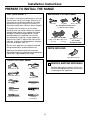
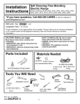
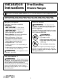
Installation
Instructions
Free-Standing
Electric Ranges
Questions? Call 800.GE.CARES (800.432.2737) or Visit our Website at: www.GEAppliances.com
EER3000, EER3001, JBP24, JBP25, JBP26, JBP35, JBP48, JBP64, JBP66, JBP67, JBP68, JBP69,
JBP71, JBP78, JBP80, JBP82, JBP83, JBP84, JBP99, JB600, JB710, JB905, JB968, JB988, JBS55
BEFORE YOU BEGIN
ANTI-TIP DEVICE
Read these instructions completely
and carefully.
•
IMPORTANT
•
IMPORTANT
•
•
•
•
•
•
WARNING
— To reduce the risk
of tipping, the appliance must be secured by
properly installed Anti-Tip bracket packed
with this appliance.
If the Anti-Tip device supplied with the range
does not fit this application, use the universal
Anti-Tip device WB2X7909.
— Save these
instructions for local inspector’s use.
— Observe all
governing codes and ordinances.
Note to Installer – Be sure to leave these
instructions with the Consumer.
Note to Consumer – Keep these
instructions for future reference.
Skill level – Installation of this appliance
requires basic mechanical skills.
Completion time – 1 to 3 hours
Proper installation is the responsibility of
the installer.
Product failure due to improper installation
is not covered under the Warranty.
WARNING —
• All ranges can tip
• Injury to persons could result
• Install Anti-Tip bracket packed
with range
• See Installation Instructions
If you pull the range out and away from the
wall for any reason, make sure the Anti-Tip
bracket is engaged when the range is pushed
back against the wall.
WARNING
— This appliance must
be properly grounded.
FOR YOUR SAFETY:
WARNING
— Before beginning the
installation, switch power off at service panel
and lock the service disconnecting means to
prevent power from being switched on
accidentally. When the service disconnecting
means cannot be locked, securely fasten a
prominent warning device, such as a tag, to
the service panel.
229C4053P545-5
31-10556-5
06-04 JR
1
Installation Instructions
PREPARE TO INSTALL THE RANGE
FOR YOUR SAFETY:
MATERIALS YOU MAY NEED
All rough-in and spacing dimensions must be
met for safe use of your range. Electricity to
the range can be disconnected at the outlet
without moving the range if the outlet is in
the preferred location (remove lower drawer).
Tin Snips
Lag Bolts
Anchor Sleeves
(For Anti-Tip Bracket Mounted
on Concrete Floors Only)
To reduce the risk of burns or fire when
reaching over hot surface elements, cabinet
storage space above the cooktop should be
avoided. If cabinet storage space is to be
provided above the cooktop, the risk can
be reduced by installing a range hood that
sticks out at least 5” beyond the front of the
cabinets. Cabinets installed above a cooktop
must be no deeper than 13”
.
(UL Approved 40 AMP)
4-Wire Cord OR 3-Wire Cord
4‘ Long
4‘ Long
Be sure your appliance is properly installed
and grounded by a qualified technician.
Squeeze Connector
(For Conduit
Installations Only)
PARTS INCLUDED
Make sure the cabinets and wall coverings
around the range can withstand the temperatures
(up to 200°F.) generated by the range.
Anti-Tip Bracket Kit
TOOLS YOU WILL NEED
1 REMOVE SHIPPING MATERIALS
Drill with 1/8” Bit
Remove packaging materials. Failure to
remove packaging materials could result
in damage to the appliance.
Safety Glasses
Adjustable Wrench
Tape Measure
Pliers
Pencil
1/4” Nut Driver
Level
Phillips Screwdriver
Flat-blade
Screwdriver
2
Installation Instructions
2 PREPARE THE OPENING
See illustrations for all rough-in and spacing
dimensions.
The range may be placed with 0” clearance
(flush) at the back wall and side walls of
the cabinet.
Acceptable electrical
outlet area.
Orient the electrical
receptacle so the length
is parallel to the floor.
**30” Min.
***6”
Min.
**15” Min.
21⁄2”
25”
21⁄2”
*0”
MINIMUM DIMENSIONS BETWEEN COOKTOP,
WALLS AND ABOVE THE COOKTOP:
71⁄2”
36”
*0”
*** Make sure the wall covering, countertop
and cabinets around the range can
withstand the heat (up to 200°F)
generated by the range.
30”
*** Allow 30” minimum clearance between
surface units and bottom of unprotected
wood or metal cabinet, and 15” minimum
between countertop and adjacent cabinet
bottom.
NOTE: Use a 4′ power cord to prevent
interference with the storage drawer.
Power cords 41⁄2 to 6′ long may have to be
dressed to allow for proper drawer closing.
*** Recommended spacing to heat-sensitive
surfaces.
3
Installation Instructions
ELECTRICAL CONNECTIONS
ELECTRICAL REQUIREMENTS
Use only a 3-conductor or a 4-conductor
UL-listed range cord. These cords may be
provided with ring terminals on wire and
a strain relief device.
CAUTION:
For personal safety,
do not use an extension cord with this
appliance. Remove house fuse or open circuit
breaker before beginning installation.
A range cord rated at 40 amps with 125/250
minimum volt range is required. A 50 amp
range cord is not recommended but if used,
it should be marked for use with nominal
13⁄8″ diameter connection openings. Care
should be taken to center the cable and
strain relief within the knockout hole to keep
the edge from damaging the cable.
This appliance must be supplied with the
proper voltage and frequency, and connected
to an individual properly grounded branch
circuit, protected by a circuit breaker or fuse
having amperage as specified on the rating
plate. The rating plate is located above the
storage drawer on the oven frame.
• Because range terminals are not accessible
after range is in position, flexible service
conduit or cord must be used.
We recommend you have the electrical wiring
and hookup of your range connected by a
qualified electrician. After installation, have
the electrician show you where your main
range disconnect is located.
NOTE: If conduit is being used, go to Step 3D
and then to Step 6 or 7.
• On some models, a filter capacitor may be
connected between the black and white
leads on the junction block.
Check with your local utilities for electrical
codes which apply in your area. Failure to
wire your oven according to governing codes
could result in a hazardous condition. If there
are no local codes, your range must be wired
and fused to meet the requirements of the
National Electrical Code, ANSI/NFPA No. 70–
Latest Edition. You can get a copy by writing:
ALL NEW CONSTRUCTIONS,
MOBILE HOMES AND
INSTALLATIONS WHERE
LOCAL CODES DO NOT
ALLOW GROUNDING
THROUGH NEUTRAL,
REQUIRE A 4-CONDUCTOR
UL-LISTED RANGE CORD.
National Fire Protection Association
Batterymarch Park
Quincy, MA 02269
Effective January 1, 1996, the National
Electrical Code requires that new construction
(not existing) utilize a 4-conductor connection
to an electric range.
When installing an electric range in new
construction, follow Steps 3 and 5 for 4-wire
connection.
You must use a 3-wire, single-phase A.C.
208Y/120 Volt or 240/120 Volt, 60 hertz
electrical system.
If the electrical service provided does not
meet the above specifications, have a
licensed electrician install an approved outlet.
4
Installation Instructions
3 POWER CORD AND
STRAIN RELIEF INSTALLATION
A
C
Remove the wire cover (on the back of
the range) by removing five (5) screws
using a 1/4” nut driver.
Do not discard these screws.
5 screws
to remove
wire cover
For power cord installations only (see
the next step if using conduit), assemble
the strain relief in the hole. Insert the
power cord through the strain relief and
tighten. Allow enough slack to easily
attach the cord terminals to the terminal
block. If tabs are present at the end of
the winged strain relief, they can be
removed for better fit.
NOTE: Do not install the power cord
without a strain relief. The strain relief
bracket should be installed before
reinstalling the rear range wiring cover.
Terminal
block
Retaining
tabs
Strain relief
Back of range
Wire cover
B
Power cord
Remove the knockout ring (13⁄8″) located
on bracket directly below the terminal
block. To remove the knockout, use a
pair of pliers to bend the knockout ring
away from the bracket and twist until
ring is removed.
Bracket
Skip to Step 4 or 5.
D
Terminal block
(appearance
may vary)
For conduit installations only, purchase a
squeeze connector matching the diameter
of your conduit and assemble it in the hole.
Insert the conduit through the squeeze
connector and tighten. Allow enough slack to
easily attach the wires to the terminal block.
NOTE: Do not install the conduit without a
squeeze connector. The squeeze connector
should be installed before reinstalling the
rear range wiring cover.
Terminal
block
Knockout ring
in bracket
Knockout
ring removed
Squeeze
connector
Conduit
5
Skip to Step 6 or 7.
Bracket
Installation Instructions
ELECTRICAL CONNECTIONS
4 3-WIRE POWER CORD
INSTALLATION
(CONT.)
5 4-WIRE POWER CORD
INSTALLATION
WARNING:
WARNING:
The neutral or ground
wire of the power cord must be connected
to the neutral terminal located in the
center of the terminal block. The power
leads must be connected to the lower left
and the lower right terminals of the
terminal block.
A
The neutral wire of
the supply circuit must be connected to the
neutral terminal located in the lower center
of the terminal block. The power leads must
be connected to the lower left and the lower
right terminals of the terminal block. The 4th
grounding lead must be connected to the
frame of the range with the ground plate
and the ground screw.
Remove the 3 lower terminal screws
from the terminal block. Insert the 3
terminal screws through each power cord
terminal ring and into the lower terminals
of the terminal block. Be certain that the
center wire (white/neutral) is connected
to the center lower position of the
terminal block. Tighten screws securely
into the terminal block.
DO NOT remove the ground strap
connection.
A
B
C
D
Terminal
block
(appearance
may vary)
Neutral
terminal
Remove the 3 lower terminal screws from
the terminal block. Remove the ground
screw and ground plate and retain them.
Cut and discard the ground strap. DO NOT
DISCARD ANY SCREWS.
Insert the one ground screw into the power
cord ground wire terminal ring, through the
ground plate and into the frame of the range.
Insert the 3 terminal screws (removed earlier)
through each power cord terminal ring and
into the lower terminals of the terminal block.
Be certain that the center wire (white/neutral)
is connected to the center lower position of
the terminal block. Tighten screws securely
into the terminal block.
Ground strap
Before
Ground
plate
Terminal
block
Ground
strap
Ground strap
or
Neutral
terminal
After
Neutral terminal
Terminal
block
Power cord
B
Skip to Step 8 and proceed with the
installation.
Ground
plate
(grounding
to range)
Ground
screw
E
6
Skip to Step 8 and proceed with the installation.
Installation Instructions
6 3-WIRE CONDUIT INSTALLATION
A
7 4-WIRE CONDUIT INSTALLATION
Loosen the 3 lower terminal screws from
the terminal block. Insert the center bare
wire (white/neutral) tip through the bottom
center terminal block opening. On certain
models, the wire will need to be inserted
through the ground strap opening and then
into the bottom center block opening. Insert
the two side bare wire tips into the lower
left and the lower right terminal block
openings. Tighten the screws until the wire
is firmly secured (35 to 50 inch-lbs.). Do not
over-tighten the screws since it could
damage the wires.
A
B
NOTE: ALUMINUM WIRING:
Aluminum building wire may be used
but it must be rated for the correct
amperage and voltage to make
connection. Connect wires according
to this Step 6 or Step 7 depending on
number of wires.
Loosen the three lower terminal screws
from the terminal block. Remove the ground
screw and ground plate and retain them.
Cut and discard the ground strap. DO NOT
DISCARD ANY SCREWS.
Insert the ground bare wire tip between the
range frame and the ground plate (removed
earlier) and secure it in place with the ground
screw (removed earlier). Insert the bare wire
(white/neutral) tip through the bottom center
of the terminal block opening. Insert the two
side bare wire tips into the lower left and the
lower right terminal block openings. Tighten
the screws until the wire is firmly secured
(35 to 50 inch-lbs.). Do not over-tighten the
screws since it could damage the wires.
Before
Ground strap
Terminal
block
Ground strap
Terminal
block
or
Neutral
terminal
After
Wire tips
Terminal
block
Wire tips
Bracket
Conduit
Ground
screw
Wire used, location and enclosure
of splices, etc., must conform to good
wiring practices and local codes.
B
Ground
plate
(grounding
to range)
Bracket
Skip to Step 8 and proceed with the
installation.
Wire used, location and enclosure
of splices, etc., must conform to good
wiring practices and local codes.
C
7
Proceed to Step 8.
Installation Instructions
INSTALL THE RANGE
8 REPLACE THE WIRE COVER
10 REMOVE STORAGE DRAWER
Replace the wire cover on the range back
by sliding its left edge under the retaining
tabs and replacing the five screws removed
earlier. Make sure that no wires are pinched
between the cover and the range back.
A
Pull the drawer out until it stops.
B
Lift the front of the drawer until the
stops clear the guide.
5 screws to
replace wire cover
Stop
Retaining
tabs
C
Back of
range
Wire
cover
9 ANTI-TIP DEVICE INSTALLATION
An Anti-Tip bracket is supplied with
instructions for installation in a variety of
locations. The instructions include all
necessary information to complete the
installation. Read the Safety Instructions
and the instructions that fit your situation
before beginning installation.
Bracket
Wall plate
Screw must
enter wood
or metal
Typical installation of anti-tip bracket attachment to wall
WARNING:
• Range must be secured by Anti-Tip bracket
supplied.
• If the Anti-Tip device supplied with the
range does not fit this application, use the
universal Anti-Tip device WB2X7909.
• See instructions to install (supplied with bracket).
• Unless properly installed, the range could
be tipped by stepping or sitting on the door.
Injury may result from spilled hot liquids
or from the range itself.
8
Remove the drawer.
Installation Instructions
11 LEVEL THE RANGE
A
B
C
13 FINAL INSTALLATION
CHECKLIST
Install the oven shelves in the oven and
position the range where it will be installed.
Check for levelness by
placing a spirit level or
Spirit level
a cup, partially filled
with water, on one of
the oven shelves. If
using a spirit level, take
two readings—with the
level placed diagonally first in one
direction and then the other.
The front leveling legs can be adjusted
from the bottom and the rear legs can be
adjusted from the top or the bottom.
• Check to make sure the circuit breaker is
closed (RESET) or the circuit fuses are
replaced.
• Be sure power is in service to the building.
• Check to be sure that all packing materials
and tape have been removed. This will
include tape on metal panel under control
knobs (if applicable), adhesive tape, wire
ties, cardboard and protective plastic.
Failure to remove these materials could
result in damage to the appliance once the
appliance has been turned on and surfaces
have heated.
• Check to make sure that the door and
drawer are parallel to each other and that
both operate smoothly. If they do not, see
the Owner’s Manual for proper replacement.
Lower
range
Leg
leveler
• Check to make sure that the rear leveling
leg is fully inserted into the Anti-Tip bracket
and that the bracket is securely installed.
Raise
range
D
Use an open-end or adjustable wrench
to adjust the leveling legs until the range
is level.
14 OPERATION CHECKLIST
• Turn on one of the surface units to observe
that the element glows within 60 seconds.
Turn the unit off when glow is detected. If
the glow is not detected within the time
limit, recheck the range wiring connections.
If change is required, retest again. If no
change is required, have building wiring
checked for proper connections and voltage.
12 REPLACE THE
STORAGE DRAWER
A
Place the drawer rail on the guides.
B
Push the drawer in until it stops.
C
Lift the front of the drawer and push in
until the stops clear the guides.
• Check to make sure the Clock (on models
so equipped) display is energized. If a series
of horizontal red lines appear in the display,
disconnect power immediately. Recheck the
range wiring connections. If change is
made to connections, retest again. If no
change is required, have building wiring
checked for proper connections and
voltage. It is recommended that the clock
be changed if the red lines appear.
D
Lower the front of the drawer and push
in until it closes.
• Be sure all range controls are in the OFF
position before leaving the range.
Stop
9
Notes
10
Notes
11
12
Printed in the United States