1
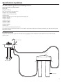
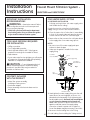
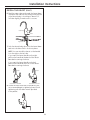
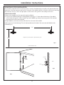
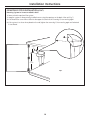
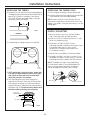
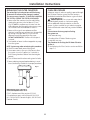
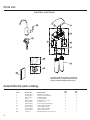
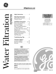
Water Filtration System
GEAppliances.com
Safety Instructions . . . . . . . . . . . . .2
Owner’s Manual and
Installation Instructions
System Overview . . . . . . . . . . . . .3–5
GNSV70RBL
GNSV75RWW
Installation Instructions . . . .6–12
Battery Installation . . . . . . . . . . . . . . . .11
Faucet Installation . . . . . . . . . . . . . . . .7, 8
Feed Water Supply . . . . . . . . . . . . . . .6, 7
Filter Replacement . . . . . . . . . . . . . . . . .12
Flush Procedure . . . . . . . . . . . . . . . . . . .12
Installing the Tubing . . . . . . . . . . . . . . .11
System Installation . . . . . . . . . . . . . .9, 10
Troubleshooting Tips . . . . . . . . . .13
Consumer Support
Consumer Support . . . . . . . .Back Cover
Parts List/Catalog . . . . . . . . . . . . . . . . . .14
Warranty . . . . . . . . . . . . . . . . . . . . . . . . . .15
GNSV70RBL and GNSV75RWW are Tested and Certified
by NSF International against NSF/ANSI Standard 42 for
the reduction of Chlorine: Taste and Odor and Particulate
Class I and Standard 53 for the reduction of Lead, Cyst,
Turbidity, Asbestos, Mercury, Lindane, Atrazine, Benzene
and VOC.
215C1219P001
49-50234-3
02-09 JR
IMPORTANT SAFETY INFORMATION.
WARNING: Read entire manual. Failure to follow all guides and rules could cause personal injury or property
damage.
■ Check with your local public works department for plumbing codes. You must follow their guidelines as you install the Water Filtration
system.
SAFETY PRECAUTIONS
■ Use the Water Filtration system on a potable, safe-to-drink, home COLD water supply only. The filter canisters will not purify the water,
or make it safe to drink.
■ Do not use on a hot water supply (100°F max.). Install on a cold water line only.
WARNING:
Do not use with water that is microbiologically unsafe or of unknown quality without adequate
disinfection before or after the system. Systems certified for cyst reduction may be used on disinfected water that may contain
filterable cysts.
PROPER INSTALLATION
This Water Filtration system must be properly installed and located in accordance with the Installation Instructions before it is used.
CAUTION:
To reduce the risk of property damage due to water leakage, install or store where it will not be exposed to
temperatures below freezing or exposed to any type of weather. Water freezing in the system may damage it and may result in water
leakage, damaging property. Change the filter out if it was exposed to freezing temperatures. Do not attempt to treat water over 100°F.
WARNING: Discard all unused and packaging material after installation. Small parts remaining after installation could
be a choke hazard.
■ Your Water Filtration system will withstand up to 120 pounds per square inch (psi) water pressure. If your house water supply pressure
is higher than 80 psi, install a pressure reducing valve before installing the Water Filtration system.
READ AND FOLLOW THIS SAFETY INFORMATION CAREFULLY.
SAVE THESE INSTRUCTIONS
2
Specifications Guidelines.
The Water Filtration System Uses the Following Canisters
Models GNSV70RBL and GNSV75RWW
FQSVF Filter
(160 gallon capacity)
Filter—White canisters with green band
• Reduces dirt, rust and sediment
• Reduces Chlorine: Taste and Odor
• Reduces Lead
• Reduces filterable Cysts (such as cryptosporidium and giardia)
• Reduces Turbidity
• Reduces Asbestos
• Reduces Mercury
• Reduces Lindane
• Reduces Atrazine
• Reduces Benzene
• Reduces VOC
• 0.5–1 micron nominal particulate reduction
This system conforms to NSF/ANSI 42 and 53 for the specific performance claims as verified and sustained by test data. See Performance
Data Sheet for details.
Installation Overview
Locate the drinking water system on the cold water supply pipe, under the kitchen and/or bathroom sink, to filter the cold
drinking water.
Filtered Water Faucet
Sink
Manifold
Hot
Cold
Water Supply Valve
Inlet
Outlet
Filter Canisters
3
Performance Data Sheet.
SmartWater Filtration System GNSV70RBL and GNSV75RWW
Using Filter FQSVF
■ This System has been tested according to NSF/ANSI 42 and 53 for the reduction of the substances listed below. The concentration of the indicated
substances in water entering the system was reduced to a concentration less than or equal to the permissible limit for water leaving the system,
as specified in NSF/ANSI 42 and 53.
■ Actual performance may vary with local water conditions.
WARNING:
Do not use with water that is microbiologically unsafe or with water of unknown quality without adequate disinfection
before or after the system. Systems certified for cyst reduction may be used on disinfected waters that may contain filterable cysts.
Minimum
Maximum Permissible
Min.
Required
Product
Water
Concentration
Reduction
97.50%
—
98.10%
97.50%
—
97.30%
>50%
—
>85%
0.1 NTU
1 #/L
<0.17 MF/L
<0.001 mg/L
98.80%
>99.99%
>99.00%
>99.30%
98.20%
>99.99%
>99.00%
>99.30%
0.5 NTU
99.95%
99%
0.010 mg/L
<0.001 mg/L
<0.001 mg/L
>99.30%
>99.30%
0.010 mg/L
0.0065 mg/L
<0.0002 mg/L
<0.0002 mg/L
96.60%
>96.70%
0.002 mg/L
0.006 mg/L ± 10%
0.0059 mg/L
<0.0002 mg/L
<0.0002 mg/L
96.60%
96.70%
0.002 mg/L
0.002 mg/L ± 10%
0.015 mg/L ± 10%
0.009 mg/L ± 10%
0.00193 mg/L
0.014 mg/L
0.00873 mg/L
<0.00002 mg/L
<0.0005 mg/L
<0.0005 mg/L
0.00005 mg/L
<0.0005 mg/L
<0.0005 mg/L
>98.80%
>96.40%
>94.10%
98.80%
>96.40%
>94.10%
0.0002 mg/L
0.005 mg/L
0.003 mg/L
0.00620 mg/L
97.90%
98.20%
95%
—
—
—
2.0 mg/L + 10%
—
≥ 10000 particles
0.5 NTU***
99.95% red.
99% red.
0.010 mg/L
11 + 1 NTU***
Min. 50000L
—
0.15 mg/L + 10%
11.0 NTU
140000 #/L
280 MF/L
0.150 mg/L
0.1 NTU
1 #/L
<0.17 MF/L
<0.001 mg/L
0.010 mg/L
0.15 mg/L + 10%
0.140 mg/L
0.002 mg/L
0.006 mg/L ± 10%
0.002 mg/L
0.0002 mg/L
0.001 mg/L
0.003 mg/L
Chlorine
T &O
Particulate**
% Reduction
Average
Influent
Challenge Concentration
Parameter
Turbidity
Cysts
Asbestos
Lead,
pH 6.5
Lead,
pH 8.5
Mercury,
pH 6.5
Mercury,
pH 8.5
Lindane
Benzene
Atrazine
Standard No. 42: Aesthetic Effects
Effluent
USEPA
MCL
Influent
Average
Average
Maximum
2.00 mg/L
<0.05 mg/L
<0.05 mg/L
—
—
—
4100000 #/mL
76500 #/mL
110000 #/mL
Standard No. 53: Health Effects
VOC Reduction
Chloroform
0.080 mg/L
0.300 ± 10%
0.340 mg/L
0.00098 mg/L
*Tested using a flow rate of 0.60 gpm (2.27 l/min); pressure of 60 psig; pH of 7.5 ± 0.5; temp. of 68° ± 5°F (20° ± 3°C)
**Measurement in particles/mL. Particles used were 0.5–1 microns.
***NTU—Nephelometric Turbidity Units
Operating Specifications
Capacity: certified for up to 160 gallons (605 l); up to six months
Pressure requirement: 35–120 psi (2.8–8.2 bar)
Temperature: 33–100°F (0.6–38°C)
Flow rate: 0.60 gpm (2.27 l/min)
Replacement Filter Canisters/Estimated Replacement Costs
FQSVF—Replacement filter canister $35–40
For replacement parts, call toll-free 800.626.2002 (U.S.), 800.663.6060 (Canada–English), 800.361.3869 (Canada–French)
State of California
Department of Health Services
Water Treatment Device
Certificate Number
04 - 1601
IOWA RESIDENTS ONLY:
Date Issued: February 9, 2009
Trademark/Model Designation
GXSV65 F
GQSV65 F
GNSV70 FBL
GNSV75 FWW
GXSV65 R
GNSV75 RWW
GNSV70 RBL
Replacement Element(s)
FQSVF
FQSVF
FQSVF
FQSVF
FQSVF
FQSVF
FQSVF
Manufacturer: General Electric Company
Store or Seller’s Name
Address
The water treatment device(s) listed on this certificate have met the testing requirements pursuant to Section
116830 of the Health and Safety Code for the following health related contaminants:
Microbiological Contaminants and Turbidity
Cysts
Turbidity
Organic Contaminants
Atrazine
Lindane
Benzene
VOCs
Alachlor
Atrazine
Benzene
Carbofuran
Carbon Tetrachloride
Chlorobenzene
Chloropicrin
2,4-D
DBCP
o-Dichlorobenzene
p-Dichlorobenzene
1,2-Dichloroethane
1,1-Dichloroethylene
cis-1,2-Dichloroethylene
trans-1,2-Dichloroethylene
1,2-Dichloropropane
cis-1,3-Dichloropropylene
Dinoseb
Rated Service Capacity: 160 gal
Inorganic/Radiological Contaminants
City
Asbestos
Lead
Mercury
Endrin
Ethylbenzene
EDB
Haloacetonitriles (HAN)
Bromochloroacetonitrile
Dibromoacetonitrile
Dichloroacetonitrile
Trichloroacetonitrile
Haloketones (HK)
1,1-Dichloro-2-Propanone
1,1,1-Trichloro-2-Propanone
Heptachlor
Heptachlor Epoxide
Hexachlorobutadiene
Hexachlorocyclopentadiene
Lindane
Methoxychlor
Pentachlorophenol
Simazine
Styrene
1,1,2,2-Tetrachloroethane
Tetrachloroethylene
Toluene
2,4,5-TP (Silvex)
Tribromoacetic Acid
1,2,4-Trichlorobenzene
1,1,1-Trichloroethane
1,1,2-Trichloroethane
Trichloroethylene
Trihalomethanes (THMs)
Bromodichloromethane
Bromoform
Chloroform
Chlorodibromomethane
Xylenes
Rated Service Flow: 0.6 gpm
Do not use where water is microbiologically unsafe or with water of unknown quality, except that
systems certified for cyst reduction may be used on disinfected waters that may contain filterable cysts.
4
State
Zip
Seller’s signature
Customer’s signature
Date
Telephone
Performance Data Sheet.
Organic Chemicals Reduced by Chloroform Surrogate Testing
Contaminant
Alachlor
Atrazine
Benzene
Carbofuran
Carbon Tetrachloride
Chlorobenzene
Chloropicrin
2,4-D
Dibromochloropropane (DBCP)
o-Dichlorobenzene
p-Dichlorobenzene
1,2-Dichloroethane
1,1-Dichloroethylene
cis-1,2-Dichloroethylene
trans-1,2-Dichloroethylene
1,2-Dichloropropane
cis-1,3-Dichloropropylene
Dinoseb
Endrin
Ethylbenzene
Ethylene Dibromide (EDB)
Haloacetonitriles (HAN):
Bromochloroacetonitrile
Dibromoacetonitrile
Dichloroacetonitrile
Trichloroacetonitrile
Avg.1
Influent (μg/L)2
50
100
81
190
78
77
15
110
52
80
40
88
83
170
86
80
79
170
53
88
44
Max.
Effluent (μg/L)2
1.03
3.03
1.03
1.03
1.84
1.03
0.24
1.74
0.023
1.03
1.03
4.85
1.03
0.53
1.03
1.03
1.03
0.24
0.594
1.03
0.023
22
24
9.6
15
0.54
0.64
0.24
0.34
Influent challenge levels are average influent concentrations determined in surrogate qualification testing.
μg/L means Micrograms Per Liter.
Maximum product water level was not observed but was set at the detection limit of the analysis.
4 Maximum product level is set at a value determined in surrogate qualification testing.
5 Chemical reduction percent and maximum product water level calculated at chloroform 95% breakthrough point as determined in surrogate qualification testing.
6 The surrogate test results for heptachlor Epoxide demonstrated a 98% reduction. These data were used to calculate an upper occurrence concentration, which would produce a maximum product
water level at the MCL.
1
2
3
Testing was performed under standard laboratory conditions; actual performance may vary.
NOTE: Substances reduced are not necessarily in your water. Filter must be maintained according to manufacturer’s instructions, including replacement of filter cartridges.
WARNING:
Do not use with water that is microbiologically unsafe or of unknown quality without adequate disinfection before or after the system. Systems certified for cyst
reduction may be used on disinfected waters that contain filterable cysts.
5
Installation
Instructions
Faucet Mount Filtration System –
GNSV70RBL and GNSV75RWW
COLD WATER SUPPLY FITTING
IMPORTANT INSTALLATION
RECOMMENDATIONS
A. PREFERRED INSTALLATION
(Utilizing existing kitchen sink water supply valve
and flexible faucet tubing)
A typical connection using the included water
supply fitting is shown in the illustration below.
1. Close the water shut-off valve that is immediately
in front of the supply tube and open the faucets
to drain water from the sink cold water pipe.
2. Remove the nut that connects the cold water faucet
to the supply tube. Some water may spill out.
WARNING
— Read entire manual. Failure
to follow all guides and rules could cause personal
injury or property damage.
• Check with your local public works department
for plumbing codes. You must follow their guides
as you install the Water Filtration system.
TOOLS AND MATERIALS REQUIRED
FOR INSTALLATION
NOTES:
• Be sure to turn off the water supply and open
a faucet to drain the pipe.
• Make sure the gasket is installed in the water
supply fitting.
• Phillips screwdriver
• Two (2) adjustable wrenches
• Electric drill and drill bit to drill 1″ hole (type as
required) if mounting hole is needed for faucet
• Tape measure
• If your main water line is a rigid pipe, you will require
a compression fitting and possibly other plumbing
hardware to complete the installation.
Cold Water
Faucet Stud
Gasket
Water Supply Fitting
1/4″ Tubing to
Water Filter Inlet
CAUTION
— To avoid damaging the sink,
consult a qualified plumber or installer for drilling
procedures. Special drill bits may be needed for
porcelain or stainless steel.
Fig. 1
Cold
Water Pipe
CONTENTS INCLUDED
WITH THE PRODUCT
• Water filter system assembly,
including mounting screws
• Feed water adapter
• Faucet assembly with electronic base monitor
and tubing
Cold Water Shutoff
3. Hand-tighten the water supply fitting onto the cold
water faucet. Be sure the gasket, as shown, is in
place before final assembly. Finish tightening with
an adjustable wrench. Be careful not to overtighten
or cross-thread, as damage to the threads can
occur. Make sure the 1/4″ quick connection is not
against a wall that causes the supply tubing
connection to bend. A quarter turn to tighten or
loosen the adapter may be necessary to avoid this.
4. Reconnect faucet tubing line to the fitting.
5. Install tubing. (See Installing the Tubing section.)
6
Installation Instructions
COLD WATER SUPPLY FITTING (CONT.)
INSTALL THE FAUCET
B. OPTIONAL HOME INSTALLATION
(Where codes permit)
Saddle Valve: Saddle valve must be able to
connect with 1/4-inch tubing supplied with the
system. Not supplied with product; check your
local hardware or home service store for
product. Saddle valve typically requires 1/2″
OD tubing or larger.
NOTE: Codes in the state of Massachusetts
require installation by a licensed plumber and
do not permit the use of the saddle valve. For
installation, use plumbing code 248-CMR of the
Commonwealth of Massachusetts.
1. Turn off the cold water supply and install saddle
valve as required by product selection. (Be sure to
follow manufacturer’s installation instructions.)
Be sure there is room underneath and above
the sink to make the needed connections. Before
starting, make sure there is sufficient room for the
faucet base and unit. Select one of the following
places to install the faucet:
A. In an existing sink spray attachment or soap
dispenser hole.
B. In a hole to be drilled in the sink top.
C. In a hole to be drilled in the countertop, next
to the sink.
NOTES:
• Be sure the faucet base will fit flat against the
surface at the selected location so the bottom
gasket between the base and surface area
will seal.
• Make sure to leave enough clearance at the back
of the faucet in case you need to remove it.
DANGER
— If hole is required to be drilled
in pipe, to protect yourself from serious injury or
fatal shock, use a battery-powered hand drill only
to make the hole. DO NOT USE AN ELECTRIC DRILL.
2. Open saddle valve after complete system has
been installed.
Installation Steps (refer to illustration below
for clarification)
1. If drilling is needed, make a 1″ diameter hole.
Be sure to use the proper procedure for drilling
porcelain or stainless steel. Special drill bits
may be needed. Consult a qualified plumber
for the proper procedure.
C. OPTIONAL INSTALLATION
(For installation with rigid pipe between supply
valve and sink faucet)
Option 1
1. Remove pipe from supply valve and sink faucet.
2. Obtain flexible pipe sized to your plumbing.
3. Install flexible pipe.
4. Go back to A. Preferred Installation section
step 3.
CAUTION:
When drilling in Stainless
Steel, the edges may be sharp and could puncture
the tube. Be careful to not cut yourself or damage
the tube.
2. Remove the faucet body and base by turning
the base counterclockwise.
Option 2
1. Obtain compression fittings to fit rigid pipe.
2. Obtain any other fittings required to connect
compression fittings to feed water adapter.
3. Remove pipe from supply valve.
4. Cut pipe to fit length of assembled fittings and
adapter.
3. Remove the butterfly bracket from the screw.
Then insert the screw into the top of the base
and reattach the butterfly bracket.
4. Align the gasket to cover the hole completely.
Then place the butterfly bracket on the base
into the hole.
Screw
5. Install compression fitting to pipe.
Base
6. Go back to A. Preferred Installation section
step 3.
Sink
Gasket
Butterfly Bracket
NOTE: Above described materials are not
included with the product.
5. Tighten the screw to secure the butterfly bracket
to the underside of the sink top. The base should
be firmly in place and should not wobble or turn.
7
Installation Instructions
INSTALL THE FAUCET (CONT.)
6. Feed the water tube up through the faucet base.
Then push the tube into the fitting on the bottom
of the faucet body. It should go in about 3/4″.
Pull tube slightly to make sure it is secure.
Faucet Body
Gasket
Base
Sink
Toggle Screw
7. Push the faucet body down into the faucet base
and twist clockwise until it clicks into place.
NOTE: You can install the faucet so the handle
is on the right or the left side.
If you want the faucet handle on the right,
position the handle at the back of the faucet
base before turning clockwise.
If you want the faucet handle on the left,
position the handle at the front of the faucet
base before turning clockwise.
Faucet
Faucet handle on the RIGHT
Faucet
Faucet handle on the LEFT
8. Locate the hole at the rear of the base. Insert
set screw and begin to tighten by hand. Finish
tightening with the allen wrench provided
in the packet.
8
Installation Instructions
MOUNTING SYSTEM INSTALLATION
Pick a location under the sink to mount the system. Location should be easily accessible, with clearance between
the bottom of the filter canisters and the floor or bottom of the cabinet; any less will result in difficulty of removing
filter canisters (see Fig. 5). Allow enough space on either side of the system for the tubing connections.
SCREW INSTALLATION
1. Remove this template from the manual for easier installation.
2. The top of the template openings should be placed a minimum of 17 inches above the bottom of the cabinet
or floor where the system is to be mounted (Fig. 4 and 5). NOTE: Any distance lower may result in filter canisters
interfering with the floor when removed.
3. Tape template to wall, then mark the wall where the screws are to be installed.
Install screws into the wall, leaving 3/16 inch clearance between the head of the screw and wall (drill pilot holes
if needed) (Fig. 6).
5 inches
Template for screw hole pattern on back of filtration system
17 inches
Fig. 4
Bottom of Cabinet or Floor
5 inches
3/16 inch
Screws
Wall
17 inches
Screw
Fig. 6
Fig. 5
9
Installation Instructions
MOUNTING SYSTEM INSTALLATION (CONT.)
Mounting System to Screws Installed in Wall
1. Remove shrink wrap from filter system.
2. Hang the system on the previously installed screws using the openings on the back of the unit (Fig. 7).
3. If the head of the screw will not slide into the upper slot, back out the screw by 1/4 turn and try again.
4. If the system is too loose when placed on the wall, tighten the screws by 1/4 turn and try again until a desired
fit is achieved.
5 inches
Min.
17 inches
Fig. 7
10
Installation Instructions
INSTALLING THE TUBING
INSTALLING THE TUBING (CONT.)
1. Measure 3/4″ from the end of each remaining piece
of tubing (faucet end and inlet end) and mark with a
pencil (Fig. 8). (Check for roundness, smoothness,
cuts, nicks, flat spots and sharp edges. It may be
necessary to recut the tubing.)
5. Pull out slightly on tubing to ensure a good seal.
6. Install the other end of the tubing from the inlet side
of the manifold to the feed water adapter.
NOTE: Inspect the ends of the tubing to be sure
there are no imperfections and that the end of the
tubing is cut square. It may be necessary to cut the
tubing again.
3/4″
(19 mm)
Fig. 8
INSTALL THE BATTERY
INCORRECT
1. Remove the lens cover from the faucet base.
Grip it from both sides and pull forward.
2. Install one CR2032 3V battery with the “+” side
down into the battery tray.
2. Locate fittings for tubing on bottom of manifold.
3. The amber LED light will flash 5 times,
indicating a proper installation and system reset.
If the amber light does not flash, check
the position of the battery and make sure
it is installed correctly.
4. Slide the lens cover back into the faucet base.
5. Normally, the light is off. After 6 months of use,
the amber LED light will flash every 30 seconds,
indicating the time to replace the filter canister.
OUTLET
INLET
Inlet from
supply valve
NOTE: The amber LED light may stop blinking
if it is allowed to blink for an extended period of
time. To ensure proper operation, the battery
should be replaced with every filter change.
Outlet
to faucet
3. NOTE: Water flow is from left to right. Water inlet
is on the left side and water outlet is on the right
side. Failure to follow will result in water leaks
when filter canisters are removed.
4. Push the tubing firmly into each fitting on the
manifold until the line is flush with the fitting collar.
(If the tubing is removed, re-cut the end, measure,
mark and re-insert). Tubing must be fully inserted to
avoid leaks (Fig. 9). (To remove tubing, depress and
hold white collet; pull tubing out to remove.)
Faucet Base
White Collet
(DO NOT REMOVE)
Insertion line
3 "
4
Insert tubing
Engagement
3/4″ (3/8″ tubing)
Fig. 9
11
Lens Cover
Battery “+” Side Down
Installation Instructions
REPLACING THE FILTER CANISTERS
FLUSH PROCEDURE
The amber light in the faucet base will flash every
30 seconds to indicate a filter change is needed.
This occurs every 6 months. TO PROPERLY MAINTAIN
THE SYSTEM, CHANGE THE FILTER AS REQUIRED.
1. Remove the filter canisters from the manifold by
rotating the canisters to the left about 1/3 turn
(Fig. 11). NOTE: A small amount of water from the
tubing between the filter and the faucet may come
out. A small towel should be able to catch it.
2. Remove foil on top of new replacement filter
canisters. Install the new canisters into the manifold
by turning to the right about 1/3 turn until the
alignment marks line up and the filter stops.
DO NOT OVERTIGHTEN. The filter will rise up as it
is turned.
3. Turn handle on faucet to allow trapped air to purge
from the system.
NOTE: System may make noise during this procedure.
4. Check for water leaks around the system.
5. Once water starts to flow out of the faucet, allow
the system to run for 3 gallons (or 5 minutes) to
flush out any harmless carbon fines that may be
present.
6. Turn off faucet and check around system for leaks.
7. Remove battery tray and replace battery to reset
timer. (See Battery Installation for proper procedure.)
Whenever water of unknown quality is passed through
the GE Water Filtration system, the filter canisters
should be discarded and the filtration system flushed.
WARNING:
Do not use with water that is
microbiologically unsafe or of unknown quality
without adequate disinfection before or after the
system. Systems certified for cyst reduction may be
used on disinfected water that may contain filterable
cysts.
Circumstances that may require flushing
the system are:
• Boil water advisory
• Flooding of the GE Water Filtration system
• Long-term non-use
The procedure for flushing the GE Water Filtration
system is:
1. See Replacing the Filter Canisters section and follow
steps 1–5.
Fig. 11
To install
To remove
Replacement Filter Canisters/
Estimated Replacement Costs
FQSVF—Replacement filter canister $35–$40
For replacement parts, call toll-free 800.626.2002
(U.S.), 800.663.6060 (Canada–English), 800.361.3869
(Canada–French).
12
Before you call for service…
Troubleshooting Tips
Save time and money! Review the chart
below first and you may not need to call
for service.
Problem
Possible Causes
What To Do
Water contains tiny
black particles
New filter canisters contain
activated carbon.
• Turn on the filtered water faucet and allow these initial carbon
particles to purge from the canisters. Turn off the faucet when the
water is clear.
Water has air bubbles
and is cloudy
Air in system after installation.
• Will go away after water runs for a while.
Indicator light on the
faucet base is flashing
Six months usage has occurred.
This is the maximum life of
the filter canisters.
• Replace both filter canisters and battery in the faucet base.
Indicator light on the
Normal operation.
faucet base is not blinking
Battery may need to be replaced.
Indicator light on the
faucet base is not
working when new
battery is installed
Battery may need to be
replaced or it may have been
installed incorrectly.
• Does not blink until 6 months of operation has passed.
• Normally the light is not on. The light blinks every 30 seconds to
indicate a filter change is needed. This occurs about every 6 months.
• Replace battery. Indicator light will blink rapidly 5 times to indicate
proper installation and operation.
• Observe orientation markings on the holder. Install with battery
“+” side down.
Chlorine taste and/or
The filter canisters are no
odor in the product water longer reducing chlorine,
taste and odor from the
water supply.
• Replace the filter canisters.
Water dispenses
very slowly
The filters have been installed
for too long.
• A six-month change-out period is recommended. Replace both
filter canisters.
The filter canisters have
become clogged.
• High sediment levels can cause premature clogging. Replace both
filter canisters.
Fittings are leaking
Tubing may not be installed
properly.
• Fully follow the installation instructions and be sure the tubing is
free of nicks, burrs, etc., and is installed to the proper depth.
No water dispensing
from system
Filter canisters not fully
installed.
• Fully follow the filter replacement instructions.
13
Parts List.
GNSV70RBL, GNSV75RWW
To obtain replacement parts, call toll-free
800.626.2002 (U.S.), 800.663.6060 (CanadaEnglish), 800.361.3869 (Canada-French)
General Electric parts catalog.
ITEM
1
2
3
4
5
11
12
13
13
14
14
999
14
GE CAT. NO.
WS19X10016
WS19X10015
WS22X10045
FQSVF
WS03X10046
WS07X10020
WS60X10016
WS15X10068
WS15X10069
WS10X10039
WS10X10040
49-50234
DESCRIPTION
MANIFOLD ASSEMBLY
COVER, DUAL MANIFOLD
ELBOW & COLLET
FILTER SET (VOC)
O-RING KIT (2 LG, 4 SM)
TUBING—6′0″
INLET ADAPTER—NO VALVE
FAUCET BODY, CHROME
FAUCET BODY, WHITE
FAUCET BASE, CHROME
FAUCET BASE, WHITE
OWNER’S MANUAL & INST. INSTR.
GNSV70RBL
(00)
QTY
1
1
2
1
1
1
1
1
–
1
–
1
GNSV75RWW
(00)
QTY
1
1
2
1
1
1
1
–
1
–
1
1
GE Water Filtration System Warranty.
All warranty service provided by our SmartWater™ Authorized Servicer
Network. To schedule service, on-line, visit us at GEAppliances.com, or call
800.952.5039 in the U.S., or toll-free 866.777.7627 in Canada. Please have
serial number and model number available when calling for service.
Staple your receipt here.
Proof of the original purchase date
is needed to obtain service under
the warranty.
For The Period Of: GE Will Replace:
One Year
From the date of the
original purchase
Any part of the Water Filtration System (excluding filters) which fails due to a defect in materials
or workmanship. During this limited one-year warranty, GE will also provide, free of charge, all labor
and related service to replace the defective part.
What GE Will Not Cover:
■ Service trips to your home to teach you how to use
the product.
■ Filter cartridges and batteries after 30 days from date
of purchase.
■ Improper installation, delivery or maintenance.
■ Damage to the product caused by accident, fire, floods
or acts of God.
■ Failure of the product if it is abused, misused, or used for
other than the intended purpose or used commercially.
■ Use of this product where water is microbiologically unsafe or
of unknown quality, without adequate disinfection before or
after the system. Systems certified for cyst reduction may be
used on disinfected water that may contain filterable cysts.
■ Incidental or consequential damage caused by possible defects
with this appliance.
EXCLUSION OF IMPLIED WARRANTIES—Your sole and exclusive remedy is product repair as provided in this Limited
Warranty. Any implied warranties, including the implied warranties of merchantability or fitness for a particular
purpose, are limited to one year or the shortest period allowed by law.
This warranty is extended to the original purchaser and any succeeding owner for products purchased for home use within the
USA. If the product is located in an area where service by a GE Authorized Servicer is not available, you may be responsible for a
trip charge or you may be required to bring the product to an Authorized GE Service location for service. In Alaska, the warranty
excludes the cost of shipping or service calls to your home.
Some states do not allow the exclusion or limitation of incidental or consequential damages. This warranty gives you
specific legal rights, and you may also have other rights which vary from state to state. To know what your legal rights
are, consult your local or state consumer affairs office or your state’s Attorney General.
Warrantor: General Electric Company. Louisville, KY 40225
15
Consumer Support.
GE Appliances Website
GEAppliances.com
Have a question or need assistance with your appliance? Try the GE Appliances Website 24 hours a day, any day of the year!
For greater convenience and faster service, you can now download Owner’s Manuals, order parts or even schedule service on-line.
Schedule Service
GEAppliances.com
Expert GE repair service is only one step away from your door. Get on-line and schedule your service at your convenience any day
of the year! Or call 800.GE.CARES (800.432.2737) during normal business hours.
Real Life Design Studio
GEAppliances.com
GE supports the Universal Design concept—products, services and environments that can be used by people of all ages, sizes
and capabilities. We recognize the need to design for a wide range of physical and mental abilities and impairments. For details
of GE’s Universal Design applications, including kitchen design ideas for people with disabilities, check out our Website today.
For the hearing impaired, please call 800.TDD.GEAC (800.833.4322).
Extended Warranties
GEAppliances.com
Purchase a GE extended warranty and learn about special discounts that are available while your warranty is still in effect. You can
purchase it on-line anytime, or call 800.626.2224 during normal business hours. GE Consumer Home Services will still be there after
your warranty expires.
Parts and Accessories
GEAppliances.com
Individuals qualified to service their own appliances can have parts or accessories sent directly to their homes (VISA, MasterCard and
Discover cards are accepted). Order on-line today, 24 hours every day or by phone at 800.626.2002 during normal business hours.
Instructions contained in this manual cover procedures to be performed by any user. Other servicing generally should be referred
to qualified service personnel. Caution must be exercised, since improper servicing may cause unsafe operation.
Contact Us
GEAppliances.com
If you are not satisfied with the service you receive from GE, contact us on our Website with all the details including your phone number,
or write to:
General Manager, Customer Relations
GE Appliances, Appliance Park
Louisville, KY 40225
Register Your Appliance
GEAppliances.com
Register your new appliance on-line—at your convenience! Timely product registration will allow for enhanced communication and
prompt service under the terms of your warranty, should the need arise. You may also mail in the preprinted registration card included
in the packing material.