1
GE Consumer & Industrial
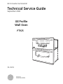
Technical Service Guide
September 2008
GE Profile
Wall Oven
PT925
31-9176
GE Appliances
General Electric Company
Louisville, Kentucky 40225
IMPORTANT SAFETY NOTICE
The information in this service guide is intended for use by
individuals possessing adequate backgrounds of electrical,
electronic, and mechanical experience. Any attempt to repair a
major appliance may result in personal injury and property
damage. The manufacturer or seller cannot be responsible for the
interpretation of this information, nor can it assume any liability in
connection with its use.
WARNING
To avoid personal injury, disconnect power before servicing
this product . If electrical power is required for diagnosis or test
purposes, disconnect the power immediately after performing the
necessary checks.
RECONNECT ALL GROUNDING DEVICES
If grounding wires, screws, straps, clips, nuts, or washers used to
complete a path to ground are removed for service, they must be
returned to their original position and properly fastened.
GE Consumer & Industrial
Technical Service Guide
Copyright © 2008
All rights reserved. This service guide may not be reproduced in whole or in part
in any form without written permission from the General Electric Company.
–2–
Table of Contents
Bake Element ...................................................................................................................................................................... 36
Broil Element ....................................................................................................................................................................... 35
Component Locator Views ........................................................................................................................................... 25
Control Features ................................................................................................................................................................ 6
Control Voltage .................................................................................................................................................................. 48
Convection Bake Element ............................................................................................................................................. 37
Convection Fan Blade ..................................................................................................................................................... 36
Convection Fan Motor .................................................................................................................................................... 37
Convection Fan Troubleshooting .............................................................................................................................. 53
Cooling Fan .......................................................................................................................................................................... 41
Diagnostics and Service Information ...................................................................................................................... 48
Door Assemblies................................................................................................................................................................ 28
Door Hinge Receivers ..................................................................................................................................................... 42
Electronic Oven Control ................................................................................................................................................. 32
Electronic Oven Control ................................................................................................................................................. 45
Error Codes .......................................................................................................................................................................... 57
General Troubleshooting............................................................................................................................................... 54
Introduction ......................................................................................................................................................................... 4
Lock Assembly ................................................................................................................................................................... 38
Lock Out Relay ................................................................................................................................................................... 40
Meat Probe and Outlet ................................................................................................................................................... 42
Nomenclature .................................................................................................................................................................... 5
Oven Component Access Chart ................................................................................................................................ 27
Oven Components ........................................................................................................................................................... 28
Oven Light Assembly ...................................................................................................................................................... 42
Oven Light Bulbs ............................................................................................................................................................... 43
Oven Removal .................................................................................................................................................................... 32
Oven Sensor Ohmmeter Test ...................................................................................................................................... 53
Oven Temperature Sensor............................................................................................................................................ 35
Rear Access Panels .......................................................................................................................................................... 34
Relay Boards ....................................................................................................................................................................... 38
Ribbon Cable Assembly ................................................................................................................................................. 41
Sail Switch Assembly ...................................................................................................................................................... 40
Schematics and Wiring Diagrams ............................................................................................................................ 58
Service Mode ...................................................................................................................................................................... 50
Side Access Panels ........................................................................................................................................................... 33
Smoke Eliminators............................................................................................................................................................ 44
Thermal Cut Outs .............................................................................................................................................................. 39
Top Access Panels ............................................................................................................................................................ 34
Using the Ribbon Cable for Troubleshooting ....................................................................................................... 51
Warranty .............................................................................................................................................................................. 62
–3–
Introduction
The new 30-in. wall ovens have superior style and performance. These ovens feature electronic controls that
utilize the precision of modern digital technology. Additional features include:
•
Glass Touch LCD Controls - Combine a smooth, easy-to-clean glass design with large, easy-to-read
graphics to facilitate easier usage
•
Flat Back Convection Fan - Features a more streamlined convection fan that better accommodates
baking and roasting pans
•
Convection Bake - Provides ideal airflow
throughout the oven cavity, ensuring better
baking results
•
Convection Roast - Provides even cooking and
consistent results, roasting meats faster than a
traditional oven
•
Closed Door Broiling - Provides cleaner broiling
with lower wattage heating elements
•
Self Clean Oven - Conveniently cleans the oven
cavity without need of scrubbing
–4–
Nomenclature
Model Number
P T 9 2 5 B R B B
GE Cooking Product
P = Profile
Product Color
SS = Stainless Steel
BB = Black
WW = White
Configuration
T = 30-in. Wall Oven
Model Year Designator
Glass Color
S = Integrated Stainless
B = Integrated Black
W = Integrated White
Feature Pack
Designates features–the higher
the number, the more features.
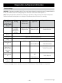
Serial Number
The first two characters of the serial number
identify the month and year of manufacture.
Example:
AR123456S = January, 2008
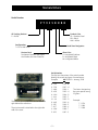
Nomenclature
The nomenclature plate is located on the front
right behind the oven door.
The mini-manual is attached to the right side
wall of the oven.
A - JAN
D - FEB
F - MAR
G - APR
H - MAY
L - JUN
M - JUL
R - AUG
S - SEP
T - OCT
V - NOV
Z - DEC
–5–
2008 - R
2007 - M
2006 - L
2005 - H
2004 - G
2003 - F
2002 - D
2001 - A
2000 - Z
1999 - V
1998 - T
1997 - S
The letter designating
the year repeats every
12 years.
Example:
T - 1974
T - 1986
T - 1998
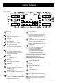
Control Features
Features and appearance
may vary.
BAKE Pad
COOK TIME Pad
Touch to select the bake function.
Touch to select the broil function.
Touch this pad and then touch the number
pads to set the amount of time you want
your food to cook. The oven will shut off
when the cooking time has run out.
PIZZA Pad
Display
BROIL HI/LO Pad
Touch to select the Pizza function.
OVEN LIGHT Pad
Touch to turn the oven light on or off.
SELF CLEAN HI/LO Pad
Touch to select self-cleaning function.
See the Using the self-cleaning upper
and lower ovens section.
WARM/PROOF Pad
Touch to keep cooked foods warm.
See the How to Set the Lower and Upper
Ovens for Warming section.
HELP Pad
Touch to get help on a specific function
or to change options.
TIMER Pad
Touch to select the timer feature.
CLOCK Pad
Touch to set the clock.
START Pad
Must be touched to start any cooking
or cleaning function.
CLEAR/OFF Pad
Touch to cancel ALL oven operations except
the clock and timer.
DELAY START Pad
Use along with COOK TIME or SELF CLEAN
HI/LO pads to set the oven to start and stop
automatically at a time you set.
Shows the time of day, oven temperature,
whether the oven is in the bake, broil
or self-cleaning mode and the times set
for the timer or automatic oven operations.
Number Pads
Use to set any function requiring numbers
such as the time of day on the clock,
the timer, the oven temperature,
the internal food temperature,
the start time and length of operation
for timed baking and self-cleaning.
If your oven was set for a timed oven operation
and a power outage occurred, the clock and all
programmed functions must be reset.
The time of day will flash in the display when
there has been a power outage.
CONVECTION BAKE Pad
Touch to select baking with the convection
function.
CONVECTION ROAST Pad
Touch to select roasting with the convection
function.
SLOW COOK Pad
Touch to select the Slow Cook function.
PROBE Pad
Touch when using the probe to cook food.
NOTE: When setting times, you are setting hours
and minutes only. The lowest time you can set is
one minute.
–6–
(Continued next page)
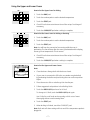
Using the Upper and Lower Ovens
How to Set the Upper Oven for Baking
1. Touch the BAKE pad.
2. Touch the number pads to set the desired temperature.
3. Touch the START pad.
4. Check if food is done at minimum time of the recipe. Cook longer if
necessary.
5. Touch the CLEAR/OFF pad when cooking is complete.
_________________________________________________________________________________________
How to Set the Lower Oven for Baking or Roasting
1. Touch the BAKE pad.
2. Touch the number pads to set the desired temperature.
3. Touch the START pad.
Note: You will hear the convection fan running while the oven is
preheating. The fan will stop after the oven is preheated and the display
shows your set temperature. This is normal.
4. Check if food is done at minimum time of the recipe. Cook longer if
necessary.
5. Touch the CLEAR/OFF pad when cooking is complete.
_________________________________________________________________________________________
How to Set the Upper and Lower Ovens
Note:
•
Close the doors. Always broil with the doors closed.
•
If your oven is connected to 208 volts, rare steaks may be broiled
by preheating the broiler and positioning the oven rack one position
higher.
1. Place the meat or fish on a broiler grid in a broiler pan.
2. Follow suggested rack positions in the Broiling Guide.
3. Touch the BROIL HI/LO pad once for HI Broil.
To change to LO Broil, touch the BROIL HI/LO pad again.
Use LO Broil to cook foods such as poultry or thick cuts of meat
thoroughly without over-browning them.
4. Touch the START pad.
5. When broiling is finished, touch the CLEAR/OFF pad.
Note: Broil and self-clean settings will not work if the temperature probe is
plugged in.
–7–
How to Set an Immediate Start and Automatic Stop
The oven will turn on immediately and cook for a selected length of time.
At the end of the cooking time, the oven will turn off automatically.
1. Touch the BAKE pad.
2. Touch the number pads to set the desired oven temperature.
3. Touch the COOK TIME pad.
Note: If the recipe requires preheating, you may need to add time to the
cooking time.
4. Touch the number pads to set the desired length of cooking time. The
minimum cooking time you can set is 1 minute.
The oven temperature that you set and the cooking time that you
entered will be in the display.
5. Touch the START pad.
Note: An attention tone will sound if you are using timed baking and do
not touch the START pad.
The oven will turn on, and the display will show the cooking time
countdown and the changing temperature starting at 100°F. (The
temperature display will start to change once the oven temperature
reaches 100°F.) When the oven reaches the temperature you set, 3 beeps
will sound.
The oven will continue to cook for the set amount of time, then turn off
automatically, unless the WARM feature was set. See the How to Set the
Lower and Upper Ovens for Warming section.
6. Touch the CLEAR/OFF pad to clear the display, if necessary. Remove
the food from the oven. Remember, even though the oven turns off
automatically, food left in the oven will continue cooking after the
oven turns off.
–8–
(Continued next page)
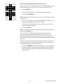
How to Set a Delayed Start and Automatic Stop
The oven will turn on at the time of day you set, cook for a specific length
of time, and then turn off automatically.
Make sure the clock shows the correct time of day.
1. Touch the BAKE pad.
2. Touch the number pads to set the desired oven temperature.
3. Touch the COOK TIME pad.
Note: If the recipe requires preheating, you may need to add time to the
cooking time.
4. Touch the number pads to set the desired length of cooking time. The
minimum cooking time you can set is 1 minute.
The oven temperature that you set and the cooking time that you
entered will be in the display.
5. Touch the DELAY START pad.
6. Touch the number pads to set the time of day you want the oven to
turn on and start cooking.
7. Touch the START pad.
Note:
•
An attention tone will sound if you are using timed baking and do not
touch the START pad.
•
If you would like to check the times you have set, touch the DELAY
START pad to check the start time you have set or touch the COOK
TIME pad to check the length of cooking time you have set.
When the oven turns on at the time of day you set, the display will show
the cooking time countdown and the changing temperature starting
at 100°F. (The temperature display will start to change once the oven
temperature reaches 100°F.) When the oven reaches the temperature you
set, 3 beeps will sound.
The oven will continue to cook for the set amount of time, then turn off
automatically, unless the WARM feature was set. See the How to Set the
Lower and Upper Ovens for Warming section.
8. Touch the CLEAR/OFF pad to clear the display, if necessary. Remove
the food from the oven. Remember, even though the oven turns off
automatically, food left in the oven will continue cooking after the
oven turns off.
–9–
Using the Probe on the Lower Convection Oven
How to Set the Lower Oven for Baking/Roasting When Using the Probe
1. Insert the probe fully into the food.
2. Plug the probe into the outlet in the oven. Make sure it’s pushed all the
way in. Close the oven door. Make sure the probe cable is not touching
the broil element.
3. Touch the PROBE pad. Display will show “Set Probe Temperature.”
4. Touch the number pads to set the desired internal food or meat
temperature. The maximum internal temperature for the food that
you can set is 200ºF.
5. Touch the BAKE pad.
6. Touch the number pads to set the desired oven temperature.
7. Touch the START pad.
After the internal temperature of the food reaches 100°F, the changing
internal temperature will be shown in the display.
8. When the internal temperature of the food reaches the number
you have set, the probe and the oven turn off, and the oven control
signals. To stop the signal, touch the CLEAR/OFF pad. Use hot pads to
remove the probe from the food. Do not use tongs to pull on the probe
― they might damage it.
Note: If the probe is removed from the oven while the probe is still
cooking, the oven will not automatically turn off.
To change the oven temperature during the Bake/Roast cycle, touch the
BAKE pad and then the number pads to set the new temperature.
Note: You can use the Kitchen Timer even though you cannot use timed
oven operations while using the probe.
– 10 –
Using the Clock, Kitchen Timer, and Control Lock
To Set the Clock
The clock must be set to the correct time of day for the automatic oven
timing functions to work properly. The time of day cannot be changed
during a timed baking or self-cleaning cycle.
1. Touch the CLOCK pad.
2. Touch the number pads.
3. Touch the START pad.
_________________________________________________________________________________________
To Set the Kitchen Timer
1. Touch the TIMER pad.
2. Touch the number pads until the amount of time you want shows in
the display. For example, to set 2 hours and 45 minutes, touch 2, 4
and 5 in that order. If you make a mistake, touch the TIMER pad and
begin again.
3. Touch the START pad.
After touching the START pad, SET disappears; this tells you the time is
counting down, although the display does not change until one minute
has passed. Seconds will not be shown in the display until the last minute
is counting down.
4. When the Kitchen Timer reaches :00, the control will beep 3 times
followed by one beep every 6 seconds until the TIMER pad is touched.
The 6-second tone can be canceled by following the steps in the Special
features of your oven control section under Tones at the End of a Timed
Cycle.
_________________________________________________________________________________________
To Reset the Kitchen Timer
If the display is still showing the time remaining, you may change it by
touching the TIMER pad, then touch the number pads until the time you
want appears in the display.
If the remaining time is not in the display (clock, delay start or cooking
time are in the display), recall the remaining time by touching the TIMER
pad and then touching the number pads to enter the new time you want.
_________________________________________________________________________________________
To Cancel the Kitchen Timer
Touch the TIMER pad twice.
– 11 –
(Continued next page)
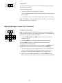
Control Lock
Your control will allow you to lock out the touch pads so they cannot be
activated when touched.
To lock/unlock the controls:
1. Touch and hold the 9 and 0 pads for 3 seconds.
The oven display will show “Oven controls locked” for several seconds,
then “Locked.”
2. To unlock the control, touch and hold the 9 and 0 pads for 3 seconds.
Note: The CONTROL LOCK mode affects all touch pads. No touch pads will
work when this feature is activated.
Adjusting the Upper or Lower Oven Thermostat
To Adjust the Thermostat
+
Note: This adjustment will only affect baking and roasting temperatures;
it will not affect broiling or self-cleaning temperatures. The adjustment will
be retained in memory after a power failure.
1. Touch the BROIL HI/LO and BAKE pads at the same time until the
display shows "SF".
2. Touch the BAKE pad. A two-digit number shows in the display.
Touch the BAKE pad again to alternate between increasing and
decreasing the oven temperature.
To adjust the upper oven thermostat, touch the upper oven BAKE pad. To
adjust the lower oven thermostat, touch the lower oven BAKE pad.
3. The oven temperature can be adjusted up to (+) 35ºF hotter or (-) 35ºF
cooler. Touch the number pads the same way you read them. For
example, to change the oven temperature 15ºF, touch 1 and 5.
4. When you have made the adjustment, touch the START pad to go
back to the time of day display. Use your oven as you would normally.
– 12 –
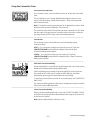
Using the Convection Oven
Convection Fan Operation
In a convection oven, a fan circulates hot air over, under, and around the
food.
This circulating hot air is evenly distributed throughout the oven. As a
result, foods are evenly cooked and browned ― often in less time than
with convection heat.
Note: To maximize cooking evenness, the fan is designed to rotate in both
directions, with a pause in between. This is normal.
The convection fan shuts off when the oven door is opened. DO NOT leave
the door open for long periods of time while using convection cooking or
you may shorten the life of the convection heating element.
_________________________________________________________________________________________
Introduction
The convection oven comes with two convection baking modes:
Multi and 1 Rack:
MULTI ― for convection cooking on more than one rack. Touch the
CONVECTION BAKE pad and then the 2 pad. See the Multi-Rack
Convection Baking section below.
1 RACK ― for convection cooking on one rack only. Touch the
CONVECTION BAKE pad and then the 1 pad. See the 1 Rack Convection
Baking section below.
_________________________________________________________________________________________
Multi-Rack Convection Baking
Because heated air is circulated evenly throughout the oven, foods can be
baked with excellent results using multiple racks.
Multi-rack baking may increase cook times slightly for some foods, but
the overall result is time saved. Cookies, muffins, biscuits, and other
quickbreads give very good results with multi-rack baking.
To cook food on more than one rack in convection bake, use CONVECTION
BAKE MULTI.
For multi-rack baking, place the flat rack in the highest (C) position and the
offset rack in the middle (B) position.
_________________________________________________________________________________________
1 Rack Convection Baking
When convection baking with only 1 rack, use CONVECTION BAKE 1 RACK
and follow the rack positions recommended in the Using the Oven section
of the Owner's Manual.
Note: Ideal for baked foods cooked on 1 rack.
– 13 –
(Continued next page)
How to Set the Lower Oven for Convection Baking or Roasting
OR
1. Touch the CONVECTION BAKE pad and then the 2 pad for multirack convection baking. This mode is used for cooking food items
on more than one rack (i.e., 2, 3, or more racks) at the same time in
convection bake. See the Multi-Rack Convection Baking section for
more information.
Touch the CONVECTION BAKE pad and then the 1 pad for one-rack
convection baking. This mode is used for cooking food items on only
one rack in convection bake.
Touch the CONVECTION ROAST pad for convection roasting.
2. Touch the number pads to set the oven temperature.
3. Touch the START pad.
Note: If the Auto Recipe™ Conversion Feature is on, it will automatically
reduce the set regular baking temperature by 25°F to the appropriate
convection temperature in convection bake mode. See Auto Recipe™
Conversion in the Special Features section.
To change the oven temperature, touch the CONVECTION BAKE or
CONVECTION ROAST pad and then the number pads to set the new
temperature.
When the oven starts to heat, the changing temperature, starting at
100°F, will be displayed. When the oven reaches the temperature you set,
3 beeps will sound.
4. Touch the CLEAR/OFF pad when finished.
Note:
•
You will hear a fan while cooking with convection. The fan will stop
when the door is opened, but the heat will not turn off.
•
You may hear the oven clicking during baking. This is normal.
•
In convection bake modes, for maximum cooking evenness, the fan is
designed to rotate in both directions, with a pause in between. This is
normal.
_________________________________________________________________________________________
How to Set the Lower Oven for Convection Roasting when Using the
Probe
Note: For best results when roasting large turkeys and roasts, we
recommend using the probe included in the convection oven
1. Place the oven rack in the position that centers the food between the
top and bottom of the oven. Insert the probe into the meat. Make sure
it is pushed all the way in.
2. Plug the probe into the outlet in the oven. Make sure it is pushed all the
way in. Close the oven door.
3. Touch the CONVECTION ROAST pad.
4. Touch the number pads to set the desired oven temperature.
5. Touch the PROBE pad.
6. Touch the number pads to set the desired internal meat temperature.
– 14 –
(Continued next page)
Note: The maximum internal temperature that you can set is 200°F.
7. Touch the START pad.
The display will flash "PROBE", and the oven control will signal if the probe
is inserted into the outlet and you have not set a probe temperature and
pressed the START pad.
When the oven starts to heat, the word "LO" will be in the display.
After the internal temperature of the meat reaches 100°F, the changing
internal temperature will be shown in the display.
Note: To change the oven temperature during the Convection Roast cycle,
touch the CONVECTION ROAST pad and then touch the number pads to
set the new desired temperature.
8. When the internal temperature of the meat reaches the number
you have set, the probe and the oven turn off, and the oven control
signals. To stop the signal, touch the CLEAR/OFF pad. Use an oven
mitt to remove the probe from the food. Do not use tongs to pull on
the probe ― they might damage it.
Note: If the probe is removed from the oven while the probe is still
cooking, the oven will not automatically turn off.
Using the Timed Features for Convection Cooking
How to Set an Immediate Start and Automatic Stop
OR
The lower oven will turn on immediately and cook for a selected length of
time. At the end of the cooking time, the oven will turn off automatically.
Make sure the clock shows the correct time of day.
1. Touch the CONVECTION BAKE pad and then the 2 pad for multi-rack
convection baking. This mode is used for cooking food items on more
than one rack (i.e., 2, 3, or more racks) at the same time in convection
bake. See the Multi-Rack Baking section for more information.
Touch the CONVECTION BAKE pad and then the 1 pad for one-rack
convection baking. This mode is used for cooking food items on only
one rack in convection bake.
Touch the CONVECTION ROAST pad for convection roasting.
2. Touch the number pads to set the oven temperature.
3. Touch the COOK TIME pad.
Note: If the recipe requires preheating, you may need to add time to the
cooking time.
4. Touch the number pads to set the desired length of cooking time. The
minimum cooking time you can set is 1 minute. The oven temperature
that you set and the cooking time that you entered will be in the
display.
– 15 –
(Continued next page)
5. Touch the START pad.
The oven will turn on, and the display will show the cooking time
countdown and the changing temperature starting at 100°F. (The
temperature display will start to change once the oven temperature
reaches 100°F.) When the oven reaches the temperature you set, 3 beeps
will sound.
Note: If the Auto Recipe™ Conversion Feature is on, it will automatically
reduce the set regular baking temperature by 25°F to the appropriate
convection temperature in convection bake mode. See Auto Recipe™
Conversion in the Special Features section.
The oven will continue to cook for the set amount of time, then turn off
automatically, unless the WARM feature was set. See the How to Set the
Oven for Warming section.
After the oven turns off, the end-of-cycle tone will sound.
6. Touch the CLEAR/OFF pad to clear the display, if necessary. Remove
the food from the oven. Remember, even though the oven turns off
automatically, food left in the oven will continue cooking after the
oven turns off.
_________________________________________________________________________________________
How to Set a Delayed Start and Automatic Stop
OR
The lower oven will turn on at the time of day you set, cook for a specific
length of time, and then turn off automatically.
Make sure the clock shows the correct time of day.
1. Touch the CONVECTION BAKE pad and then the 2 pad for multi-rack
convection baking. This mode is used for cooking food items on more
than one rack (i.e., 2, 3, or more racks) at the same time in convection
bake. See the Multi-Rack Baking section for more information.
Touch the CONVECTION BAKE pad and then the 1 pad for one-rack
convection baking. This mode is used for cooking food items on only
one rack in convection bake.
Touch the CONVECTION ROAST pad for convection roasting.
2. Touch the number pads to set the oven temperature.
3. Touch the COOK TIME pad.
Note: If the recipe requires preheating, you may need to add time to the
cooking time.
4. Touch the number pads to set the desired length of cooking time. The
minimum cooking time you can set is 1 minute.
The oven temperature that you set and the cooking time that you
entered will be in the display.
5. Touch the DELAY START pad.
6. Touch the number pads to set the time of day you want the oven to
turn on and start cooking.
– 16 –
(Continued next page)
7. Touch the START pad.
Note:
•
An attention tone will sound if you are using timed baking or roasting
and do not touch the START pad.
•
If you would like to check the times you have set, touch the DELAY
START pad to check the start time you have set, or touch the COOK
TIME pad to check the length of cooking time you have set.
When the oven turns on at the time of day you set, the display will show
the cooking time countdown and the changing temperature starting
at 100°F. (The temperature display will start to change once the oven
temperature reaches 100°F.) When the oven reaches the temperature you
set, 3 beeps will sound.
Note: If the Auto Recipe™ Conversion Feature is on, it will automatically
reduce the set regular baking temperature by 25°F to the appropriate
convection temperature in convection bake mode. See Auto Recipe™
Conversion in the Special Features section.
The oven will continue to cook for the programmed amount of time, then
shut off automatically, unless the WARM feature was set. See the How to
Set the Oven for Warming section.
After the oven turns off, the end-of-cycle tone will sound.
8. Touch the CLEAR/OFF pad to clear the display, if necessary. Remove
the food from the oven. Remember, even though the oven shuts off
automatically, food left in the oven will continue cooking after the
oven turns off.
Using the Slow Cook, Pizza, Warming, and Proofing Features
How to Set the Lower Oven For Slow Cook
Slow Cook is designed for long hours of unattended cooking.
1. Touch the SLOW COOK pad once for HI Slow Cook.
To change to LO Slow Cook, touch the SLOW COOK pad again.
2. Touch the number pads to select the desired setting – 1 for Beef, 2 for
Poultry, 3 for Pork, or 4 for Stews. Use the 1–Beef setting if you are
unsure which setting to use.
3. Touch the number pads to set the desired length of cooking time. For
the HI setting, the cooking time must be between 3 and 8 hours. For
the LO setting, the cooking time must be between 3 and 12 hours.
4. Touch the START pad.
When the Slow Cook function has completed, the oven will go into the
Warm mode. The display will say “Cooking Complete Keeping Warm.”
The total time the oven will be on (Slow Cook time plus Warm time) is 12
hours. This is because of the 12-Hour Shutdown feature See the 12-Hour
Shutdown section.
Note: If a power outage occurs while the oven is in Slow Cook, the oven
will shut off.
– 17 –
(Continued next page)
How to Set the Upper Oven For Pizza
Adjust rack position for type of pizza tray being used.
1. Touch the PIZZA pad.
2. Touch the number pads to select 1 for fresh or 2 for frozen pizza.
3. Touch the number pads to set the baking temperature.
4. Touch the START pad.
_________________________________________________________________________________________
How to Set the Lower and Upper Ovens for Warming
OR
The WARM feature keeps cooked foods hot.
This feature is not designed to reheat cold food.
To use the WARM feature, touch the WARM pad or the WARM/PROOF pad
once and then the START pad.
To use the WARM feature after Timed Baking or Roasting, complete the
following steps:
1. Touch the mode of cooking that you want to use (BAKE, CONVECTION
BAKE MULTI, CONVECTION BAKE 1 RACK, or CONVECTION ROAST).
2. Touch the number pads to set the oven temperature.
3. Touch the COOK TIME pad.
4. Touch the number pads to set the desired length of cooking time.
5. Touch the WARM pad or the WARM/PROOF pad once.
6. Touch the START pad.
_________________________________________________________________________________________
How to Set the Lower Oven for Proofing
The proofing feature maintains a warm environment useful for rising
yeast-leavened products.
1. Place the covered dough in the oven on rack B or C.
Note: For best results, cover the dough with a cloth or with greased plastic
wrap (the plastic may need to be anchored underneath the container so
the oven fan will not blow it off).
2. Touch the WARM/PROOF pad twice.
The display will read "PrF" (proof).
The oven interior light turns on and remains on during proofing.
The proofing feature automatically provides the optimum temperature
for the proofing process, and therefore, does not have a temperature
adjustment.
3. Set the TIMER for the minimum proof time.
4. When proofing is finished, touch the CLEAR/OFF pad.
– 18 –
Using the Self-Cleaning Upper and Lower Ovens
How to Set the Upper/Lower Oven for Cleaning
The oven doors must be closed and all controls set correctly for the cycle
to work properly.
1. Touch the SELF CLEAN HI/LO pad once for a 5-hour clean time or
twice for a 3-hour clean time.
A 3-hour self-clean time is recommended for use when cleaning small,
contained spills. A self-clean time of 5 hours is recommended for a
dirtier oven.
2. If a time other than 5 hours or 3 hours is needed, use the number pads
and enter the desired clean time.
You can change the clean time to any time between 3 hours and 5 hours,
depending on how dirty your oven is.
3. Touch the START pad.
The upper and lower oven doors lock automatically. The display will show
the clean time remaining. It will not be possible to open the oven doors
until the temperature drops below the lock temperature and LOCKED goes
off in the control display.
When LOCKED goes off, you will be able to open the doors.
Note:
•
The word LOCKED will flash and the word door will display if you set
the clean cycle and forget to close the oven doors.
•
To stop a clean cycle, touch the CLEAR/OFF pad. When LOCKED goes
off, indicating the ovens have cooled below the locking temperature,
you will be able to open the doors.
You can set a clean cycle in both ovens at the same time; however, they
will not self-clean at the same time. The last oven set will automatically
delay its start until the end of the first oven’s clean cycle.
When either oven is set to self-clean, both oven doors will lock. The ovens
cannot be used when one of the ovens is set to self-clean.
_________________________________________________________________________________________
How to Delay the Start of Cleaning
1. Touch the SELF CLEAN HI/LO pad once for a 5-hour clean time or
twice for a 3-hour clean time.
A 3-hour self-clean time is recommended for use when cleaning small,
contained spills. A self-clean time of 5 hours is recommended for a
dirtier oven.
2. If a time other than 5 hours or 3 hours is needed, use the number pads
and enter the desired clean time.
You can change the clean time to any time between 3 hours and 5 hours,
depending on how dirty your oven is.
3. Touch the DELAY START pad.
– 19 –
(Continued next page)
4. Using the number pads, enter the time of day you want the clean
cycle to start.
5. Touch the START pad.
The upper and lower oven doors lock automatically. The display will show
the start time. It will not be possible to open the oven doors until the
temperature drops below the lock temperature and LOCKED goes off in
the control display.
When LOCKED goes off, you will be able to open the doors.
Special Features of the Oven Control
The special feature modes can only be activated while the display is showing the time of day. They remain in
the control’s memory until the steps are repeated.
To enter a special feature for either oven, you must first touch the upper oven BROIL HI/LO and BAKE pads
at the same time. The lower oven BROIL HI/LO and BAKE pads will not activate special features. When the
display shows your choice, touch the START pad. The special features will remain in memory after a power
failure, except for the Sabbath feature, which will have to be reset.
Help Function
Touch the HELP pad to get additional information on the keypad of your
choice.
Touch the HELP pad and the display will show “Press keypad for help on
that feature or 1 for options.”
The following options can be adjusted using the method described here or
through HELP.
_________________________________________________________________________________________
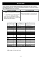
12-Hour Shutdown
+
With this feature, should you forget and leave the oven on, the control will
automatically turn off the oven after 12 hours during baking functions or
after 3 hours during a broil function.
If you wish to turn off this feature, follow the steps below.
1. Touch the upper oven BROIL HI/LO and BAKE pads at the same time
until the display shows "SF".
2. Touch the DELAY START pad until "no shdn" (no shut-off) appears in
the display.
3. Touch the START pad to activate the no shut-off and leave the control
set in this special features mode.
– 20 –
(Continued next page)
Fahrenheit or Celsius Temperature Selection
+
+
Your oven control is set to use the Fahrenheit temperature selections, but
you may change this to use the Celsius selections.
1. Touch the upper oven BROIL HI/LO and BAKE pads at the same time
until the display shows "SF".
2. Touch the COOK TIME and BROIL HI/LO pads at the same time. The
display will show "F" (Fahrenheit).
3. Touch the COOK TIME and BROIL HI/LO pads again at the same time.
The display will show "C" (Celsius).
4. Touch the START pad.
_________________________________________________________________________________________
Tones at the End of a Timed Cycle
+
At the end of a timed cycle, 3 short beeps will sound followed by one
beep every 6 seconds until the CLEAR/OFF pad is touched. This continual
6-second beep may be canceled.
To cancel the 6-second beep:
1. Touch the upper oven BROIL HI/LO and BAKE pads at the same time
until the display shows "SF".
2. Touch the BROIL pad. The display shows "CONTI BEEP" (continuous
beep). Touch the BROIL pad again. The display shows "SINGLE BEEP".
(This cancels the one beep every 6 seconds.)
3. Touch the START pad.
_________________________________________________________________________________________
Tone Volume
+
This feature allows you to adjust the tone volumes to a more acceptable
volume. There are three possible volume levels.
1. Touch the upper oven BROIL HI/LO and BAKE pads at the same time
until the display shows "SF".
2. Touch the COOK TIME pad. The display will show "2 BEEP". This is the
middle volume level.
Touch the COOK TIME pad again. The display will show "3 BEEP". This
is the loudest volume level.
Touch the COOK TIME pad again. The display will show "1 BEEP". This
is the quietest volume level.
For each time the level is changed, a tone will sound to provide an
indication of the volume level.
3. Choose the desired sound level (1 BEEP, 2 BEEP, or 3 BEEP).
4. Touch the START pad to activate the level shown.
– 21 –
(Continued next page)
12-Hour, 24-Hour or Clock Blackout
+
Your control is set to use a 12-hour clock.
If you would prefer to have a 24-hour military time clock or black out the
clock display, follow the steps below.
1. Touch the upper oven BROIL HI/LO and BAKE pads at the same time
until the display shows "SF".
2. Touch the CLOCK pad once. The display will show "12 hr". If this is the
choice you want, touch the START pad.
Touch the CLOCK pad again to change to the 24-hour military time clock.
The display will show "24 hr". If this is the choice you want, touch the
START pad.
Touch the CLOCK pad again to black out the clock display. The display will
show "OFF". If this is the choice you want, touch the START pad.
Note: If the clock is in the black-out mode, you will not be able to use the
Delay Start function.
_________________________________________________________________________________________
Auto Recipe™ Conversion
+
When using convection bake, the Auto Recipe™ Conversion feature will
automatically convert entered regular baking temperatures to convection
baking temperatures.
This feature is activated so that the display will show the actual converted
(reduced) temperature. For example, if you enter a regular recipe
temperature of 350°F and touch the START pad, the display will show
"CON" and the converted temperature of 325°F.
To deactivate the feature:
1. Touch the upper oven BAKE and BROIL HI/LO pads at the same time
until the display shows "SF".
2. Touch the CONVECTION BAKE pad. The display will show "CON ON".
Touch the CONVECTION BAKE pad again. The display will show "CON
OFF".
3. Touch the START pad.
To reactivate the feature, repeat steps 1–3 above, but touch the START
pad when "CON ON" is in the display.
– 22 –
Using the Sabbath Feature (lower oven only)
(Designed for use on the Jewish Sabbath and Holidays)
The Sabbath feature can be used for baking only. It cannot be used for convection, broiling, self-cleaning, or
delay start cooking.
+
How to Set for Regular Baking
Make sure the clock shows the correct time of day and both ovens are off.
1. On the upper oven, touch and hold both the BROIL HI/LO pad and the
BAKE pad, at the same time, until the display shows "SF".
Note: If bake or broil appears in the display, the BROIL HI/LO pad and
the BAKE pad were not touched at the same time. Touch the upper oven
CLEAR/OFF pad and begin again.
2. Tap the DELAY START pad until "SAb bAtH" appears in the display.
3. Touch the START pad twice and "]" will appear in the display.
4. Touch the lower oven BAKE pad. No signal will be given.
5. Using the number pads, enter the desired temperature between 170°F
and 550°F. No signal or temperature will be given.
6. Touch the lower oven START pad.
7. After a random delay period of approximately 30 seconds to 1 minute,
"] [" will appear in the display indicating that the oven is baking. If
"] [" doesn’t appear in the display, start again at Step 4.
Note: When the display shows "]", the oven is set in Sabbath. When the
display shows "] [", the oven is baking.
To adjust the oven temperature, touch the lower oven BAKE pad, enter the
new temperature using the number pads and touch the START pad.
Note: The CLEAR/OFF pad and the COOK TIME pad of the lower oven are
active during the Sabbath feature.
_________________________________________________________________________________________
How to Set for Timed Baking―Immediate Start and Automatic Stop
+
Make sure the clock shows the correct time of day and both ovens are off.
1. On the upper oven, touch and hold both the BROIL HI/LO pad and the
BAKE pads, at the same time, until the display shows "SF".
Note: If bake or broil appears in the display, the BROIL HI/LO pad and
the BAKE pad were not touched at the same time. Touch the upper oven
CLEAR/OFF pad and begin again.
2. Tap the DELAY START pad until "SAb bAtH" appears in the display.
3. Touch the START pad twice and "]" will appear in the display.
4. Touch the lower oven COOK TIME pad.
5. Touch the number pads to set the desired length of cooking time
between 1 minute and 9 hours and 59 minutes. The cooking time that
you entered will be displayed.
– 23 –
(Continued next page)
6. Touch the lower oven START pad.
7. Touch the lower oven BAKE pad. No signal will be given.
8. Using the number pads, enter the desired temperature. No signal or
temperature will be given.
9. Touch the lower oven START pad.
10. After a random delay period of approximately 30 seconds to 1 minute,
"] [" will appear in the display indicating that the oven is baking. If "] ["
does not appear in the display, start again at Step 7.
To adjust the oven temperature, touch the lower oven BAKE pad, enter the
new temperature using the number pads and touch the START pad.
When cooking is finished, the display will change from "] [" to "]" and
0:00 will appear, indicating that the oven has turned off but is still set in
Sabbath. Remove the cooked food.
_________________________________________________________________________________________
How to Exit the Sabbath Feature
1. Touch the lower oven CLEAR/OFF pad.
+
2. If the oven is cooking, wait for a random delay period of
approximately 30 seconds to 1 minute, until only "]" is in the display.
3. On the upper oven, touch and hold both the BROIL HI/LO pad and the
BAKE pad, at the same time, until the display shows "SF".
4. Tap the DELAY START pad until "12 shdn" or "no shdn" appears in the
display.
5. Choose "12 shdn", indicating that the oven will automatically turn
off after 12 hours or "no shdn", indicating that the oven will not
automatically turn off after 12 hours.
6. Touch the START tab twice when the option that you want is in the
display ("12 shdn" or "no shdn").
Note: If a power outage occurs while the oven is in Sabbath, the oven will
automatically turn off and stay off even when the power returns. The oven
control must be reset.
– 24 –
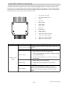
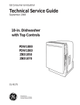
Component Locator Views
Single Double Wall Oven (Profile shown)
Door Lock
Broil Element
Light
Oven Temperature Sensor
Ribbon Cable
Meat Probe Outlet
Convection Fan
Bake Element
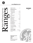
Upper Oven Door Control System (Door shown with inner door assembly removed)
Display/Logic Board
Slider Assembly
– 25 –
(Continued next page)
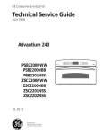
Control Compartment
Back of Oven (Main Rear Panel Shown Removed)
Broil Element
Lock Out Relay
Lower Oven Relay Board
Thermal Cut Out
Upper Oven Relay Board
Thermal Cut Out
Convection Element
Convection Fan
Sail Switch
Bake Element
Cooling Fan
– 26 –
(Continued next page)
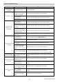
Oven Component Access Chart
WARNING:
•
The wall oven is heavy and requires two people to remove it from the installation. Care should be taken
when removing and installing.
•
Sharp edges may be exposed when servicing. Use caution to avoid injury. Wear Kevlar gloves or
equivalent protection.
l
va
mo
Re
en
ts
Ov
en
on
ng
iri
mp
qu
Co
er
Re
en
ow
ts
L
Ov
en
r
ble
on
pe
ea
mp
Up
vic
Co
er
tS
on
Fr
Bake Element
Broil Element
Convection Bake Element
Convection Fan Blade
Convection Fan Motor
Cooling Fan
Display/Logic Board
Door Assembly
Door Hinge Receiver
Lock Assembly
Lock Out Relay
Meat Probe Outlet
Oven Light Assembly
Oven Temperature Sensor
Relay Boards
Sail Switch Assembly
Thermal Cut Outs
Vent Tube/Smoke Eliminator
– 27 –
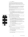
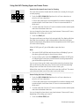
Oven Components
Door Assemblies
Pull down
to access
Upper
Oven
The upper door contains many of the electronics
and controls for the oven.
Lower
Oven
Snap engages
with door
frame
Caution: The doors are heavy. Use the correct lifting
procedure. Do not lift the doors by the handles.
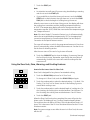
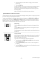
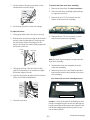
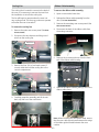
To remove the lower door:
1. Open the door fully.
Slider Assembly
2. Push the hinge locks down toward the door
frame, to the unlocked position. (This may
require a flat-blade screwdriver to start the
hinge locks moving.)
3. Pull the tab forward to release the ribbon cable
assembly from the door.
Slot
Hinge
lock
3. Firmly grasp both sides of the door at the top.
4. Close the door to the door removal position.
Pull down to
disconnect
ribbon cable
assembly
Press tab
to release
ribbon
cable
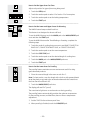
4. Fully open the upper oven door.
5. Lift up on the hinge locks toward the oven frame
until they stop.
Hinge Lock
(Unlocked Position)
Slot
Hinge
Lock
5. Lift the door up and out until the hinge arm is
clear of the slot
6. Close the door to 45 degrees. The hinge lock will
contact the oven frame.
Removal Position
To remove the upper door:
1. Fully open or remove the lower door.
2. Pull down on the ribbon cable until the snap
engages with the door frame.
– 28 –
(Continued next page)
7. On both sides of the door, press down on the
release buttons on each hinge.
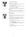
To remove the lower outer door assembly:
1. Remove the lower door. (See Door Assemblies.)
Door
Frame
2. Place the inner door assembly, gasket side up,
on a protective surface.
3. Remove the four T15 Torx screws from the
bottom of the outer door assembly.
Release buttons
8. Lift the door up until it is clear of the hinge.
To replace the door:
1. Firmly grasp both sides of the door at the top.
2. With the door at the same angle as the removal
position, seat the indentation of the hinge arm
into the bottom edge of the hinge slot. The
notch in the hinge arm must be fully seated into
the bottom of the slot.
Bottom
edge
of slot
4. Remove the two T15 Torx screws (1 on each
side) from the outer door assembly.
1 of 2
Hinge arm
Indentation
3. Fully open the door. If the door will not fully
open, the indentation is not seated correctly in
the bottom edge of the slot.
4. Push the hinge locks up against the front frame
of the oven to the locked position.
Note: The inner door assembly is heavier than the
outer door assembly.
5. Separate the inner door assembly from the
outer door assembly.
6. Remove the four 1/4-in. hex-head screws and
brackets that hold the door handle to the outer
door assembly.
Door Shown with Inner Door Assembly Removed
Hinge
lock
Hinge
arm
Outer Door Assembly
5. Close the oven door.
Caution: Care must be taken if reinstalling the door
handle. Overtightening the screws can damage the
handle. Hand-tighten the screws and make sure the
handle fits snugly against the door panel. (Do not
use an electric driver.)
– 29 –
(Continued next page)
To replace the lower inner door assembly:
To remove the upper outer door assembly:
1. Remove the outer door assembly. (See Door
Assemblies.)
1. Remove the upper door. (See Door Assemblies.)
2. Remove the four T15 Torx screws (2 on each
side) that attach each door hinge to the inner
door. Carefully turn the door over and remove
both door hinges.
2. Place the inner door assembly, gasket side up,
on a protective surface.
3. Remove the two T15 Torx screws from the
bottom of the outer door assembly.
4. Remove the two T15 Torx screws (1 on each
side) from the outer door assembly.
1 of 2
3. Remove the six 1/4-in. hex-head screws that
hold the insulation retainer to the inner door.
Remove the insulation retainer.
Note: The inner door assembly is heavier than the
outer door assembly.
5. Separate the inner door assembly from the
outer door assembly.
6. Remove the four 1/4-in. hex-head screws and
brackets that hold the door handle to the outer
door assembly.
Door Shown with Inner Door Assembly Removed
4. Remove the insulation and the inner glass
assembly from the inner door.
Outer Door Assembly
Inner Glass Assembly
Caution: Care must be taken if reinstalling the door
handle. Overtightening the screws can damage the
handle. Hand-tighten the screws and make sure the
handle fits snugly to the door panel. (Do not use an
electric driver.)
– 30 –
(Continued next page)
To replace the upper inner door assembly:
Assembly Notes
1. Remove the upper door assembly. (See Door
Assemblies.)
When assembling, make sure the hinges are parallel
to each other and perpendicular to the door liner. If
not, the hinge may bind on the receiving channel of
the door. If the new hinge is not in the cocked and
locked position after installing, place the bottom of
the door against a firm, protected surface and push
the hinge arm down to the cocked position. Pull the
hinge lock back against the door liner surface to
lock the hinge in this position.
2. Remove the four T15 Torx screws (2 on each
side) that attach each door hinge to the inner
door. Carefully turn the door over and remove
both door hinges.
Air enters the door assembly through large slots in
the bottom and flows upward between the inner
and outer assemblies, exhausting through slots
in the top of the door. DO NOT INSULATE THIS AIR
CHANNEL.
Door Gasket
3. Remove the six 1/4-in. hex-head screws that
hold the insulation retainer to the inner door.
Remove the insulation retainer.
The gasket forms a complete seal around the front
edge of the oven liner and the inner door panel. The
door gasket is attached to the inner door panel by
spring clips. When removing the gasket, pull the
ends of the gasket out of the slots at the bottom
of the door. Place a finger under the gasket beside
each clip and pull straight up.
4. Remove the insulation and the inner glass
assembly from the inner door.
Inner Glass Assembly
When installing the door gasket, it is helpful to fold
the gasket in half and locate the center clip. Insert
the clip at the top of the door and work your way
around the door.
Make sure the gasket is cross-tucked in the
bottom slots of the inner door panel. Use a small
screwdriver to tuck the loose ends of the gasket into
the slots. The overlap is required to ensure a proper
door seal.
Cross Tuck
– 31 –
Door Shown with Inner Door Assembly Removed
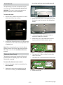
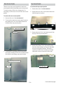
Oven Removal
The replacement of certain components require
oven removal. (See Oven Component Access Chart.)
WARNING: The oven is heavy and requires two
people to remove it from the installation.
To remove the oven:
Outer Door Assembly
1. Remove the 2 Phillips-head screws (1 on each
side) that hold the oven in place.
3. Remove the three 1/4-in. hex-head screws from
the plastic cover that protects the display/logic
boards.
4. Lift the bottom edge of the plastic cover to
expose the display/logic boards.
5. Remove the 1/4-in. hex-head screw from the
logic board that holds the board in place.
2. Pull the oven forward to remove it. Utilize a table
or platform in front of the oven and pull the oven
completely out.
Note: When reinserting the oven into the cabinet
opening, ensure the conduit is properly positioned
behind the oven. (See the Installation Instructions
manual.)
Electronic Oven Control
The electronic oven control consists of the touch
glass keyboard, the display/logic board, and the
slider board assembly.
6. Disconnect the 2 ribbon cables from the right
side of the board.
7. Disconnect the 2 wire harnesses from the board.
To remove the electronic oven control:
Disconnect
Disconnect
1. Remove the upper outer door assembly. (See
Door Assemblies.)
Disconnect
Disconnect
2. Separate the inner door assembly from the
outer door assembly. (See Door Assemblies.)
8. Remove the board.
– 32 –
(Continued next page)
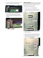
9. To access the slider board assembly, remove the
3/8-in. nut securing the insulating cover.
Side Access Panels
There are two side panels on each side of the oven.
To remove the side access panels:
1. Remove the oven. (See Oven Removal.)
2. On each side of the oven, remove the four 1/4in. hex-head screws that hold the side trim in
place.
10. To remove the board from the slider board
assembly, press the two tabs securing the
board to the slider and lift the board from the
assembly.
Panel One
Side Trim
Panel Two
Left Side Shown
3. Remove the two T10 Torx screws that hold the
bracket to the oven.
4. Remove the 1/4-in. hex-head screws that hold
the two side panels to each side of the oven.
There are 46 hex-head screws on the left side
and 41 screws on the right side.
1 of 46
To
r
xS
cre
w
Bracket
rew
rx
To
Left Side Shown
– 33 –
Sc
Rear Access Panels
Top Access Panels
There are two rear access panels: the main rear
access panel and the secondary rear access panel.
To remove many of the oven components, it is
necessary to remove one or both of the rear access
panels.
To remove the top access panels:
1. Remove the oven. (See Oven Removal.)
2. Remove the four 1/4-in. hex-head screws that
hold the top trim in place.
To remove the rear access panels:
1. Remove the oven. (See Oven Removal.)
2. To remove the main rear access panel, remove
the twenty-five 1/4-in. hex-head screws that
hold the main rear panel in place.
Main Access Panel
1 of 25
3. To remove the secondary rear access panel,
remove the twenty-five 1/4-in. hex-head screws
that hold the secondary rear panel in place.
3. Remove the two 1/4-in. hex-head screws from
the top of the top access panel.
4. Remove the fifteen 1/4-in. hex-head screws
from the sides and back of the oven that hold
the top access panel in place. There are 4
screws on the left side, 3 screws on the right
side and 8 screws on the back of the oven.
1 of 15
Secondary Access Panel
Right Side Shown
1 of 25
– 34 –
(Continued next page)
5. Remove the thirteen 1/4-in. hex-head screws
from the top of the heat shield.
4. Carefully pull the sensor and sensor wiring
harness from the oven liner.
Note: When reinstalling the sensor, use a small flatbladed screwdriver to push and guide the sensor
wire harness into the oven liner.
1 of 13
6. Lift up the top heat shield.
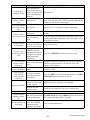
Broil Element
Oven Temperature Sensor
•
1080 Ω at room temperature
The broil element will not work if the temperature
probe is plugged in. The broil element terminals are
located behind the main rear access panel.
•
2650 Ω at clean temperature
The broil elements are rated at:
The resistance of the temperature sensor is:
To remove the oven temperature sensor:
•
Upper oven broil element (inner) - 1700 watts
1. Remove the main rear access panel. (See Rear
Access Panels.)
•
Upper oven broil element (outer) - 1050 watts
•
Lower oven broil element (inner) - 2200 watts
2. Remove the two 1/4-in. hex-head screws that
attach the sensor to the broiler element bracket.
•
Lower oven broil element (outer) - 750 watts
To remove the broil element:
1. Remove the main rear access panel. (See Rear
Access Panels.)
IMPORTANT: The lower wattage elements use
3/16-in. terminal connections. The higher wattage
elements use 1/4-in. terminal connections.
2. Disconnect the wires from the broil element.
Disconnect
ne
on
sc
Di
Di
sc
sc
on
ne
ct
on
ne
ct
Di
Di
sc
on
ne
ct
ct
3. Disconnect the sensor wiring harness from the
back of the oven.
3. Remove the two 1/4-in. hex-head screws that
attach the temperature sensor to the broiler
element bracket.
– 35 –
(Continued next page)
4. Remove the three 1/4-in. hex-head screws
that attach the broiler element to the oven
cavity.
5. Carefully pull out the sensor approximately 2
inches from the broiler element bracket.
6. Remove the four 1/4-in. hex-head screws that
attach the broil element to the top of the oven.
3. Remove the two 1/4-in hex-head screws that
hold the bake element to the back of the oven.
4. Carefully pull the bake element out through the
front of the oven.
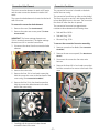
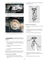
Convection Fan Blade
The convection fan blade is located on the back wall
of the oven cavity and is removed separately from
the convection fan motor.
To remove the convection fan blade:
1. Remove the oven racks.
7. Carefully pull, then lower the broiler element
towards the front of the oven to remove.
2. Remove the four 1/4-in. hex-head screws that
hold the convection cover to the back wall of the
oven cavity.
Bake Element
The upper bake element is rated at 1700 watts, and
the lower element is rated at 2200 watts.
The bake element terminals are located behind the
main rear access panel.
To remove the bake element:
1. Remove the main rear access panel. (See Rear
Access Panels.)
IMPORTANT: The lower wattage elements use
3/16-in. terminal connections. The higher wattage
elements use 1/4-in. terminal connections.
3. The fan blade is attached to the motor shaft
with a reverse-threaded 1/2-in. hex-nut. Turn
the nut clockwise to remove.
2. Disconnect the wires from the bake element.
Disconnect
Disconnect
– 36 –
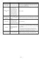
Convection Bake Element
Convection Fan Motor
The inner convection element is rated at 655 watts
and the outer convection element is rated at 645
watts.
The convection fan motor is located on the back
wall of the oven cavity.
The convection bake element is located on the back
wall of the oven.
To remove the convection bake element:
The convection fan will turn on (after a short delay).
The fan may cycle on and off, and change direction,
to best distribute hot air in the oven. The convection
fan shuts off when the door is opened.
The convection fan motor has approximate
resistance values between the following wires:
1. Remove the oven. (See Oven Removal.)
2. Remove the main rear access panel. (See Rear
Access Panels.)
IMPORTANT: The lower wattage elements use
3/16-in. terminal connections. The higher wattage
elements use 1/4-in. terminal connections.
•
Red and Blue: 168 Ω
•
Red and Gray: 75 Ω
•
Blue and Gray: 93 Ω
To remove the convection fan motor assembly:
3. Disconnect the wires from the convection bake
element.
1. Remove convection fan blade. (See Convection
Fan Blade.)
2. Remove the rear access panel. (See Rear Access
Panels.)
3. Disconnect the convection fan motor wire
harness.
4. Remove the three 1/4-in. hex-head screws that
hold the convection fan motor to the back of the
oven.
4. Remove the oven racks.
5. Remove the four 1/4-in. hex-head screws that
hold the convection cover to the back wall of the
oven cavity. (See Convection Fan Blade.)
6. Remove the five 1/4-in. hex-head screws that
hold the convection bake element to the back
wall of the oven cavity.
Disconnect
7. Carefully pull the convection bake element
toward the front of the oven.
– 37 –
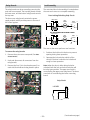
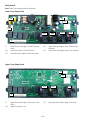
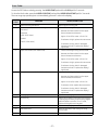
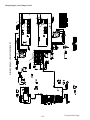
Relay Boards
Lock Assembly
The relay boards can be accessed by removing the
main rear access panel. The top relay board controls
the lower oven, and the bottom relay board controls
the top oven.
The motorized door lock assembly is located above
the oven and comes as a complete assembly.
Door Locking/Unlocking Strip Circuit
The lower oven relay board contains the power
supply module, which provides power to the rest of
the control system.
LOCK RELAY
LOCK
MOTOR
L
J14
DOOR
SWITCH
NO
C
J7
N
NC
ALL OTHER MODES WITH DOOR CLOSED
Lower Oven Relay Board
LOCK RELAY
LOCK
MOTOR
L
J14
DOOR
SWITCH
NO
C
J7
Upper Oven Relay Board
N
NC
The cam on the motor performs two functions:
To remove the relay boards:
1. Remove the main rear access panel. (See Rear
Access Panels.)
2. Mark and disconnect all connectors from the
relay boards.
3. Remove the four 1/4-in. hex-head screws (2 on
each side) that hold each relay board in place.
1. Positions the lock hook in the door to prevent
opening during clean operation.
2. Operates the lock switches, which tell the
control if the door is unlocked or locked and
ready for clean operation.
Note: When the door is either being locked or
unlocked, both the lock and unlock switches will
be in the open position. The upper oven latch is
controlled by the upper oven relay board. The lower
oven latch is controlled by the lower oven relay
board.
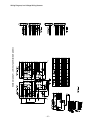
Strip Circuit
LOCKED
J16
5
4
3
2
1
J17-Pin9
– 38 –
(Continued next page)
Strip Circuit
Thermal Cut Outs
When either of the 2 thermal cut outs are open, L2 is
cut off from the oven.
J16
UNLOCKED
5
4
3
2
1
The thermal cut outs are rated at:
•
Upper oven TCO = 177°C/350°F
•
Lower oven TCO = 150°C/302°F
J17-Pin9
To remove the lock assembly:
Upper Oven Thermal Cut Out
1. Remove the main rear access panel. (See Rear
Access Panels.)
2. Remove the two T15 Torx screws from the front
of the oven that secure the lock assembly in
place.
Lower Oven Thermal Cut Out
3. Disconnect the motor and switch wiring
harnesses from the lock assembly.
To remove the thermal cut outs:
Disconnect
Lock Assembly
1. Remove the main rear access panel. (See Rear
Access Panels.)
2. Disconnect the wires, and remove the two 1/4in. hex-head screws that attach the thermal
switch to the oven.
Disconnect
4. Slide the lock assembly through the channel and
out through the back of the oven.
Disconnect
Disconnect
Disconnect
Disconnect
– 39 –
Micro Switch
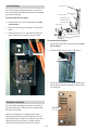
Lock Out Relay
The L2 DLB lockout relay opens the L2 side of the
line to the upper oven heating elements if the upper
oven door is opened.
Sail
To remove the lock out relay:
Airflow from the
Cooling Fan Pulls
the Sail Closed
1. Remove the main rear access panel. (See Rear
Access Panels.)
Cooling Fan
2. Mark and disconnect the wiring to the lock out
relay.
3. Remove the two 1/4-in. hex-head screws that
attach the lock out relay to the oven frame.
To remove the sail switch:
1. Remove the main rear access panel. (See Rear
Access Panels.)
2. Disconnect the wires from the sail switch.
Disconnect
Disconnect
Disconnect
1
3. Remove the two 1/4-in.
hex-head screws that
attach the sail switch assembly to the left side
access panel.
Sail Switch Assembly
The sail switch assembly is located on the back of
the unit, above the cooling fan, and is operated by
the airflow of the fan.
Sail Switch
When the cooling fan is in high speed, the sail
should be closed. When the cooling fan is off, the
sail should be open. When the cooling fan is in low
speed, the sail may be open or closed, and the
control ignores the output of the micro switch.
– 40 –
Cooling Fan
Ribbon Cable Assembly
The cooling fan is located in a recess in the back of
the oven. It is necessary to remove the oven from
the installation to access the cooling fan.
To remove the ribbon cable assembly:
The fan will begin to operate when the oven is in
any cooking mode. The fan may continue to operate
even after the oven is turned off.
2. Release the ribbon cable assembly from the
door. (See Door Assemblies.)
1. Open or remove the lower door.
To remove the cooling fan:
3. Remove the secondary rear access panel. (See
Rear Access Panels.)
1. Remove the main rear access panel. (See Rear
Access Panels.)
4. Disconnect the back of the ribbon cable from
the mating connector.
2. Disconnect the wire harness and the ground
wire from the cooling fan.
Disconnect
Disconnect
Disc
onn
ect
Cooling Fan
5. Remove the 4 screws and nuts from the front
end of the ribbon cable housing.
3. Remove the four 1/4-in. hex-head screws (2
on each side) that hold the cooling fan to the
control compartment.
6. Remove the ribbon cable by sliding it out of the
ribbon cable sleeve.
4. Carefully grasp the assembly and tilt the unit
back, up, and out of the oven frame.
Note: When installing the new ribbon cable, ensure
that the new cable is positioned between the wings
of the ribbon guide located between the oven
cavities.
– 41 –
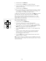
Door Hinge Receivers
To remove the door hinge receivers:
1. Remove the side access panels. (See Side Access
Panels.)
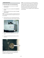
3. Pull the outlet and wiring down from the oven
wall.
Note: When replacing the meat probe outlet, cut
the probe wires and splice the new probe using
approved heat-resistant connectors.
2. Carefully lift the insulation from the outside of
the oven.
3. Remove the two T20 Torx screws that hold each
hinge receiver to the oven frame.
Cut Here
Cut Here
4. Push the hinge receiver through the opening in
the oven frame and remove from the rear.
Note: Upon reassembly, ensure the displaced
insulation around the oven and components is
returned to its original position.
Meat Probe and Outlet
The meat probe outlet is located on the top of the
oven cavity, near the front. The meat probe outlet is
connected to the electronic oven control. The meat
probe has a resistance value of 30K-50K Ω at room
temperature.
To remove the meat probe outlet:
1. Open the lower oven door.
2. Remove the two 1/4-in. hex-head screws that
attach the meat probe outlet to the top of the
oven cavity.
Oven Light Assembly
The oven has two light assemblies in each oven
cavity. The light assemblies are located on the top
rear of the oven. The lights come on when the door
is opened or when the oven is in a cooking cycle.
The oven lights do not come on during self-cleaning
or if the Sabbath Feature is set.
Each light assembly consists of a removable light
cover, a light bulb socket, and a light bulb.
To remove an oven light assembly:
1. Remove the main rear access panel. (See Rear
Access Panels.)
2. Remove the three 1/4-in. hex-head screws that
attach the panel securing the lighting assembly
wires to the rear of the oven.
– 42 –
(Continued Next Page)
3. Disconnect the light assembly wire harness.
2. Using gloves or a dry cloth, remove the bulb by
pulling straight out.
Socket
Receptacle
Disconnect
3. Open the oven door and remove the two 1/4-in.
hex-head screws that attach the light housing to
the oven liner.
Bulb
Tab
Glass cover
To replace the oven light bulb:
1. Use a new 130-volt halogen bulb, not to exceed
50 watts.
2. Using gloves or a dry cloth, remove the bulb
from its packaging. Do not touch the bulb with
bare fingers.
3. Push the bulb straight into the receptacle.
4. Pull the oven light housing from the oven liner.
Oven Light Bulbs
CAUTION:
Receptacle
•
Before replacing the oven light bulb, disconnect
the electrical power to the oven at the main fuse
or circuit breaker.
•
Be sure to let the light cover and bulb cool
completely.
•
Do not touch a hot bulb with bare hands or a
damp cloth.
Use gloves
or cloth
Note: The glass cover should be removed only when
cold. Wearing latex gloves may offer a better grip.
To remove the oven light bulb:
4. Place the tabs of the glass cover into the
grooves of the socket. Turn the glass cover CW
1/4 turn.
1. Turn the glass cover CCW 1/4 turn until the
tabs of the glass cover clear the grooves of the
socket.
5. Reconnect electrical power to the oven.
– 43 –
Smoke Eliminators
To remove the upper oven smoke eliminator:
1. Remove both rear access panels. (See Rear
Access Panels.)
2. Remove the top access panels. (See Top Access
Panels.)
Note: To access the lower oven smoke eliminator,
the two ovens must be separated. To separate the
upper and lower ovens, it is necessary to remove
all 4 side access panels and remove the 2 metal
brackets (1 on each side) at the front of the unit
that secure the two ovens together. Wiring that
connects the 2 ovens together must be marked and
disconnected.
3. Remove both left side access panels. (See Side
Access Panels.)
Note: To access the vent tube, it may be necessary
to cut and fold the insulation away from the top of
the oven liner.
4. Remove the two 1/4-in. hex-head screws that
secure the vent tube to the top of the oven liner.
Vent Tube
5. Pull the vent tube straight up and out of the
oven.
6. Pry the smoke eliminator from the top of the
oven liner.
Smoke Eliminator
Note: Upon reassembly, ensure the displaced
insulation around the oven and components is
returned to its original position.
– 44 –
Electronic Oven Control
Oven Circuits
L2
L2
Relay*
L1
Relay*
UPPER OVEN
BAKE & SELF CLEAN
L1
UPPER OVEN
BROIL
K14
DLB
K14
DLB
BAKE
INNER BROIL
K7
K3
INNER BROIL
K3
ON/OFF
N
SPEED
HIGH
OUTER BROIL
K5
K8
ON/OFF
LOW
K4
M
COOLING FAN
N
SPEED
HIGH
K5
LOW
K4
M
COOLING FAN
L1
L2
LOWER OVEN
BROIL
L1
L2
LOWER OVEN
SELF CLEAN
K14
DLB
K14
DLB
BAKE
INNER BROIL
K7
K3
INNER BROIL
OUTER BROIL
K3
K8
OUTER BROIL
ON/OFF
N
SPEED
K8
HIGH
K5
LOW
K4
M
ON/OFF
COOLING FAN
N
SPEED
HIGH
K5
LOW
K4
M
COOLING FAN
L1
L2
LOWER OVEN
BAKE & CONVECTION ROAST
L1
L2
LOWER OVEN
CONVECTION BAKE
K14
DLB
K14
DLB
NOT USED DURING PREHEAT
BAKE
CONVECTION
K7
K10
INNER BROIL
BAKE
K3
K7
ONLY USED DURING PREHEAT
OUTER BROIL
INNER BROIL
K8
K3
ONLY USED DURING PREHEAT
ON/OFF
N
SPEED
OUTER BROIL
HIGH
K5
K4
LOW
K8
M
COOLING FAN
ON/OFF
ON/OFF
HIGH
CCW
K5
K4
N
SPEED
DIRECTION
CW
K5
M
K4
LOW
M
COOLING FAN
CONVECT FAN
ON/OFF
DIRECTION
CCW
K5
K4
CW
M
CONVECT FAN
All closed switches shown above are closed during the respective cooking cycle. All open switches cycle
during the respective cooking cycle.
Note:
•
Relay – This relay is external to the control boards and is mounted on the back cover of the unit. This
relay is connected to the upper plunger switch and opens and closes based on the plunger position.
•
Element Relay Cycling – All cavity elements cycle during preheat and once the oven cooking
temperature is reached. However, only the bake, inner broil, and convection elements come on one at a
time (multiple elements are not energized).
•
Power Sharing Mode – The outer broil elements are disabled when both ovens are in operation.
•
Relay/Board Designations – All relays listed above for each oven correspond to their respective oven
relay boards except for the cooling and convection fans. The cooling fan is located on the upper oven
relay board, and the convection fan is located on the lower oven relay board.
– 45 –
Relay Boards
Note: There is one relay board for each oven.
Lower Oven Relay Board
J20
J16
J17
J21
Broil
Bake
CONVX
DLB
J7
J7
Lower Oven: Oven Light, CONVX Fan, Lock
Motor
J20
Lower Oven and Upper Oven: Thermal Limit
Switches
J16
Lower Oven Door Lock, Sail Switch
J21
Lower Oven and Upper Oven: Door Switches
J17
Communication Cable, Lower Oven Clean
Upper Oven Relay Board
J16
J17
Broil
Bake
DLB
J7
J7
Upper Oven: Oven Light, Cooling Fan, Lock
Motor
J16
Upper Oven Door Lock
J17
– 46 –
Communication Cable, Upper Oven Clean
Electronic Oven Control
J1
J5
J1
Wire Harness to Interface Board
J5
Wire Harness to Interface Board
Electronic Oven Control (Shown attached to Glass Touch Interface)
J1
J5
J1
Wire Harness to Interface Board
J5
Wire Harness to Interface Board
– 47 –
Diagnostics and Service Information
Control Voltage
WARNING: Components are electrically HOT on control when voltage is connected to oven. To prevent electrical
shock, use extreme caution when diagnosing oven with outer covers removed and power on.
Note: Mode and temperature selection is necessary for operation of relay contacts. This model incorporates
Double Line Break, meaning there is no voltage on the elements when the control is in standby.
Terminals on
ERC (element
terminals are
on top of large
relays)
J20 (Pins 1 to
Pins 3)
J14 to J11
J14 to J20 (red
wire)
J14 to Broil
(violet wire on
K3)
J14 to Conv.
(blue wire on
K10 Lwr oven
relay board
only)
J14 to Bake
(yellow wire on
K7)
J14 to DBL
(orange wire
on K14)
Voltage,
standby
Voltage, broil
mode active
(either oven)
Voltage, bake
upper oven
Voltage, bake lower oven
No relays
should be
energized in
standby
Only broil and DLB
relay activate
Broil and bake
elements cycle
Broil and bake elements cycle
convect fan is on
120V (if not, harness may be bad*
120V (if not, harness may be bad*
120V (if not, harness may be bad*
˜OVAC
˜OVAC (Broil on)
˜OVAC (Broil on)
˜240 VAC (Broil off)
˜240 VAC (Broil off)
N/A
˜OVAC (Conv. on)
˜240 VAC
˜240 VAC (Conv. off)
˜240 VAC
˜240 VAC
˜240 VAC (Bake
off)
˜OVAC (Bake on)
˜240 VAC
˜240 VAC (Bake off)
˜OVAC (Bake on)
˜240 VAC
* These wires supply the main power to the control. Check harness if these voltages are not present.
– 48 –
(Continued Next Page)
Wires on J7 (below small relays)
Brown to White
Blue to J11 (Lwr oven relay board only)
Black jumper to J11
Red to J11 (Lwr oven relay board only)
Violet with white to J11
Black to J11
White with Black to J11 (Upr oven relay
board only)
White with Red to J11 (Upr oven relay
board only)
0 ohms when oven light is on
120V when convection fan turns CCW
120V when convection fan is on
120V when convection fan turns CW
120V when broil element is on
120V when oven door latch is activated
120V when cooling fan is in high speed
120V when cooling fan is in low speed
– 49 –
(Continued Next Page)
Service Mode
The oven control has a service mode that can be utilized by the service technician in order to test critical
components and to access error codes. This service mode will help the service technician to quickly identify
failed or improperly operating oven components.
To enter the service mode:
To exit the service mode:
1. Press and hold the Upper BAKE pad and the
BROIL pad until “SF” appears in the display.
2. Then press and hold the 1 and 5 pads until
“Product TEST” appears in the display.
Press and hold the Upper START pad for 3 seconds.
Note: If no key is pressed for 5 minutes, the oven
control will automatically exit the Service Mode.
Once in the Service Mode, the functionality of
the key pads and the functions of the oven may
be checked using the table below.
Keypad
U/L BAKE
U/L BROIL
U/L SELF CLEAN
U/L WARM/PROOF
U/L DELAY START
LED
On
On
On
On
On
Display
"Product TEST"
"Product TEST"
"UnL", "Loc", or "trA"¹
"Product TEST"
Software revision
Oven Function
Turn bake element on
Turn broil elements on
Rotate door lock motor
Toggle cooling fan speed
Key Pad Test Only
U/L START
On
"Product TEST"
Key Pad Test Only
U/L COOK TIME
U/L OVEN LIGHT
U/L CLEAR/OFF
SLOW COOK
On
On
Oven sensor temps²
All LEDs turn on
"Product TEST"
"Product TEST"
Key Pad Test Only
Turn cavity lights on
Cancel current function
Key Pad Test Only
"Product TEST"
Turn conv. element on
On
"Product TEST"
Turn conv. fan on
On
On
On
On
On
"Product TEST"
"Product TEST"
All LEDs turn on
Probe temp³
Sail switch status
1 2 3 4 5 6 7 8 9 0
Key Pad Test Only
Key Pad Test Only
Key Pad Test Only
Key Pad Test Only
Toggle cooling fan speed
Key Pad Test Only
On
CONVECTION BAKE On
CONVECTION
ROAST
PIZZA
TIMER
CLOCK
PROBE
HELP
NUMBER KEYS
(1) UnL = Unlocked, Loc = Locked, trA = Travel
(2) Open circuit = 930˚F, short circuit = 32˚F
(3) Open circuit = 99˚F, short circuit = 203˚F
– 50 –
Using the Ribbon Cable for Troubleshooting
The ribbon cable allows the technician to inspect several key signals without removing the wall oven from
the cabinet. To access the ribbon cable, remove the ribbon cable from the upper oven door as described in a
previous section. The plastic housing at the end of the ribbon cable is marked with a 1 and 14. These marks
identify the position of the signals within the ribbon cable.
Problem
1
DC Common (Ground)
2
LIN Communication Line
3
12VDC
4
Not Used
5
Relay Enable
6
Clean Upper
7
Clean Lower
8
Not Used
9
Probe Signal
10
Probe Ground
11
Lower Oven Sensor Ground
12
Lower Oven Sensor Signal
13
Upper Oven Sensor Ground
14
Upper Oven Sensor Signal
Possible Causes
What To Do
If Special Features can be accessed, verify the clock is not
Special Features setting
turned off.
Circuit breaker
Verify circuit breaker is not tripped.
• Remove ribbon cable from the upper door.
•
If 12VDC is between pin 1 and pin 3, check door wiring
and display/logic board.
•
If 12VDC is NOT between pin 1 and pin 3, advance to
the next step.
Remove the unit from the cabinet.
12VDC to door
Nothing in the
display
•
House wiring
12VDC supply
•
Confirm the wiring and power to the conduit is
correct.
If 12VDC is NOT between pin 1 and pin 3 of J17 on
the main relay board, inspect the wiring harness and
connections; otherwise, replace the lower oven relay
board.
– 51 –
(Continued Next Page)
Problem
Possible Causes
Plunger switch
What To Do
If the cavity lights are always on, check the plunger switch
related to the bad cavity.
• Test the functions in Service Mode.
Relay (upper cavity
only)
•
•
Wiring or heating
Cooking functions element
do not work
•
•
Display/logic board
•
•
Oven relay board
Plunger switch
Oven cavity lights
not working
properly
Wiring
Oven relay board
Glass touch key panel
Keypad or LED not
working
Ribbon cable or
display/logic board
If the cooling fan, sail switch, and lights work properly,
check the relay and associated wiring.
Test the functions in Service Mode.
If relays click to turn on the heating elements but
no heat is generated, check the wiring and heating
element resistance.
Test the functions in Service Mode.
If none of the functions in Service Mode work properly,
replace the display/logic board.
Test the functions in Service Mode.
•
If some of the functions work and others do not, check
the relay board that is not working.
If the cavity lights are always on, check the plunger switch
related to the bad cavity.
If the lights work properly using the keypad but not
opening and closing the door, check the wiring to J20 on
the lower oven relay board.
If lights do not work for a specific cavity, check the wiring
and relay board associated with that cavity.
If only a single keypad or LED does not work, replace the
glass touch key panel.
If multiple keypads or LEDs do not work, check the ribbon
cable or replace the display/logic board.
– 52 –
Convection Fan Troubleshooting
Problem
Fan motor buzzes
No fan operation
Fan loud
Possible Causes
Open capacitor
Open winding as
indicated by ohm
check red to black and
blue to black (approx.
60 ohms each)
Check voltage CCW
to N when fan is CCW
- should read 120VAC
in Convection Bake.
Also, CW to N when CW
as indicated by ERC
display
Shaft or blade rubbing
on oven liner
Jamb switch NC to C is
open
Loose shaft nut
Loose convect cover
screws or cavity screws
What To Do
Harness, terminals, or bad capacitor.
Replace motor.
•
If no voltages, replace ERC.
•
If voltages OK, check harness or winding resistance.
Loosen screws/re-adjust position/tighten.
Replace jamb switch or check harness.
Tighten shaft nut. Do not bend blade.
Tighten screws. Use larger screw if stripped.
Oven Sensor Ohmmeter Test
Remove ribbon cable from the upper oven door. Make resistance measurements of the sensors with the
exposed terminals of the ribbon cable.
Upper Oven
Sensor
Lower Oven
Sensor
Pin 13 to pin 14
Pin 11 to pin 12
Room temp - 1080 ohms
Clean temp - 2650 ohms
– 53 –
General Troubleshooting
Problem
Oven light does
not work
Oven will not work
Food does not
bake or roast
properly
Food does not broil
properly
Oven temperature
too hot or too cold
Clock and timer do
not work
Oven will not selfclean
Possible Causes
Light bulb is loose
A fuse in the home may
be blown or the circuit
breaker is tripped
Oven controls
improperly set
Oven is too hot
Oven controls
improperly set
Rack position is
incorrect or the rack is
not level
Incorrect cookware or
cookware of improper
size being used
Oven thermostat needs
adjustment
Oven controls
improperly set
Improper rack position
used
Cookware not suited
for broiling
The probe is plugged
into the outlet in the
oven
In some areas, the
power (voltage) may be
low
Oven thermostat needs
adjustment
A fuse in the home may
be blown or the circuit
breaker tripped
Oven controls
improperly set
The oven temperature
is too high to set a selfclean operation
Oven controls
improperly set
The probe is plugged
into the outlet in the
oven
What To Do
Replace the bulb.
Replace the fuse or reset the circuit breaker.
See the Using the Upper and Lower Ovens section.
Allow the oven to cool to below locking temperature.
See the Using the Upper and Lower Ovens section.
See the Using the Upper and Lower Ovens section.
See the Using the Upper and Lower Ovens section.
See the Adjusting the Upper or Lower Oven Thermostat
section.
Make sure you touch the BROIL HI/LO pad.
Adjust the rack position.
For best results, use a pan designed for broiling.
Unplug and remove the probe from the oven.
•
Preheat the broil element for 10 minutes.
•
Broil for the longest period of time recommended.
See the Adjusting the Upper or Lower Oven Thermostat
section.
Replace the fuse or reset the circuit breaker.
See the Using the Clock, Kitchen Timer, and Control Lock
section.
Allow the oven to cool and reset the controls.
See the Using the Self-Cleaning Upper and Lower Ovens
section.
Remove the probe from the oven.
– 54 –
(Continued Next Page)
Problem
Possible Causes
What To Do
This is the sound of
the metal heating and
"Crackling" or
cooling during both the This is normal.
"popping" sound
cooking and cleaning
functions
Excessive smoking
Touch the CLEAR/OFF pad. Open the windows to rid the
during a clean
Excessive soil
room of smoke. Wait until "LOCKED" goes off. Wipe up the
cycle
excess soil, and reset the clean cycle.
Oven door will not
open after a clean Oven too hot
Allow the oven to cool below locking temperature.
cycle
Oven controls not
See the Using the Self-Cleaning Upper and Lower Ovens
properly set
section.
Oven not clean
Clean up heavy spill-overs before starting the clean cycle.
after a clean cycle Oven was heavily
Heavily soiled ovens may need to self-clean again or for a
soiled
longer period of time.
The self-clean cycle
"LOCKED" flashes
has been selected, but Close the oven door.
in the display
the door is not closed
The oven door is
locked because the
"LOCKED" is on
temperature inside the
Touch the CLEAR/OFF pad. Allow the oven to cool.
when you want to
oven has not dropped
cook
below the locking
temperature
"F - and a number
Disconnect all power to the oven for at least 30 seconds,
There is a function error
or letter" flash in
and then reconnect power. If the function error code
code
the display
repeats, call for service.
"LOCKED" appears The controls have been See the Using the Clock, Kitchen Timer, and Control Lock
in the oven display locked
section to unlock.
Control signals
You forgot to enter a
after entering
Touch the BAKE pad and desired temperature or the SELF
bake temperature or
cooking time or
CLEAN HI/LO pad and desired clean time.
cleaning time
start time
A fuse in the home may
be blown or the circuit Replace the fuse or reset the circuit breaker.
Display goes blank breaker tripped
The clock is in the
See the Special Features of the Oven Control section.
black-out mode
Display flashes
Power failure
Reset the clock.
Unable to get the
Oven control pads were The BROIL HI/LO pad and the BAKE pad must be touched
display to show
not touched properly
at the same time and held for 3 seconds.
"SF"
This is reminding
"Probe" appears in you to enter a probe
Enter a probe temperature.
the display
temperature after
plugging in the probe
– 55 –
(Continued Next Page)
Problem
Possible Causes
Power outage,
clock flashes
Power outage or surge
When using the ovens,
it is normal to see
steam coming out of
the oven vents. As the
Steam from the
number of racks or
vent
amount of food being
cooked increases,
the amount of visible
steam will increase
Burning or oily
This is normal in a new
odor emitting from oven and will disappear
the vent
in time
An odor from the
insulation around the
Strong odor
inside of the oven is
normal for the first few
times the oven is used
What To Do
Reset the clock. If the oven was in use, you must reset it
by touching the CLEAR/OFF pad, setting the clock, and
resetting any cooking function.
This is normal.
To speed the process, set a self-clean cycle for a minimum
of 3 hours. See the Using the Self-Cleaning Oven section.
This is temporary.
•
Fan noise
Oven racks are
difficult to slide
A convection fan may
automatically turn on
and off
This is normal. To maximize cooking evenness, the fan
is designed to operate in both directions, with a pause
in between.
•
The convection fan will operate during preheat of
the bake cycle. The fan will turn off after the oven is
heated to the set temperature. This is normal.
Apply a small amount of vegetable oil to a paper towel
The racks were cleaned
and wipe the edges of the oven racks with the paper
in a self-clean cycle
towel. Do not spray with Pam® or other lubricant sprays.
– 56 –
Error Codes
Access the ERC failure codes by pressing the UPPER START pad and the CLOCK pad for 3 seconds.
To clear the fault codes, press the UPPER COOK TIME pad and the UPPER DELAY START pad for 3 seconds.
The oven may stop operating but not immediately give and F code on the display.
FAILURE
CODE
MEANING
CAUSE/CORRECTION
F0
Glass touch key pad failure
Replace glass touch key pad.
F2
Oven temperature inside oven cavity as measured by •
the sensor:
•
Unlocked:
>650° (2237 ohms)
Locked:
>915°F (2724 ohms)
F3
F4
Open oven sensor (over 2850 ohms)
Shorted oven sensor (under 950 ohms)
Check for bad signal using Service Mode.
Remove the ribbon cable from the upper
door and measure resistance:
•
Upper = Pins 13/14; Lower = Pins 11/12
•
If resistance is high, replace the oven sensor.
•
If resistance is okay, look for damaged
harness terminals or replace the display/
logic board.
•
Check for bad signal using Service Mode.
•
Remove the ribbon cable from the upper
door and measure resistance.
•
Upper = Pins 13/14; Lower = Pins 11/12
•
If resistance is low, replace the oven sensor.
•
If resistance is okay, look for damaged
harness terminals or replace the display/
logic board.
F5
Display/logic board failure
Replace the display/logic board.
F7
Shorted key
Determine if problem is with glass touch keypad
or display/logic board by disconnecting keypad
cable and power up control. If no F7 code,
problem is with glass touch keypad.
F8
EEPROM failure
Replace the display/logic board.
F9
Sail switch error
Check the sail switch and cooling fan using
Service Mode.
FC
Door lock error
Check the door lock motor using Service Mode.
– 57 –
Schematics and Wiring Diagrams
WARNING: Disconnect electrical power before servicing.
Caution: Label all wires prior to disconnection. Wiring errors can cause improper and dangerous operation. Verify
operation after servicing.
– 58 –
(Continued Next Page)
14
1
2
1
2
BK
BK
1
1
J5
BK
GY+W
W
3
JAMB SWITCH
(LWR DOOR SENSE)
8
RIBBON
CABLE
1
2
3
1
2
3
BK
BK
BU+O
BK
R+O
W+BK
W+R
O+BK
W
W
Y+W
BK+W
R
5
8
4
7
GY
BR
BR
2
1
2
2
1
8
9
W
W
W
GY
LWR OVEN
SENSOR
LWR OVEN
LIGHT
LIMIT
SWITCH
5
6
9
6
3
2
7
8
9
9
8
7
3
4
5
1
6
1
W
2
6
3
3
5
2
1
2
2
2
1
1
2
1
LWR OVEN
LIGHT
BR
BK
TO CONDUIT
2
W
GY
7
4
1
R
R
BU+O
BK
R+O
W+BK
W+R
O
R
W
W
Y+W
BK+W
R
R
R
2
1
BR+W
R+BU
R
R
2
1
1
1
2
2
R
5
BK
6
W
BK
UPR OVEN
LIGHT
B
9
7
A
3
1
GND TO
CABINET BACK
BR+W
UPR OVEN
LIGHT
4
1
R
R
LIMIT
SWITCH
BR
BR
BK
BK
3
BR
BK
BK
MEAT
PROBE
14
1
DISPLAY BOARD
SEE SHEET 5
FOR DETAILS
8
J1
1
SEE SHEET 5 FOR DETAILS
GLASS TOUCH INTERFACE
BK
W
7
PR+W
PR+W
R
1
PR+W
PR+W
R+W
2
2
3
2
3
R
W
BK
UPR OVEN
SENSOR
BK
BROIL ELEM
UPR OVN
1
1
O
O
3
O
BR+W
BK
3
6
6
3
2
5
5
2
4
4
1
R
BK
BR+W
R
R+BU
R
R+BU
1
2
1
2
1
W
W
BK
BK
1
1
2
1
2
BAKE ELEM
UPR OVEN
R
GY
BK
BK
BK
SAIL
SWITCH
SEE SHEET 5 FOR
CONNECTOR DETAILS
PR
PR
2
Y
5
CONVX
ELEM
2
8
4
9
1
8
6
7
2
5
3
9
6
3
7
4
1
2
5
8
6
8
9
5
3
2
7
6
3
4
5
1
4
1
2
1
2
BROIL ELEM
LWR OVN
PR
PR
W
1
2
LOCK MTR
UPR OVEN
W+R
W
W+BK
R+O
GY
BU+O
O
Y
7
4
1
9
6
3
W
BK
1
2
3
1
2
3
1
2
3
1
2
3
Y
W+R
BK
W+BK
1
2
3
4
5
6
BU+O
R+O
O
GN
FAN
F
CAPACITOR
BK
PR
PR
GND TO
CABINET BACK
3
R
Y
W 1
BAKE ELEM
LWR OVEN
R
GY
BU
O
TOP
BTM
BU
Y
12
JAMB SWITCH
(UPR DOOR SENSE)
R
BU+W
GY+W
BR+W
GY+W
BU+W
O
GY+W
5
GY 1
Y
BU
3
1
2
3
1
2
BK+W
W
2
1
BLOWER
W
BK+W
BK
BK
BK
1
2
BK
L1
3
2
1
3
2
1
LOCK MTR
LWR OVEN
BK
CONTROL
UPPER OVEN
L1
BK
BROIL
Y+BK
BU+BK
O+BK
BK+W
TOP
BTM
BROIL
BAKE
BAKE
CONVX
J16
SEE SHEET 5 FOR
CONNECTOR DETAILS
CONTROL
LOWER OVEN
PR+W
1
O
O
W+R
O
W
Y
BR
O
GY
PR+W
BU+W
INTERFACE BOARD
PLUG CONNECTOR
RIBBON
CABLE
BR
R
R
7
6
5
4
3
2
1
J16
J17
DLB
J17
N
N
W
W
DESCRIPTION
HARNESS WIRE PLUNGER
HARNESS RELAY UPPER
RELAY
HARNESS WIRE SIGNAL UPR
HARNESS WIRE SIGNAL LWR
HARNESS WIRE MAIN UPR
HARNESS WIRE MAIN LWR
SEE SHEET 5 FOR
CONNECTOR DETAILS
DLB
BK
BK
W
W
BK
* NOT ALL PARTS ARE CATALOGUED
I.D.
4
BU+W
GY
R+BU
BR
BU+W
Y+W
– 59 –
O
O
PR+W
PR+W
BK+W
1
1
BU+W
O
PR
W
BR+W
W
BR
12
BK
PR+W
BK
PR
R
1
2
3
4
5
O
BU+W
BK
R+O
W+BK
BK
BK
Y+BK
Y+W
1
2
3
4
5
1
2
3
4
5
6
7
8
9
O+BK
1
2
3
4
5
6
7
8
9
WIRING DIAGRAM - HIGH VOLTAGE CIRCUITS
BK
QTY
1
1
1
1
1
1
1
Wiring Diagram, High Voltage Circuits
O
BR
(Continued Next Page)
WIRING DIAGRAM - LOW VOLTAGE CIRCUITS
Wiring Diagram, Low Voltage Circuits
– 60 –
(Continued Next Page)
WIRING DIAGRAM - LOW VOLTAGE WIRING HARNESS
Wiring Diagram, Low Voltage Wiring Harness
– 61 –
Warranty
All warranty service provided by our Factory Service Centers,
or an authorized Customer Care® technician. To schedule
service, on-line, visit us at ge.com, or call 800.GE.CARES
(800.432.2737). Please have serial number and model number
available when calling for service.
For The Period Of: GE Will Replace:
One Year
From the date of the
original purchase
Any part of the oven which fails due to a defect in materials or workmanship.
During this limited one-year warranty, GE will also provide, free of charge, all labor
and in-home service to replace the defective part.
What GE Will Not Cover:
Service trips to your home to teach you how to use
the product.
Damage to the product caused by accident, fire, floods
or acts of God.
Improper installation, delivery or maintenance.
Incidental or consequential damage caused by possible
defects with this appliance.
Failure of the product if it is abused, misused,
or used for other than the intended purpose
or used commercially.
Damage caused after delivery.
Product not accessible to provide required service.
Replacement of house fuses or resetting of circuit
breakers.
EXCLUSION OF IMPLIED WARRANTIES―Your sole and exclusive remedy is product repair as provided in this Limited
Warranty. Any implied warranties, including the implied warranties of merchantability or fitness for a particular
purpose, are limited to one year or the shortest period allowed by law.
This warranty is extended to the original purchaser and any succeeding owner for products purchased for
home use within the USA. If the product is located in an area where service by a GE Authorized Servicer is not
available, you may be responsible for a trip charge or you may be required to bring the product to an Authorized
GE Service location for service. In Alaska, the warranty excludes the cost of shipping or service calls to your home.
Some states do not allow the exclusion or limitation of incidental or consequential damages. This warranty
gives you specific legal rights, and you may also have other rights which vary from state to state. To know
what your legal rights are, consult your local or state consumer affairs office or your state’s Attorney
General.
Warrantor: General Electric Company. Louisville, KY 40225
– 62 –