1
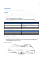
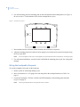
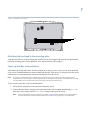
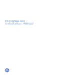
FTP-1000 Touchpad/Display
Installation Manual
A
B
Stay
1
2
3
4
5
6
7
8
9
*
0
#
Away
Disarm
C
Quick
Exit
D
Copyright
Copyright © 2005, GE Security Inc. All rights reserved.
This document may not be copied or otherwise reproduced, in whole or in part, except as
specifically permitted under US and international copyright law, without the prior written
consent from GE.
Document number/revision: 466-2231A (December 2005).
Disclaimer
THE INFORMATION IN THIS DOCUMENT IS SUBJECT TO CHANGE WITHOUT NOTICE. GE ASSUMES
NO RESPONSIBILITY FOR INACCURACIES OR OMISSIONS AND SPECIFICALLY DISCLAIMS ANY
LIABILITIES, LOSSES, OR RISKS, PERSONAL OR OTHERWISE, INCURRED AS A CONSEQUENCE,
DIRECTLY OR INDIRECTLY, OF THE USE OR APPLICATION OF ANY OF THE CONTENTS OF THIS
DOCUMENT. FOR THE LATEST DOCUMENTATION, CONTACT YOUR LOCAL SUPPLIER OR VISIT US
ONLINE AT WWW.GESECURITY.COM.
This publication may contain examples of screen captures and reports used in daily operations.
Examples may include fictitious names of individuals and companies. Any similarity to names
and addresses of actual businesses or persons is entirely coincidental.
Trademarks and patents
GE and the GE monogram are registered trademarks of General Electric.
FTP-1000 touchpad/display product and logo are registered trademarks of GE Security.
Other trade names used in this document may be trademarks or registered trademarks of the
manufacturers or vendors of the respective products.
Intended use
Use this product only for the purpose it was designed for; refer to the data sheet and user
documentation. For the latest product information, contact your local supplier or visit us online
at www.gesecurity.com.
FCC compliance
This equipment has been tested and found to comply with the limits for a Class B digital device,
pursuant to part 15 of the FCC Rules. These limits are designed to provide reasonable
protection against harmful interference when the equipment is operated in a commercial
environment. This equipment generates, uses, and can radiate radio frequency energy and, if
not installed and used in accordance with the instruction manual, may cause harmful
interference to radio communications.
You are cautioned that any changes or modifications not expressly approved by the party
responsible for compliance could void the user's authority to operate the equipment.
1
Preface
This is the GE FTP-1000 Installation Manual for model 600-1020. This document includes an overview of the
product and detailed instructions explaining:
•
•
how to install the touchpad; and
how to program the touchpad.
There is also information describing how to contact technical support if you have questions or concerns.
To use this document effectively, you should have the following minimum qualifications:
•
•
a basic knowledge of security systems and components; and
a basic knowledge of electrical wiring and low-voltage electrical connections.
Read these instructions and all ancillary documentation entirely before installing or operating this product.
The most current versions of this and related documentation may be found on our website. Refer to Online
publication library on page 9 for instructions on accessing our online publication library.
Note:
A qualified service person, complying with all applicable codes, should perform all required hardware installation.
Conventions used in this document
The following conventions are used in this document:
Bold
Menu items and buttons.
Italic
Emphasis of an instruction or point; special terms.
File names, path names, windows, panes, tabs, fields, variables, and other GUI elements.
Titles of books and various documents.
Blue italic
(Electronic version.) Hyperlinks to cross-references, related topics, and URL addresses.
Monospace
Text that displays on the computer screen.
Programming or coding sequences.
Safety terms and symbols
These terms may appear in this manual:
CAUTION:
Cautions identify conditions or practices that may result in damage to the equipment or other property.
WARNING:
Warnings identify conditions or practices that could result in equipment damage or serious personal injury.
2
FTP-1000
Installation Manual
Product overview
The FTP-1000 lets you control the operation of compatible security systems (see Table 4 on page 10).
The large display provides easy to read messages to indicate the current status of the system. The touchpad
includes police, fire, and auxiliary panic buttons that can be activated anytime. A built-in speaker provides
alarm, status, and button-press sounds. A swing-down door reveals a label with basic system operating
commands. The door can be removed by simply opening it past its stop point. The door can also be reattached
later if desired.
Tools and equipment needed
•
•
•
•
•
4-conductor, 22- or 18-gauge wire
Screwdriver
#6 screws and anchors (included)
Panhead screws for gang box installation
Saw or utility knife for cutting wallboard
3
Installation
Use the following instructions to install and wire your touchpad.
Guidelines
•
•
•
•
•
Table 1.
Mount the touchpad in an environmentally controlled area (32 to 120°F or 0 to 49°C).
When mounting the touchpad, allow at least 3 inches below it for the swing-down cover.
Do not exceed the maximum available power. See the panel installation instructions for maximum
available power.
Table 1 describes the power used by the touchpad.
Table 2 describes the maximum wire lengths allowed between the touchpad and the panel.
Touchpad power usage
Current (mA)
Conditions
75
Maximum alarm current with the buzzer sounding and the
touchpad illuminated from a button press
50
Typical operation
12
Power saving mode (no panel AC power)
Table 2.
Maximum touchpad wire lengths
Wire gauge (unshielded or shielded)
Max touchpad wire length between touchpad and panel
18
750 feet
22
300 feet
Mounting plate installation
To install the mounting plate, do the following:
1. Separate the mounting plate from the touchpad by first loosening the screw, then lift the touchpad
away from the mounting plate (see Figure 1).
Figure 1. Mounting plate screw
Mounting plate screw
4
FTP-1000
Installation Manual
2. For wall mounting, place the mounting plate on the wall and mark the mounting holes (see Figure 2).
Be sure to leave a 3-inch clearance below for the touchpad door to open.
Figure 2. Mounting hole locations
3. Insert anchors into the wall at the marked locations where studs are not present.
4. Align the mounting plate holes with the wall or gang box screw holes and secure the back plate using
the screws provided.
Note:
Do not overtighten screws or the mounting plate may bind and prevent the touchpad from mounting properly.
5. For wall-mount installations, cut a hole in the wall behind the mounting plate to pull the wiring cable
through.
Wiring the touchpad to the panel
To wire the touchpad to the panel, do the following:
1. Remove panel AC and backup battery power.
2. Run a 4-conductor, 18- to 22-gauge wire from the panel to the touchpad location (see Table 2 on
page 3).
3. Connect the touchpad +12V, Bus A, Bus B, and GND terminals to the matching panel terminals
(Figure 3 on page 5).
Note:
The wiring should extend from the right side of the connector.
5
Figure 3. Touchpad wiring connections
+12V
Bus A
Bus B
GND
Attaching the touchpad to the mounting plate
Align the tabs at the top of the mounting plate with the slots on the touchpad and swing the touchpad bottom
toward the mounting plate. Gently tighten the screw into the bottom of the touchpad.
Power-up and bus communication
After making all wiring connections from the touchpad to the panel, you are ready to power up the panel and
verify correct communication between the touchpad and the panel. Upon power-up, the panel scans the bus for
connected devices and automatically learns the unit number of each bus device.
Note:
If you plan to install systems with no alphanumeric touchpads, we recommend that you keep an alphanumeric
touchpad with you, specifically for installer programming. This touchpad can be quickly connected and disconnected
from the header pins on the lower-left portion of the panel, just above the terminal strip.
To power up the panel and verify bus communication:
1. Verify that all wiring between the panel and touchpad is correct.
2. Connect the panel battery and plug in the panel transformer. The touchpad should display BUS SCAN,
then show a time display with the PRESS STATUS prompt in the upper-left corner.
Note:
If the touchpad does not power up (show any display) or respond as described above, unplug the panel AC
transformer and disconnect the backup battery. See Troubleshooting on page 9 for more information.
6
FTP-1000
Installation Manual
Testing
Use the following procedures to test the touchpad for display function, button function, and system operation.
Test touchpad display function
Press and hold the 4, 5, and 6 buttons together for about three seconds, then release them.
The touchpad cycles though all text messages, then returns to the time display.
Test button function
To test the button functions, do the following:
1. Press and hold the 7, 8, and 9 buttons together for about three seconds, then release them. The display
should go blank.
2. Press each touchpad button to display a different string of letters or numbers for each button. For
example, 11111111111, AAAAAAAAAAA, etc. Pressing * displays Es and pressing # displays Fs. After
about 15 seconds of no touchpad activity, the touchpad returns to the time display.
Test system operation
Testing the system operation requires you to perform some standard operations to ensure that they work
properly.
CAUTION:
Contact the central monitoring station before activating alarms, to avoid dispatching local police and fire
departments
To test the system’s operation, do the following:
Arm/disarm the system, activate the touchpad panics, bypass sensors, and turn chime on/off to verify correct
operation.
Note:
You must enable the touchpad panic buttons in order to activate them. Please see the panel installation instructions for
more information.
Refer to the panel’s user manual for complete system operating instructions and user programming procedures.
7
Adjusting display brightness
You can adjust the background lighting (provided by yellow LEDs) of each touchpad individually to help
compensate for lighting conditions at the touchpad location. The brightness adjustment lightens or darkens the
display background and button lighting.
Adjust display background brightness
To adjust display background brightness, do the following:
1. Enter user programming mode by pressing 9 + system master code. The display shows SYSTEM MENU,
then TIME - dATE.
2. Press A or B until the display shows OPTIONS, then press #. The display shows dOWnLd ON.
3. Press A or B until the display shows BRIgHT 2 (default setting).
4. Enter a setting from 0 (LEDs off) to 3 (brightest), then press #. The display shows the new setting.
5. Exit user programming by pressing:
•
•
* + 4 + # for Concord Express panels,
or * + 00 + # for Concord panels.
8
FTP-1000
Installation Manual
Changing chime and trouble beep tones
The frequency (pitch) of chime and trouble beep tones from each touchpad can be adjusted to a more desirable
or distinct tone, and to compensate for hearing impaired persons.
Note:
Chime and trouble beep tones sound (using the default frequency) during, or within 15 seconds of any button activity at
that specific touchpad.
Change status tone pitch
To change the status tone pitch, do the following:
1. Press and hold the * and 0 buttons together until you hear a steady tone, then release the buttons.
2. Press and hold 1 to lower the pitch or press and hold 2 to raise the pitch.
3. Release the button when the desired pitch is heard. After about 15 seconds of no touchpad activity, the
steady tone stops sounding.
9
Troubleshooting
The following describes what to do if the touchpad does not operate correctly.
• The touchpad doesn’t power up (no display and no beeps when buttons are pressed).
1. Check for correct wiring connections at touchpad and panel terminals.
2. Make sure that the panel battery is connected correctly and that the panel transformer is plugged in.
3. Make sure panel transformer is not plugged into an electrical outlet controlled by a switch. Relocate
the transformer to an unswitched outlet location, if necessary.
• The touchpad display appears blank, but beeps sound when I press buttons.
Check for correct bus wiring connections (green and white wires) at touchpad and panel terminals.
Contacting technical support
For assistance installing, operating, maintaining, and troubleshooting this product, refer to this document and
any other documentation provided. If you still have questions, you may contact technical support during
normal business hours (Monday through Friday, excluding holidays, between 6 a.m. and 5 p.m. Pacific Time).
Table 3.
Sales and support contact information
Sales
Phone:
Technical support
Toll-free: 888.GESECURity (888.437.3287 in the US, including Alaska and Hawaii; Puerto Rico; Canada).
Outside the toll-free area: 503.885.5700.
E-mail
[email protected]
[email protected]
Fax
800.483.2495
541.752.9096 (available 24 hours a day)
Note:
Be ready at the equipment before calling for technical support.
Online publication library
Another great resource for assistance with your GE Security products is our online publication library,
available to all of our customers on our website. To access our publication library, go to our website at the
following location:
http://www.gesecurity.com
In the Tools area at the top, click the Publication Library link. After you register and log on, you may search
through our online library for the documentation you need.1
1.
Many GE Security documents are provided as PDFs (portable document format). To read these documents, you will need
Adobe Acrobat Reader, which can be downloaded free from Adobe’s website at www.adobe.com.
10
FTP-1000
Installation Manual
Appendix A Specifications and notices
Table 4.
Specifications
Specification
Rating
Compatibility
Concord, Concord Express, Concord Ultra, Concord 4
Power requirements
12 VDC nominal, 75 mA
Temperature range
32 to 120°F (0 to 49°C) Operating
-30 to 140°F (-34 to 60°C) Storage
Maximum humidity
85% relative, noncondensing
Dimensions
5 in. x 4.50 in. x 0.75 in. (L x W x D)
UL/cUL listings
UL (985, 1023, 1610)
cUL (C1023 - 1974, S545 - M89)
For cUL listed applications, the unit shall be installed in accordance with
Part 1 of the Canadian Electrical Code.
Note:
See specific panel installation instructions for complete UL installation requirements for the system you are installing.
Radio interferance information to the user
If this equipment causes harmful interferance to radio or television reception, which can be determined by
turning the equipment off and on, the user is encouraged to try to correct the interferance by one or more of the
following measures:
•
•
•
•
Reorient or relocate the receiving antenna.
Increase the separation between the equipment and receiver.
Connect the affected equipment and the panel receiver to separate outlets, on different branch circuits.
Consult the dealer or an experienced radio/TV technician help.