1
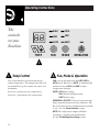
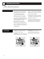
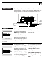
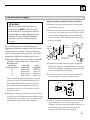
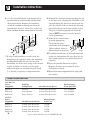
Zoneline Heat Pump Model
5200 Series
Zoneline
®
Owner’s Manual
Important Safety Information
3
Operating Instructions
4
The Controls on Your Zoneline
Care of Product
Installation Instructions
10
Important Electrical Safety
Adjustments and Auxiliary Controls
Helpful Information
20
Things That Are Normal
If Something Goes Wrong
Before You Call For Service
GE Service Numbers
Warranty
GE Answer Center ®
800.626.2000
GE Appliances
49-7367
21
Welcome
Welcome to the GE family. We’re
proud of our quality products and
we believe in dependable service.
You’ll see it in this easy-to-use
manual and you’ll hear it in the
friendly voices of our customer
service department.
Best of all, you’ll experience
these values each time you enjoy
the comfort of your Zoneline.
That’s important, because your
new Zoneline will be part of your
family for a long time.
Start Here!
Staple your receipt to the inside back
cover of this manual. You will need it
to obtain service under warranty.
Write down the model and serial
numbers here. They are on a label
behind the room cabinet on the
base pan.
Before using
your
Zoneline
Model number
Serial number
Date of purchase
Need Help?
Help us
help you
800.626.2000
2
Before you call for service,
there are a few things you can
do to help us serve you better.
Read this manual. It contains
instructions to help you use and
maintain your Zoneline properly.
Save time and money. Check the
section titled If Something Goes
Wrong before calling. This section
was designed to solve common
problems that might occur.
If you do need service, you can
relax knowing help is only a phone
call away. Toll-free customer service
numbers are included in the back
of this manual. Or call the GE
Answer Center® at 800.626.2000,
24 hours a day, 7 days a week.
IMPORTANT SAFETY INFORMATION
READ ALL SAFETY INFORMATION
BEFORE USING
• This Zoneline must be properly
installed in accordance with the
Installation Instructions before it
is used.
• Repair or replace immediately
all electric service cords that have
become frayed or otherwise
damaged.
• Unplug or disconnect the
Zoneline at the fuse box or
circuit breaker before making
any repairs.
NOTE: We strongly recommend
that any servicing be performed
by a qualified individual.
SAVE THESE INSTRUCTIONS
Replacing an
existing unit?
For details see the Installation
Instructions in the back of this
manual.
3
Operating Instructions
The
controls
on your
Zoneline
HIGH
COOL
LOW
FAN
AUTO
HEAT
ON
STOP
TEMP
FAN
1
1
Temp Control
MODE
OPERATION
2
2
Fan, Mode & Operation
The temp control is used to maintain the
room temperature. The compressor will cycle
on and off to keep the room at the same level
of comfort.
FAN—sets the fan operation for HIGH, LOW or
AUTO speed. When set at AUTO, it automatically
switches between LOW and HIGH as room
temperature changes.
Press the + pad to raise the temperature.
MODE—COOL—For cooling
FAN—For fan-only operation
HEAT—For heating
Press the – pad to lower the temperature.
OPERATION—ON/STOP—Turns the unit on or off.
Power remains connected to the Zoneline. The
Freeze Sentinel feature still functions if switch E
is “on.” See the Freeze Sentinel section.
NOTE: The temperature display will flash
to indicate a possible unit malfunction.
See the If Something Goes Wrong section.
4
Energy Tips
Keep the vent control at CLOSE. The room air will be
filtered and circulated.
Set the FAN at AUTO. It switches between LOW and
HIGH to adjust for room temperature changes.
Louver screws
Louver screws
Remove the room cabinet and
flip the louvers to change the air direction.
Vent
control
OPEN
CLOS
E
3
3
Ventilation Control
The ventilation control lever is located at the
lower left side of the Zoneline unit, behind the
room cabinet.
When set at CLOSE, only the air inside the room
is circulated and filtered.
4
4
Air Direction
To adjust the air direction, remove the room
cabinet. Remove the 7 louver screws that
hold the louvers in place. Flip the louver
section 180°, replace the screws and the
room cabinet.
When set at OPEN, some outdoor air will be
drawn into the room. This will reduce the
heating or cooling efficiency.
5
Operating Instructions
Other Zoneline features
About Your Heat Pump
Heat pumps can save money by
removing heat from the outside
air—even when the outside
temperature is below freezing—
and releasing that heat indoors.
To get the best performance from
your heat pump, don’t change the
room thermostat very often.
Raising the heat setting 2–3
degrees will cause the Zoneline to
use its electric heating elements in
order to reach the new temperature
setting quickly.
To Remove the
Room Cabinet
Additional controls are located
behind the room cabinet.
To remove: Pull out at the bottom to
release it from the tabs. Then lift up.
The indoor fan motor starts before
the compressor and stops after the
compressor cycles off.
The electric heating elements use
much more electricity than heat
pumps and cost more to operate.
To replace: Place the tabs over
the top rail. Push inward at the
bottom until it snaps into place.
1
2
1
6
There is a three minute minimum
compressor run time at any setting
to prevent short cycling.
2
Auxiliary Controls
The auxiliary controls are located behind the room cabinet on the front of
the unit control box. The factory settings will be in the DOWN position. The
owner is responsible for checking switches and ensuring they are in the
desired position.
1 2 3 4 5 6 7 8 9 A BC D E
UP
Temp Limit Cool
Temp Limit Heat
All Electric Heat
Boost
UP: Cycle fan
DOWN: Continuous fan
Fan Switch
The fan switch #9 is located behind
the room cabinet.
1 2 34 5 6 7 8 9A BCDE
UP
DOWN
Auxiliary Controls
This switch is set at continuous fan
(DOWN) at the factory to provide
continuous fan operation in cool
or heat modes. Leaving the switch
in the continuous fan setting allows
continuous circulation of room air
and will result in a more balanced
temperature throughout the room.
DOWN
Freeze
Sentinel
Self
Diagnostics
CDC (Load
Shedding)
All Time Low Fan
Remote Control (Class 2)
If you want the fan to cycle on
and off with the compressor or
with the heater, move the switch
to cycle fan (UP).
Down—Continuous Fan
Up—Cycle Fan
Freeze Sentinel ™
1 2 34 5 6 7 8 9A BCDE
UP
DOWN
Auxiliary Controls
Switch E controls the Freeze
Sentinel. When the switch is DOWN
the Freeze Sentinel automatically
turns on the resistance heater and
fan if the room temperature (sensed
at the unit) drops to approximately
40° F. It will turn the heater off when
the temperature reaches about 45° F.
The unit leaves the factory with the
Freeze Sentinel in the DOWN (on)
position.
The Freeze Sentinel helps prevent
plumbing damage in the room due
to sub-freezing temperatures.
If the Freeze Sentinel is set, it is
active as long as power to the
unit is on.
NOTE: The owner is responsible for
checking the Freeze Sentinel switch
and ensuring it is in the desired
7
setting.
Operating Instructions
Care & Cleaning
Room Cabinet
and Case
Outdoor Coils
Base Pan
Turn the Zoneline off and
disconnect the power supply.
The coils on the outdoor side of
the Zoneline should be checked
regularly. If they are clogged with
dirt or soot they may be
professionally steam cleaned, a
service available through your
GE service outlet. You will need to
remove the chassis to inspect the
coils because the dirt build-up
occurs on the inside.
In some installations, dirt or other
debris may be blown into the unit
from the outside and settle in the
base pan (the bottom of the unit).
In some areas of the United States
a “gel-like” substance may be seen
in the base pan.
8
To clean, use water and a mild
detergent. Do not use bleach or
abrasives. Some commercial
cleaners may damage the plastic
parts.
Grille
Coils
Clean the outside coils
regularly.
Check it periodically and clean it
out, if necessary.
Air Filters
Operating Tip:
To maintain optimum
performance, clean
the filters at least
every 30 days.
FRONT
Turn the Zoneline off before cleaning.
The most important thing you can
do to maintain the Zoneline is to
clean the filter at least every 30
days. Clogged filters reduce
cooling, heating and air flow.
To remove the air filters:
2 air filters
Pull
up
Keeping these filters clean will:
• Decrease cost of operation.
• Save energy.
• Prevent clogged heat exchanger
coils.
To replace the air filters:
• Reduce the risk of premature
component failure.
Dirty filter—Needs cleaning
FRONT
Clogged filter—Greatly
reduces cooling, heating
and airflow.
To clean the air filters:
• Vacuum off the heavy soil.
• Run water through the filters.
• Dry thoroughly before replacing.
Push
down
CAUTION:
DO NOT operate the Zoneline without
the filters in place. If a filter becomes
torn or damaged it should be
replaced immediately.
Operating without the filters in
place or with damaged filters will
allow dirt and dust to reach the indoor coil and reduce the cooling,
heating, airflow and efficiency of
the unit.
Replacement filters are available
from your salesperson, GE dealer,
GE Service and Parts Center
or authorized Customer Care®
servicers.
9
Installation Instructions
Read carefully
If you have any questions, call the GE Answer Center at 800.626.2000.
Replacing an Existing Unit?
Check the “Essential
Elements” label for
important information.
• Any vertical deflectors in the existing rear grille
should be removed to decrease condenser air
recirculation which can cause the unit to
“short-cycle” and lead to premature component failure.
• Replacing a ducted chassis.
• Use the correct wall case.
This chassis is designed to be installed in a GE
plastic or insulated metal wall case. This minimizes condensation from forming on the room
side of the case. If the current wall case is not
insulated, you can reduce the possibility of
condensation forming by installing insulation
kit RAK901L, available where you purchased
the chassis.
• Use the correct outdoor grille.
You should use the outdoor grilles shown on
the “Essential Elements” label on the top of
the chassis.
• If an existing grille is not replaced, capacity and
efficiency will be reduced and the unit may fail
to operate properly or fail prematurely. A
deflector kit, RAK40, may be used with grilles
that were not designed for your new GE
Zonelines. The RAK40 contains air deflectors
and gaskets that mount to the chassis to direct
the hot exhaust air away from the air intake to
allow the unit to function properly. The grille
must have a 65% minimum free area.
10
New ducted installation—If this unit is to be
installed in a new ducted application using a
duct adaptor kit, the kit must be installed before
the chassis is placed in the wall case. The installation instructions are packed with the kit.
Mounting
plate
Duct
Case
Existing ducted installation—Replacement of an
existing ducted unit may require different components. Request this information from your
sales representative.
• Replacing 230/208 volt units.
See page 12.
• Replacing 265 volt units.
See page 13.
Important Electrical Safety—Read Carefully
Installer: Leave these instructions with the Zoneline.
Owner: Keep these instructions for future use.
Important Notes
• Follow the National Electrical Code (NEC) or
local codes and ordinances.
• For personal safety, this Zoneline must be properly grounded.
• Protective devices (fuses or circuit breakers)
acceptable for Zoneline installations are specified on the nameplate of each unit.
CAUTION:
• Do not use an extension cord with this unit.
• Aluminum building wiring may present special
problems—consult a qualified electrician.
• When the unit is in the STOP position there is still
voltage to the electrical controls.
• Disconnect the power to the unit before servicing
by:
1 Removing the power cord (if it has one) from the
wall receptacle.
or—
2 Removing the branch circuit fuses or turning the
circuit breakers off at the panel.
Zoneline Components
YOU WILL NEED:
Exterior grille/louver**
• Universal power connector kit
• Phillips screwdriver
Wall case**
Zoneline unit
Room cabinet*
Power supply kit**
*Shipped with the Zoneline unit
**Check the “Essential Elements” list on the unit
11
Installation Instructions
How to Connect
1 Remove the room cabinet.
2 Install the power supply kit per the
instructions in the kit.
3 See the special instructions below for
applicable supply voltages.
4 Reinstall the room cabinet.
230/208 Volt Electrical Supply
A power supply kit must be used to supply
power to the Zoneline unit. The appropriate
kit is determined by the voltage, the means of
electrical connection and the amperage of the
branch circuit.
Connections of 208 or 230 volt circuits may be
with a power supply kit or a junction box kit.
All wiring, including installation of the
receptacle, must be in accordance with the NEC
and local codes, ordinances and regulations.
Tandem
Perpendicular Large Tandem
15 Amp.
20 Amp.
30 Amp.
Electrical wiring wall outlets 230/208 volts.
12
Power supply kit
265 Volt Electrical Supply
Steps for preparing cordset for direct connection:
WARNING
Connection of this 265V product to a
branch circuit MUST be done by direct
connection to be in compliance with the
National Electric Code. Plugging of this
unit directly into a building mounted
exposed receptacle is not permitted
by code.
These models must be installed using the
appropriate GE power supply kit for the branch
circuit amperage and the electrical resistance
heater wattage desired. See page 14. One of the
following installation methods must be used:
A Electrical subbase kits are available to provide
a flexible enclosure for direct connection.
Branch Circuit
and Chassis
Amperage Rating
15
15
20
30
Proper GE
Subbase Kit
RAK204E15
RAK204E15
RAK204E20
RAK204E30
Power
Supply Kit
RAK5152
RAK5172
RAK5202
RAK5302
The instructions provided with the selected
subbase kit must be carefully followed. It is
the responsibility of the installer to ensure
that connection of components is done in
accordance with these instructions and all
electrical codes.
B For direct connection to branch circuit wiring
inside the provided junction box without using
a subbase kit, the cord is to be cut and the wire
ends stripped and connected as follows.
1 Remove the junction box cover by taking out
the front four screws.
2 Remove the junction box by taking out the top
rear screw. Note how the slot at the lower right
corner of the junction box serves to hold the
corner in place. This will help when the box is
being reinstalled.
Tab on
chassis
Chassis
connector
Junction
box cover
Junction box
Slot in
junction box
3 Remove the cordset from the power supply kit.
Measure 4″ down the cord from where it emerges
from the back of the nylon plastic connector and
cut the cord through at this point.
4 Carefully remove 3″ of the cordset insulation
so as to expose the three insulated wires.
3/4″
Connector
3″
4″
5 Strip 3/4″ of the insulation away at the end of
each of the three wires (L1, Neutral and
Ground). Plug the connector fully into place in
the chassis mating connector. Be sure the
locking tabs at the sides are engaged.
13
Installation Instructions
6 Use the round knockout at the bottom of the
junction box to attach conduit coming from
the branch circuit. Remove the knockout,
attach the conduit and bring wires into the
junction box. Leave 6″ of wire free at the end
of the conduit to allow connections to be made.
8 Reinstall the junction box by engaging the tab
at the lower rear, aligning the screw hole at the
top and driving the one screw until secure. Be
sure that all wire leads are inside the box and
not pinched between the box and the chassis.
The green insulated ground wire from the
chassis MUST be connected to the branch
circuit ground wire.
9 Make all wire connections
by using appropriate
UL-listed electrical
connectors and techniques
(black to black, white to
white and green to green).
Conduit
7 If a fuse and fuseholder are to be used, the
knockout at the top of the box is for mounting
of a Buss Fuseholder. Be sure the fuse and
fuseholder are of the same rating as the branch
circuit. Leadwires at the fuse can be either
soldered in place or attached using UL-listed,
1/4″ female (receptacle) crimp connectors.
10 Carefully tuck all wires and connections back
inside the junction box. Be sure there are no
loose connections or stray uninsulated wires
exposed.
11 Place the junction box cover in place.
Replace the four screws removed earlier
and tighten securely.
12 Discard the unused portion of the plug and
the cordset.
Power Connection Chart
230/208 Volt
Power
Supply Kits
Wall Plug
Configuration
Circuit Protective Device
Heater Wattage
@ 230/208 Volts
RAK3152
RAK3202
RAK3302*
Tandem
Perpendicular
Large Tandem
15 Amp Time Delay fuse
20 Amp Time Delay fuse
30 Amp Time Delay fuse
2.55/2.09 KW
3.45/2.82 KW
5.00/4.10 KW
265 Volt
Power
Supply Kits
Circuit Protective Device
Heater Wattage
@ 265 Volts
RAK5152
RAK5172
RAK5202
RAK5302*
15 Amp Time Delay fuse
15 Amp Time Delay fuse
20 Amp Time Delay fuse
30 Amp Time Delay fuse
1.7 KW
3.0 KW
3.7 KW
5.0 KW
14
Conduit
*Not recommended for use on 7000 BTUH units.
1
Install the Wall Case and the Exterior Grille
1 The RAB71 or RAB77 wall case must be
properly installed per instructions packed
with the case.
2 Remove the corrugated stiffener and the
outdoor protective panel. Use the slit in the
outdoor panel as a handhold and push out.
Protective
panel
Slit
Insulated Wall Case
This chassis is designed to be installed in a
GE plastic or an insulated steel wall case. This
minimizes condensation from forming on the
room side of the case.
The RAB71 wall case is insulated. Insulation kit
RAK901L is available for use with RAB77 or
existing uninsulated wall cases when needed.
NOTE: For installation with a subbase or duct
adaptor, see the instructions packed with those kits.
Stiffener
3 Install the exterior grille from the room side
following instructions packed with the grille.
2
Remove the Shipping Tape from the Room Cabinet
1 Carefully remove shipping tape, if there is any,
from the room cabinet and vent door.
2 Remove the room cabinet by pulling it out at
the bottom to release it, then lift it up to clear
the rail along the unit top.
2
Shipping tape
1
15
Installation Instructions
3
Install the Unit into the Wall Case
Slide the unit into the wall case and secure with
four screws through the unit flange holes.
If an insulated wall case is needed, see Install the
Wall Case and Exterior Grille section on the
previous page.
4
Replace the Room Cabinet
Reinstall the room cabinet by hooking the top
over the rail along the unit top, then pushing it in
at the bottom.
1
2
16
Low Voltage Connectors & Auxiliary Controls
Boost Heat Option
The Boost Heat Option increases the Zoneline
air temperature by adding electric heat to
supplement the heat pump. It automatically
turns on when the outside temperature is
between 25° F and 45° F.
To set the Boost Heat Option, move switch #8 to
the UP (on) position.
If the Zoneline is controlled by a wall thermostat
and Boost switch #8 is set to the UP (on)
position, only electric heat is available when the
outdoor temperature is below 45° F.
The Boost Heat Option is more expensive than
heating with the heat pump only.
1 2 34 5 6 7 8 9A BCDE
UP
DOWN
Auxiliary controls
Electric Heat Option
The Electric Heat Option increases the Zoneline
air temperature by using electric heat only. The
heat pump is not used to produce any heat.
If you want warmer air from the Zoneline and
the Boost Heat Option is not warm enough,
this option will provide the hottest air available.
To set the Electric Heat Option, move switch #7
to the UP (on) position.
1 2 34 5 6 7 8 9A BCDE
UP
DOWN
Auxiliary controls
Using the Electric Heat Option is much more
expensive than heating with the heat pump only.
17
Installation Instructions
Remote Control/Wall Thermostat (Class 2)
To operate the Remote Control/Wall
Thermostat (Class 2) switch A, you must use
an Optional Interface Module kit. See the
Installation Instructions with accessory kit
RAK0IM.
1 2 34 5 6 7 8 9A BCDE
UP
DOWN
Auxiliary Controls
Central Desk Control (Load Shedding)
To operate Central Desk Control (CDC),
switch C, you must have an Optional Interface
Module kit. See the Installation Instructions with
accessory kit RAK0IM.
1 2 34 5 6 7 8 9A BCDE
UP
DOWN
All-Time Low Fan
Switch B controls the All-Time Low Fan and is
only effective with a Remote Control Thermostat.
This function causes the indoor fan to operate at
low speed. If the switch is DOWN (off) the fan will
run in high speed. If the switch is UP (on) the fan
will run in low speed.
18
1 2 34 5 6 7 8 9A BCDE
UP
DOWN
Temperature Limiting
Temperature limiting can reduce energy costs
by limiting the lowest temperature that can be
set for cooling and the highest temperature that
can be set for heating. Temperature limiting is
controlled by setting the first six auxiliary
switches.
The first three are used to select cooling range
limits and the next three are used to select
heating range limits.
1 2 34 5 6 7 8 9A BCDE
UP
DOWN
Auxiliary controls
COOLING LIMITS
Limit Switch
UP/On
Temp Range
F.
None
1
1&2
2
2&3
1&2&3
1&3
3
60 to 85
64 to 85
66 to 85
68 to 85
70 to 85
72 to 85
74 to 85
76 to 85
HEATING LIMITS
Limit Switch
UP/On
Temp Range
F.
None
4
4&5
5
5&6
4&5&6
4&6
6
60 to 85
60 to 80
60 to 78
60 to 76
60 to 74
60 to 72
60 to 70
60 to 65
Diagnosis Switch
The Zoneline has a diagnosis feature. When
switch D is moved to the UP (on) position, the
unit will go through an operations check of all
components which takes about two minutes.
This diagnostic tool is intended for use by a
qualified technician.
1 2 34 5 6 7 8 9A BCDE
UP
DOWN
Auxiliary controls
19
Helpful Information
Things That Are Normal
Noise
Explanation
P I N G!
POP!
“CLICK”
DRIP
WHIR!
te
u
n
i
3-MDelay
SILENCE
COMPRESSOR
PROTECT
20
You may hear a pinging or popping noise caused by water being
picked up and thrown against the condenser on rainy days or
when the humidity is high. This design feature helps remove
moisture and improve efficiency.
You may hear relays click when the controls cycle on and off or are
adjusted to change the room temperature.
Water will collect in the base pan during high humidity or on rainy
days. The water may overflow and drip from the outdoor side
of the unit.
The indoor fan runs continuously when the unit is operating in the
cooling mode, unless the fan switch behind the room cabinet is set
at fan cycle (up). This will cause the fan to cycle on and off with the
compressor. You may also hear a fan noise stop and start.
You may notice a few minutes delay in starting if you try to restart the
Zoneline too soon after turning it off or if you adjust the thermostat
right after the compressor has shut off. This is due to a built-in
restart protector for the compressor that causes a 3-minute delay.
The compressor shuts off during the defrost cycle. Full resistance
heat comes on during the defrost cycle to maintain room comfort.
To protect the compressor and prevent short cycling, the unit is
designed to run for a minimum of 3 minutes, after the compressor
starts at any thermostat setting.
If Something Goes Wrong
Before You Call For Service
Problem
Possible Causes
What to Do
Zoneline
Doesn’t Start
The unit is unplugged
• Make sure the Zoneline plug is
pushed completely into the outlet.
The fuse is blown/circuit
breaker is tripped
• Check the house fuse/circuit breaker
box and replace fuse or reset the breaker.
The unit is waiting for the
compressor overload
protector to reset
• This is normal. The Zoneline will start
again after it resets.
Power failure
• If power failure occurs, set the mode
control to STOP. When power is restored
set the mode control to the desired setting.
There is a protective time delay (up to
3 minutes) to prevent tripping of the
compressor overload. For this reason, the
unit may not start normal heating or
cooling for 3 minutes after it is turned
back on.
Zoneline Does Not
Cool or Heat as it
Should
Indoor airflow
is restricted
• Make sure there are no curtains, blinds
or furniture blocking the front of the
Zoneline.
Outdoor airflow
is restricted or
recirculated
• Make sure the rear grille is not restricted.
This can cause the unit to cycle off due to
the compressor overload.
The temp control may
not be set high or low
enough
• Turn the control to a lower or higher
setting. NOTE: The temperature limiter may
be limiting the temperature range.
The air filter is dirty
• Clean the filter at least every 30 days.
The room may have been
hot or cold
• When the Zoneline is first turned on
you need to allow time for the room to
cool down or warm up.
Outdoor air is
entering the room
• Set the vent control to the CLOSE position.
21
If Something Goes Wrong
Before You Call For Service
Problem
Possible Causes
What to Do
Burning Odor at the
Start of Heating
Operation
Dust is on the surface of
the heating element
• This can cause a “burning” odor at the
beginning of the heating operation. This
odor should quickly fade.
The compressor
may have failed
• Move the control to STOP and then
restart the unit. If the light reappears
within 30 minutes, call for service.
The heat pump is not
producing hot air
• This is normal. The heat pump will
produce warm air but not as hot as air
produced when the higher-cost electric
heat is used.
The fan switch may be set
at continuous fan (down)
• This causes the fan to blow room
temperature air even when the
compressor or heater cycles off.
The continuous air movement provides
better overall temperature control.
The heat pump alone
produces air that feels
cooler than desired
• Use the Boost Heat Option to warm the
air. This adds electric heat to the heat
pump when the outside temperature is
between 25°F. and 45°F.
Temperature Display
Flashes
The Air is Not Always
Cool or Hot During
Operation
The Air Does Not Feel
Warm Enough During
Heating Operation
• Use the Electric Heat Option. This turns
off the heat pump and warms with
electric heat only.
NOTE: Use of either of the above options
will result in increased energy
consumption.
22
GE Service Numbers
We’ll be there!
GE Answer Center®
800.626.2000
Open 24 hours a day,
7 days a week.
TDD
800-833-4322
On-Site Repair Service
800-GE-CARES
(800-432-2737)
Parts and Accessories
800-626-2002
We provide expert repair service,
scheduled at a time that’s
convenient for you.
Our factory-trained technicians
know your air conditioner inside and
out—so most repairs can be handled
in just one visit.
Individuals qualified to service
their own air conditioner can have
parts or accessories sent directly
to their home.
Care and cleaning instructions contained in this manual cover procedures to be performed by any user.
Other servicing generally should be
referred to qualified service personnel. Caution must be exercised,
since improper servicing may cause
unsafe operation.
VISA, MasterCard and Discover
cards are accepted.
Further Service
If for some reason you
are not happy with the
service you receive, here
are three steps to follow
for further help.
First, contact the people who serviced your air conditioner. Explain
why you are not pleased.
Next, if you are still not pleased,
write all the details—including
your phone number—to:
Consumer Relations
GE Appliances,
Louisville, KY 40225
Finally, if your problem is still
not resolved, write:
Major Appliance
Consumer Action Program
20 North Wacker Drive
Chicago, IL 60606
23
ZONELINE
WARRANTY
Staple sales slip or cancelled check here.
Proof of original purchase date is needed
to obtain service under warranty.
All warranty service will be provided
by our Factory Service Centers, or an
authorized Customer Care® technician.
For service in the U.S., call
800-GE-CARES.
For service in Canada, call
1-800-361-3400.
What Is Covered
FULL ONE-YEAR WARRANTY
For one year from date of original purchase, we will provide, free of charge,
parts and service labor on site to repair
or replace any part of the Zoneline that
fails because of a manufacturing defect.
FULL FIVE-YEAR WARRANTY
For five years from the date of original
purchase, we will provide, free of
charge, parts and on-site service labor
to repair or replace any part of the sealed
refrigerating system (the compressor, condenser, evaporator and all connecting
tubing) that fails because of a manufacturing defect.
LIMITED 2ND THROUGH
5TH YEAR PARTS WARRANTY
For the second through the fifth year
from date of original purchase, General
Electric will provide, free of charge,
parts that fail as a result of a manufacturing defect. Parts covered are fan
motors, switches, thermostat, heater,
heater protectors, compressor overload, solenoids, circuit boards, auxiliary
controls, thermistors, Freeze Sentinel,
frost controls, ICR pump, capacitors,
varistors, and indoor blower bearing.
This is a limited parts-only warranty,
and does not include labor or transportation to and from the service shop.
What Is Not
Covered
• Service trips to your site to teach you
how to use the product.
• Improper installation.
If you have an installation problem,
or if the air conditioner is of
improper cooling capacity for the
intended use, contact your dealer
or installer. You are responsible for
providing adequate electrical
connecting facilities.
• Replacement of fuses or resetting of
circuit breakers.
• In commercial locations, labor necessary to move the unit to a location
where it is accessible for service by an
individual technician.
• Failure of the product resulting from
modifications to the product or due
to unreasonable use including failure
to provide reasonable and necessary
maintenance.
• Failure or damage resulting from
corrosion due to installation in an
environment containing corrosive
chemicals.
• Failure or damage resulting from
corrosion due to installation in a
coastal environment, except for
models treated with special factoryapplied anti-corrosion protection as
designated in the model number.
• Damage to product caused by
improper power supply voltage, accident, fire, floods or acts of God.
• Incidental or consequential damage
to personal property caused by possible defects with this air conditioner.
Warrantor: General Electric Company. Louisville, KY 40225
This warranty is extended to the original purchaser and any succeeding owner for products purchased for use
within the USA and Canada. In Alaska, the warranty excludes the cost of shipping or service calls to your site.
Some states do not allow the exclusion or limitation of incidental or consequential damages. This warranty gives you
specific legal rights, and you may also have other rights which vary from state to state. To know what your legal
rights are in your state, consult your local or state consumer affairs office or your state’s Attorney General.
Pub. No. 49-7367
12-97
CG
Printed in China
Zoneline
5200 Series