1
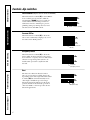
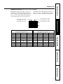
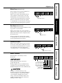
®
Zoneline Vertical
Air Conditioners
GEAppliances.com
Safety Instructions . . . . . . . . . . .2
Operating Instructions
Controls—Dip Switches . . . . . .3–5
Controls—Terminal
Connections . . . . . . . . . . . . . .6, 7
On/Off Switch . . . . . . . . . . . . . . .8
Ventilation Control . . . . . . . . . . .8
Owner’s Manual and
Installation Instructions
Heat/Cool and
Heat Pump Models
7500 Series
Care and Cleaning
Air Filters . . . . . . . . . . . . . . . . . . .9
Base Pan . . . . . . . . . . . . . . . . . . .9
Exhaust Coils . . . . . . . . . . . . . . . .9
Installation Instructions
Electrical Supply . . . . . . . . .11–13
Installing the Zoneline . . . .14–21
Preparation . . . . . . . . . . . . . . . .10
Servicing . . . . . . . . . . . . . . . . . .22
Troubleshooting Tips . . . . . . .23
Normal Operating Sounds . . . .24
Consumer Support
Consumer Support . . .Back Cover
Product Registration . . . . . .25, 26
Warranty . . . . . . . . . . . . . . . . . .27
Write the model and serial
numbers here:
Model # __________________
Serial #____________________
Find these numbers on a label
on the front case panel.
49-7419-2
04-02 JR
Safety Instructions
IMPORTANT SAFETY INFORMATION.
READ ALL INSTRUCTIONS BEFORE USING.
WARNING!
For your safety, the information in this manual must be followed to minimize the risk of fire, electric
shock, or to prevent property damage, personal injury, or loss of life.
SAFETY PRECAUTIONS
Operating Instructions
■ This Zoneline must be properly
installed in accordance with the
Installation Instructions before it is
used. See the Installation Instructions
in the back of this manual.
■ Immediately repair or replace all
electric service cords that have become
frayed or otherwise damaged.
■ Unplug or disconnect the Zoneline at
the fuse box or circuit breaker before
making any repairs.
Care and Cleaning
NOTE: We strongly recommend that any
servicing be performed by a qualified
individual.
Customer Service
Troubleshooting Tips
READ AND FOLLOW THIS SAFETY INFORMATION CAREFULLY.
SAVE THESE INSTRUCTIONS
2
GEAppliances.com
Controls–Dip Switches
The dip switch controls are located behind the
front case panel, through an opening on the
front of the unit.
Dip
Switches
The factory settings will be in the DOWN position.
Side
shipping
screw
NOTE: The owner is responsible for setting
the appropriate dip switches and connecting
terminals.
Operating Instructions
To access the dip switches, remove the front
case panel by removing the filter, taking out the
four front screws, the upper two screws from the
top of the panel and the shipping screws on each
side, if present. (Discard the two side shipping
screws, if present).
Safety Instructions
Controls–dip switches.
Side
shipping
screw
TL1 (H) (Temp. Limit 1–Heat)
TL2 (H) (Temp. Limit 2–Heat)
TL3 (H) (Temp. Limit 3–Heat)
Troubleshooting Tips
ALL I 2R (All Electric Heat) (Heat-pump models only)
FREEZ S (Freeze Sentinel)
CONST FAN (Constant ON Fan)
Care and Cleaning
TL1 (C) (Temp. Limit 1–Cool)
TL2 (C) (Temp. Limit 2–Cool)
TL3 (C) (Temp. Limit 3–Cool)
No Function (Reserved for future use)
DUCT (Blower Fan)
OCCUPIED (Occupancy Sensor)
All Electric Heat (Heat pump models only)
When this switch is enabled (UP), heat pump
operation is locked out, causing the unit to
provide only electric resistance heat.
Customer Service
ALL I2R (All Electric Heat)
3
Freeze Sentinel (Requires room air sensor kit–RAVRMS)
When this switch is enabled (UP), it turns OFF the
freeze sentinel protection feature. With the
switch disabled (DOWN), the freeze sentinel is
activated which automatically provides heat
without user interface. This helps to prevent
plumbing damage by turning the heater and
fans ON at 41° F and OFF at 46° F.
Operating Instructions
Safety Instructions
Controls–dip switches.
FREEZE S (Freeze Sentinel)
Constant ON Fan
When this switch is enabled (UP), it allows the
fans to run continuously, at high speed, even if
the unit is in the STOP position.
CONST FAN (Constant
ON Fan)
Care and Cleaning
Occupancy Sensor
When this switch is enabled (UP), it allows the
unit to utilize an infrared motion sensor and a
door switch for occupancy detection. This feature
allows an energy management system to be
installed and operated in conjunction with
the unit.
OCCUPIED
(Occupancy Sensor)
Duct
Consumer Support
Troubleshooting Tips
The duct select function allows the indoor
fan to be operated at two variable fan speeds,
depending on the duct length. When this switch
is enabled (UP), the unit automatically selects
either high or middle fan speed for longer
ductwork applications. When set in the down
position, the unit is automatically operated in
either the middle or low fan speed for shorter
ductwork applications.
4
DUCT
(Blower Fan)
Temperature Limiting (Requires room air sensor kit–RAVRMS)
Temperature limiting can reduce energy costs
by limiting the lowest temperature that can be
set for cooling and the highest temperature that
can be set for heating. Temperature limiting is
controlled by switches 1–6 on the top block
Temperature limiting during HEAT mode
(all temperatures shown in °F)
UP
DOWN
Minimum Maximum
NONE
4, 5, 6
60°
85°
4
5, 6
60°
80°
4, 5
6
60°
78°
5
4, 6
60°
76°
5,6
4
60°
74°
4, 5, 6
NONE
60°
72°
4, 6
5
60°
70°
6
4, 5
60°
65°
Care and Cleaning
Temperature limiting during COOL mode
(all temperatures shown in °F)
UP
DOWN
Minimum Maximum
NONE
1, 2, 3
60°
85°
1
2, 3
64°
85°
1, 2
3
66°
85°
2
1, 3
68°
85°
2,3
1
70°
85°
1, 2, 3
NONE
72°
85°
1, 3
2
74°
85°
3
1, 2
76°
85°
TL1 (H) (Temp. Limit 1–Heat)
TL2 (H) (Temp. Limit 2–Heat)
TL3 (H) (Temp. Limit 3–Heat)
Operating Instructions
TL1 (C) (Temp. Limit 1–Cool)
TL2 (C) (Temp. Limit 2–Cool)
TL3 (C) (Temp. Limit 3–Cool)
of auxiliary controls. The first three switches are
used to select the cooling limits. The next three
switches are used to control the heating limits.
Safety Instructions
GEAppliances.com
Troubleshooting Tips
Consumer Support
5
Controls–Terminal Connections
The terminal connections are located behind the
front case panel through an opening on the
front of the unit.
To access the terminal connections, remove the
front panel by removing the filter, taking out the
four front screws, the upper two screws from the
top of the panel and the shipping screws on each
side, if present. (Discard the two side shipping
screws, if present).
Operating Instructions
Safety Instructions
Controls—terminal connections.
Terminal
connections
Insert the building hook-up wires into the
bottom of the terminals and tighten screws
securely to make the desired connections.
Route the wires from the terminal connections
through the unit wire guides and out through
the case wire guide.
NOTE: The owner is responsible for setting
the appropriate dip switches and connecting
terminals.
Care and Cleaning
CAUTION:
Troubleshooting Tips
Improper CDC wiring may damage the Zoneline
electronics or cause erratic Zoneline operation.
No common busing is permitted. A separate wire
pair must be run from each separate controlling
switch to each individual Zoneline.
Route wires
through wire
guides
Common–Ground
White–Heater
Yellow–Compressor
Black–Reversing Valve
Green–High Speed Fan
Green–Low Speed Fan
Red–24V AC only
Room Air Sensor
Motion Sensor
Door Sensor
Central Desk Control
Room Air Sensor (Requires room air sensor kit – RAVRMS)
Consumer Support
When connected, the room air sensor will allow
utilization of the temperature limiting and freeze
sentinel features.
NOTE: If GE thermostat RAK147P2 or RAK163P2
is used with the unit, the room sensor kit is not
needed, since temperature limiting and freeze
sentinel features are incorporated in the
thermostats.
6
Room Air
Sensor
Motion Sensor (Obtained locally)
The Occupancy Sensor dip switch must be in
the up position to use this feature.
When connected, the wall mounted motion
sensor will detect motion in the room and
automatically cycle the unit between normal
operation and energy management operation.
Motion Sensor
Operating Instructions
The door and motion sensors work together
to automatically cycle the unit between normal
operation and energy management operation.
Door Sensor (Obtained locally)
The Occupancy Sensor dip switch must be in the
up position to use this feature.
When connected, the door sensor will detect
when the door in the room is opened or closed.
This feature must be used in conjunction with
the motion sensor.
Safety Instructions
GEAppliances.com
Door Sensor
Care and Cleaning
The door and motion sensors work together
to automatically cycle the unit between normal
and energy management operations.
Central Desk Control
When connected, the unit lock-out is released
and it can be turned ON or OFF with a switch
located at the Central Desk Control. A separate
wire pair must be run from each separate
controlling switch to each individual Zoneline.
Central Desk Control
Troubleshooting Tips
Remote Thermostat
The unit will be controlled by a remote
thermostat.
IMPORTANT:
The Zoneline thermostat connections
provide 24V AC only.
CAUTION:
Damage to a wall thermostat or to the
Zoneline electronics can result from improper
connections. Exercise extra attention when
connecting blue and black wires. No line
voltage connections should be made to any
circuit in the thermostat. Isolate all wires in
building from line voltage.
Consumer Support
If using a digital/electronic wall thermostat,
you must set it to the 24V AC setting. See the
Installation Instructions for the wall thermostat.
Red–24V AC only
Green–Low Speed Fan
Green–High Speed Fan
Black–Reversing Valve
Yellow–Compressor
White–Heater
Common–Ground
7
Safety Instructions
Other features of your Zoneline.
On/Off Switch
The unit on/off switch is located on the front of
the Zoneline.
To turn the unit on, press the top of the switch in.
To turn the unit off, press the bottom of the
switch in.
Operating Instructions
ON/OFF
switch
Ventilation Control
Care and Cleaning
The ventilation control lever is located on the
left side of the Zoneline unit, behind the front
case panel.
To access the ventilation control lever, remove
the front panel by removing the filter, taking out
the four front screws, the upper two screws from
the top of the panel and the shipping screws on
each side, if present. (Discard the two side
shipping screws, if present).
When the lever is in the CLOSE position, only the
air inside the room is circulated and filtered.
Troubleshooting Tips
When the lever is in the OPEN position, some
outdoor air will be drawn into the room. This
will reduce the heating or cooling efficiency.
To close the vent, push the vent lever handle
down, pull it forward and lock it up in place.
Open
Close
Vent control
(push lever down
and pull forward
or back to
operate)
Energy Tip: Keep the vent control in the
CLOSE position. The room air will be filtered
and circulated.
To open the vent, push the vent lever handle down,
push it back and lock it up in place.
About Heat Pumps (on some models)
Consumer Support
Heat pumps can reduce operating costs by
exchanging heat from the outside air—even
when the outside temperature is below
freezing— and releasing that heat indoors.
To get the best economic benefit from your heat
pump, don’t change the room thermostat setting
very often. Raising the heat setting 2–3 degrees
will cause the Zoneline to use its electric heating
elements in order to reach the new temperature
setting quickly.
8
There is a three minute minimum compressor
run time at any setting to prevent short cycling.
The indoor fan motor starts before the
compressor and stops after the compressor
cycles off.
The electric heating elements use much
more electricity than heat pumps and cost
more to operate.
GEAppliances.com
Turn the Zoneline off and disconnect the power supply before cleaning.
Indoor/Outdoor Coils
Operating Instructions
The exhaust coils on the Zoneline should be
checked regularly. If they are clogged with dirt or
soot, they may be professionally steam cleaned by
your GE service center. You will need to remove
the unit from the case to inspect the coils
because the dirt build-up occurs on the
exhaust side.
Outdoor coils
Have the coils cleaned regularly.
Drain
Clean the drain system regularly to
prevent clogging.
Care and Cleaning
Base Pan
In some installations, dirt or other debris may be
blown into the unit from the outside and settle in
the base pan (the bottom of the unit).
Safety Instructions
Care and cleaning.
In some areas of the United States, a “gel-like”
substance may be present in the base pan.
Check it periodically and clean, if necessary.
Air Filters
To maintain optimum performance, change the filter at least every 30 days.
To remove
and replace
the filter:
Remove filter
Changing the filter will: Decrease cost of operation,
save energy, prevent clogged heat exchanger
coils and reduce the risk of premature
component failure.
CAUTION:
Do not operate the
Zoneline without the filter in place. If a filter
becomes torn or damaged, it should be replaced
immediately.
Unit-mounted filter
Replacement filters should be purchased from
your local retailer where air conditioner and
furnace accessories are sold.
Filter size required is 20″ x 20″ x 1″.
Consumer Support
Operating without the filter in place or with a
damaged filter will allow dirt and dust to reach
the indoor coil and reduce the cooling, heating,
airflow and efficiency of the unit.
Filter
Filter
Return air grille
Access-panel with
return air grille
Troubleshooting Tips
The most important thing you can do to
maintain the Zoneline is to change the filter at
least every 30 days. Dirty filters reduce cooling,
heating and air flow.
9
Installation
Instructions
Zoneline Air
Conditioners
Questions? Visit our Website at: GEAppliances.com or call 800.GE.CARES (800.432.2737).
BEFORE YOU BEGIN
IMPORTANT ELECTRICAL
SAFETY–READ CAREFULLY
Read these instructions completely and carefully.
•
IMPORTANT – Save these
CAUTION:
instructions for local inspector’s use.
•
IMPORTANT – Observe all
•
Note to Installer – Be sure to leave these
•
Note to Owner – Keep these instructions for
• All electrical connections and wiring MUST be
installed by a qualified electrician.
• Follow the National Electrical Code (NEC) and/or
local codes and ordinances.
• For personal safety, this Zoneline unit and case
must be properly grounded.
• Protective devices (fuses or circuit breakers)
acceptable for Zoneline installations are specified
on the nameplate of each unit.
• Do not use an extension cord with this unit.
• Aluminum building wiring may present special
problems—consult a qualified electrician.
• When the unit is not running there is still voltage to
the electrical controls.
• Disconnect the power to the unit before
servicing by:
1. Removing the power cord (if it has one) from
the wall receptacle.
OR
2. Removing the branch circuit fuses or turning
the circuit breakers off at the panel.
governing codes and ordinances.
instructions with the owner.
future reference.
• Proper installation is the responsibility of the
installer.
• Product failure due to improper installation is not
covered under the Warranty.
TOOLS YOU WILL NEED
Phillips screwdriver
Adjustable wrench
Saw
Hammer
Tape measure
WARNING:
Before beginning the
installation, switch power off at the service panel
and lock the area to prevent power from being
switched on accidentally. When the area cannot
be locked, securely fasten a prominent warning
device, such as a tag, to the service panel.
10
Installation Instructions
ELECTRICAL REQUIREMENTS
FOR 230/208 VOLT POWER CORD
CONNECTIONS ONLY
• Use ONLY the wiring size recommended for single
outlet branch circuit.
• Proper current protection is the responsibility
of the owner.
1. Remove the front panel by taking out the four
front screws, the upper two screws from the top
of the panel and the shipping screws on each
side, if present. (Discard the two side shipping
screws, if present.)
Recommended branch circuit wire sizes*
Nameplate
maximum circuit
breaker size
AWG Wire
size**
15A
20A
30A
14
12
10
Side
shipping
screw
AWG – American Wire Gauge
* Single circuit breaker from main box
** Based on copper wire, single insulated conductor at 60° C
Side
shipping
screw
NOTE: Use copper conductors only.
230/208 VOLT
ELECTRICAL SUPPLY
2. Remove the junction box cover and the
junction box and discard.
A power supply kit must be used to supply power to the
Zoneline unit. The appropriate kit is determined by the
voltage, the means of electrical connection and the
amperage of the branch circuit. See the POWER
CONNECTION CHART on page 13 to select the
appropriate kit.
Remove
junction box
and cover
3. Connect the power cord, with a loop, through
the strain relief.
Power supply kit
All wiring, including installation of the receptacle,
must be in accordance with the NEC and local codes,
ordinances and regulations.
Strain relief
Tandem
15 Amp
Perpendicular
20 Amp
Large Tandem
30 Amp
IMPORTANT:
Power cord must
have a loop.
230/208 volt receptacle configuration
11
Installation Instructions
DIRECT CONNECT APPLICATIONS
FOR 230/208 VOLT DIRECT
CONNECT APPLICATIONS ONLY
FOR 265 VOLT DIRECT CONNECT
APPLICATIONS ONLY
1. Remove the cordset from the power supply kit.
Measure 7″ down the cord from where it emerges
from the back of the nylon plastic connector and
cut the cord through at this point.
2. Carefully remove 6″ of the cordset insulation
so as to expose the three insulated wires.
3. Strip 3/4″ of the insulation away at the end of
each of the three wires (L1, L2 and Ground).
4. Direct connection to branch circuit wiring inside the
provided junction box must be made by connecting
as follows in steps 1–3 below.
IMPORTANT: Connection of a 265V AC product to a
branch circuit MUST be done by direct connection in
accordance with the National Electric Code. Plugging
this unit into a building mounted exposed receptacle is
not permitted by code.
These models must be installed using the appropriate
GE power supply kit for the branch circuit amperage
and the electrical resistance heater wattage desired.
See the POWER CONNECTION CHART on page 13
to select the appropriate kit.
It is the responsibility of the installer to ensure the
connection of components is done in accordance
with electrical codes.
3/4″
Connector
Direct connection to branch circuit wiring inside the
provided junction box must be made by connecting
as follows in steps 1–3 below.
6″
7″
2 ATTACH CONDUIT
1 REMOVE JUNCTION BOX COVER
• Use the round knockout hole at the top of the
junction box to install conduit coming from the
branch circuit. Install and clamp the conduit
through the conduit clamp and bring wire leads
into the junction box. Leave 8″ of wire free from
the end of the conduit.
• Remove the junction box cover by taking out the
front two screws.
Conduit
Junction box
Junction box cover
12
Conduit
clamp
Installation Instructions
DIRECT CONNECT APPLICATIONS
3 MAKE WIRE LEAD CONNECTIONS INSIDE THE JUNCTION BOX
1.
2.
Make all wire connections by using appropriate UL-listed electrical connectors and techniques.
Select the applicable wiring situation and follow the instructions accordingly:
• 1-Phase 220-240 VAC
When connecting the Zoneline to a single-phase circuit for
230V applications:
Connect the white and black leads of the Zoneline
power supply kit to the branch circuit L1 and L2
leads. (The white lead of the power supply kit should
be identified by the installer using electrical tape with
some color other than green or white.) Connect the
green lead of the power supply kit to the power
supply and branch circuit ground.
• 3-Phase 208 VAC
When connecting the Zoneline to a three-phase circuit for
208V applications:
Connect the white and black leads of the Zoneline
power supply kit to the branch circuit L1 and L2
leads. (The white lead of the power supply kit should
be identified by the installer using electrical tape with
some color other than green or white.) Connect the
green lead of the power supply kit to the power
supply and branch circuit ground.
3.
4.
5.
• 3-Phase 208 VAC with “Crazy Leg”
When connecting the Zoneline to a three-phase circuit with
“Crazy Leg” for 208V applications:
Connect the white and black leads of the Zoneline
power supply kit to the branch circuit Neutral and L1
leads. (The white lead of the power supply kit should
be connected to neutral.) Connect the green lead of
the power supply kit to the power supply and branch
circuit ground.
• 3-Phase 253-277 VAC
When connecting the Zoneline to a three-phase circuit for
265V applications:
Connect the white and black leads of the Zoneline
power supply kit to the branch circuit Neutral and L1
leads. (The white lead of the power supply kit should
be connected to neutral.) Connect the green lead of
the power supply kit to the power supply and branch
circuit ground.
Be sure that all wire leads are inside the junction box and not
pinched between the box and the unit. The green insulated
ground wire from the Zoneline MUST be connected to the branch
circuit ground wire.
Plug the 9-pin connector into the 9-pin receptacle in the
junction box.
Replace the junction box cover by replacing the two screws
removed earlier.
Conduit
Make wire lead
connections
POWER CONNECTION CHART
230/208 Volt
Power Supply Kits
Wall Plug
Configuration
Circuit Protective Device
Heater Wattage
@ 230/208 Volts
RAK3152
RAK3202
RAK3302
Tandem
Perpendicular
Large Tandem
15 Amp Time-Delay Fuse or Breaker
20 Amp Time-Delay Fuse or Breaker
30 Amp Time-Delay Fuse or Breaker
2.55/2.09 KW
3.45/2.82 KW
5.00/4.10 KW
265 Volt
Power Supply Kits
Wall Plug
Configuration
Circuit Protective Device
Heater Wattage
@ 265 Volts
RAK5157
RAK5207
RAK5307
Does Not Apply
Does Not Apply
Does Not Apply
15 Amp Time-Delay Fuse or Breaker
20 Amp Time-Delay Fuse or Breaker
30 Amp Time-Delay Fuse or Breaker
2.55 KW
3.45 KW
5.00 KW
13
Installation Instructions
ZONELINE COMPONENTS
Case
Zoneline unit
Front Case Panel
REQUIRED ACCESSORIES
(Check the “Essential Elements” label on the unit.)
Cutout
Dimensions:
20″ W x 321⁄4″ H
Wall Plenum
RAVWP6 - 6″D x 193⁄4″W x 32″H
RAVWP8 - 8″D x 193⁄4″W x 32″H
RAVWP12 - 12″D x 193⁄4″W x 32″H
RAVWP15 - 15″D x 193⁄4″W x 32″H
Architectural Louver
RAVAL1
30″
Cutout
Dimensions:
28″W x 48″H
22 1⁄2″
Cutout
Dimensions:
203⁄8″W x 203⁄8″H
50″
Access Panel with
Return Air Grille
RAVRG1
Return Air Grille
RAVRG2
OR
22 1⁄2″
Wall Thermostat
Model Type
Heat/Cool Models
Heat Pump Models
Mechanical Thermostat
4-wire
6-wire
Electronic Thermostat
5-wire
6-wire
Check the thermostat instructions for correct wiring and installation requirements.
14
Installation Instructions
TYPICAL UTILITY CLOSET AND DIMENSIONS
(FOR REFERENCE ONLY)
UNIT INSTALLED THROUGH FRONT OF CASE
UNIT INSTALLED THROUGH SIDE OF CASE
Top View
Top View
Architectural Louver
Architectural Louver
111⁄2″
10″
3″
min.
111⁄2″
3″ min.
10″
duct
10″
3″ min.
10″
duct
Door/access panel
3″
min.
4″ min.
Unit
front
Unit front
5″ min.
Door/access panel
Side View
Inside wall
Rigid
ductwork
Outside wall
Flexible or
rigid duct
• 4″ min. from front of case – Unit
installed through FRONT of case.
• 5″ min. from front of case – Unit
installed through SIDE of case.
• 3″ min. from two sides of case.
Unit
Air discharge
outlet
Wall plenum
Exterior/Outside
31″
Wall plenum
divider
Option 1
Access panel with
return air grille
Filter bracket
Option 2
Return air grille
Drain fitting 3⁄4″
A
Plenum
cutout
321⁄4″ H
x 20″ W
Bottom of case approx. 2″
above bottom of plenum
Secure platform
to the floor
8″ min.
for drain
access
Wall plenum
Platform: 23 ⁄ ″ x 23 ⁄ ″ square
Min. load capacity: 175 lbs.
14
14
Bottom of case approx. 2″
above bottom of plenum
B
Platform
A Minimum recommended access door width: 30″
B Minimum recommended access door height: 50″
Outside wall
15
Field supplied
outer flashing
Installation Instructions
UTILITY CLOSET CONNECTION LOCATIONS
IMPORTANT:
Plan and locate plenum, wall plug, drain and
thermostat carefully to avoid interference. Hard-to-reach locations
will make installation and service difficult!
Flex duct may be used
for transitions only
Use rigid duct for 90°
bends and tees
Reference Dimensions
Outside wall
G
A
230/208 VAC
wall receptacle
or
conduit for direct
connection
B
F
C
C
D
51⁄4″
Thermostat cable: 91⁄2′ long
Power cord: 60″ long
Case width and depth: 231⁄8″
Case height: 31″
Condensate drain: 3/4″ connector
(Centerline of cutout is approximately 51⁄4″ from
left case wall and 81⁄2″ from back case wall.)
F Typical wall plug: 6″–12″ above case
G Room air sensor kit: 10′ long
A
B
C
D
E
81⁄2″
E
Platform
16
Installation Instructions
RETURN AIR GRILLE INSTALLATION OPTIONS
The room return air grille may be installed toward the front or either side of the unit. Improper return air
arrangements will cause performance problems.
There are three indoor Return Air Grille Installation options. Choose the option that best suits your installation
requirements. Follow the Installation Instructions provided with the return air grille accessory for installation
details.
NOTE: Use only one filter in the installation. The filter may be installed on the unit or in the access panel/door.
Outside wall
RAVRG1 – Access panel with
return air grille
Filter
Option 1
Unit-mounted filter with a field-supplied return
air grille and access door/panel
RAVRG2 – Return air grille
Filter
Filter
Option 3
Option 2
17
Installation Instructions
WALL PLENUM AND ARCHITECTURAL LOUVER INSTALLATION
• Install the appropriate wall plenum through the exterior wall in accordance with the Installation Instructions
provided with the plenum.
IMPORTANT:
The wall plenum is not designed to carry structural loads.
Proper wall header construction is required. The plenum requires proper
flashing, shim and caulk for a weather resistant installation.
Proper header for
structural support.
Apply proper caulking
and flashing.
Properly square and
level plenum.
Architectural
Louver—RAVAL1
Exterior/Outside Wall
Wall Plenum
RAVWP6 – 6″D x 193⁄4″W x 32″H
RAVWP8 – 8″D x 193⁄4″W x 32″H
RAVWP12 – 12″D x 193⁄4″W x 32″H
RAVWP15 – 15″D x 193⁄4″W x 32″H
1 BUILD AND INSTALL THE
2. Place the platform in the utility closet with the
following clearance between it and the interior
surface of the walls/door/panel:
• 4″ min. from front of the case – Unit to be
installed through FRONT of case
• 5″ min. from front of the case – Unit to be
installed through SIDE of case
• 3″ min. from two sides of the case
3. Align the platform with the opening of
the wall plenum and secure to the floor
using appropriate brackets and bolts.
ZONELINE BASE PLATFORM
1. Construct a 231⁄4″ min. x 231⁄4″ min. square platform.
NOTE: The platform must have a load-bearing
capacity of 175 lbs. minimum.
231⁄4″ min.
8″ min.
for drain
access
Case
231⁄4″ min.
Cutout for drain
connection
18
Installation Instructions
3 DUCTWORK
2 INSTALL THE DRAIN
Prepare the closet ductwork for later connection to
the case.
The total flow rate (CFM) and external static pressure
(ESP) available can be estimated from the chart below.
Use these charts to select your fan speed setting. The
collar on top of the case accepts standard 10″ duct.
Pull all duct tight. Extra duct slack can greatly increase
static pressure.
CAUTION: Flex duct can collapse and cause airflow
restrictions. Do not use flex duct for 90° bends or
unsupported runs of 5 ft. or more.
An external or an internal drain must be attached to
the drain connector.
External Drain
Attach a 90° PVC elbow to the unit’s female 3/4″ NPT
drain connector. Use the other end of the elbow to
run a 3/4″ Sch.40 PVC pipe through the knockout
holes of both the wall plenum and the architectural
louver to the outside. Seal the gap between the
plenum hole and PVC tube. See the Installation
Instructions in the RAVAL1.
Side View
Inside wall
Airflow – CFM@230 Volts and @ 265 Volts
Indoor Fan CFM
DUCT SELECT SWITCH
UP
DOWN
PVC
(External drain)
AZ75(H/E)12
Female drain
fitting 3⁄4″
AZ75(H/E)09
ESP
(in. water)
PVC
AZ75(H/E)18
90° Elbow
Internal Drain
Attach PVC to the unit’s female 3/4″ NPT drain
connector. See the Installation Instructions in the
RAVAL1. Local codes may apply.
Inside wall
0.0
0.1
0.2
0.3
0.4
0.0
0.1
0.2
0.3
0.4
0.0
0.1
0.2
0.3
0.4
High
CFM
390
370
350
330
310
475
450
425
400
375
630
610
590
570
550
Medium
CFM
340
320
300
280
260
390
370
350
330
315
545
530
515
495
475
Medium
CFM
340
320
300
280
260
390
370
350
330
315
545
530
515
495
475
Low
CFM
305
290
270
250
230
350
325
300
275
250
490
480
470
455
440
To correct for 208 volts: 0.91
Your airflow should be balanced based on many
factors, such as available ESP, room CFM, and
ductwork. Consult an HVAC engineer for proper
applications. External static pressure (ESP) can be
measured with a manometer or pitot tube. Once this
ESP is established, you can calculate the CFM using
the above chart.
Side View
CFM Recommendations
Female drain
fitting 3⁄4″
9,000 BTU
275 300 325
12,000 BTU
350 375 400
18,000 BTU
450 500 550
•
•
•
• = Recommended Mid Range
Higher CFMs tend to increase Sensible capacity,
enhance room circulation and increase duct noise,
while lower CFMs tend to increase Latent capacity
and reduce noise.
PVC
(Internal drain)
19
Installation Instructions
4 INSTALL AND CONNECT
5a INSTALL AND GROUND THE
THE CASE
UNIT TO THE CASE
1. Remove the front case panel and pull the unit
out of the case. Place the empty case onto the
platform in the closet with the outdoor side facing
the wall plenum opening. Align the case to the
plenum opening and attach with six screws.
2. Adjust all four leveling legs until the case is level.
UNIT INSTALLED THROUGH FRONT
OF CASE
Inside
wall
1. Slide the back of the unit into the case. Push the
unit all of the way into the case until it stops.
NOTE: Either of the case sides may be removed to
enable the unit to be slid into the case.
2. Ground the unit to the case by installing the front
case-to-unit hex-bolt and/or case-to-unit side screw.
Rigid
ductwork
Air
discharge
outlet
Leveling legs
Side screw
Hex bolt
5b INSTALL AND GROUND THE
UNIT TO THE CASE
UNIT INSTALLED THROUGH SIDE
OF CASE
3. Using field-supplied screws, bolt the case to the
platform.
4. Connect the internal or external drain as necessary.
1. Slide the side of the unit into the case. Push the
unit all of the way into the case until it stops.
NOTE: Either of the case sides may be removed to
enable the unit to be slid into the case.
2. Attach the case side panel to the main case.
3. Ground the unit to the case by installing the front
unit-to-case hex-bolt and/or case-to-unit side screw.
Drain fitting 3⁄4″
Bolt case to
platform
External
drain
OR
Internal
drain
Side screw
(may be
installed on
either side)
20
Hex bolt
Installation Instructions
7 CONNECT THE TOP DUCT
6 MAKE UNIT ELECTRICAL
1. Install the duct onto the air discharge outlet.
CONNECTIONS
1. Connect the thermostat wires to the unit and set
the dip switches to the appropriate settings.
NOTE: See the Controls–Terminal Connections
and Controls–Dip Switches sections of this
manual and the manual with the separate
thermostat for proper connections
and settings.
Inside
wall
Rigid
ductwork
Flexible or rigid
ductwork
Thermostat
Air
discharge
outlet
Maximum Wiring
Length for Thermostat
Connection to the Unit
66 ft. for AWG 18
60 ft. for AWG 20
40 ft. for AWG 24
AWG – American Wire Gauge
Unit Connections
2. Secure the top duct to the unit by turning the four
case top duct adjusting screws until they are tight.
Use a field supplied clamp to lock the top duct to
the case.
2. Make power connections to the unit.
NOTE: See the ELECTRICAL REQUIREMENTS and
DIRECT CONNECT APPLICATIONS sections,
as appropriate, of this manual for proper
connections.
3. Replace the case front panel by replacing the four
front screws and the two top screws.
Top duct
Clamp
Case top
duct adjusting
screws
21
Installation Instructions
SERVICING
8 FINAL CHECK
WARNING:
Review this Checklist before restoring power.
• Correct line voltage?
• Single circuit only?
• HVACR type breaker/fuse?
• Ductwork connected?
• Case and unit level?
• Wall plenum caulked? Level? Flashing?
• Drain connected?
• Wall thermostat wired correctly?
• Unit wired correctly?
Before servicing,
switch power off at the service panel and lock the
area to prevent power from being switched on
accidentally. When the area cannot be locked,
securely fasten a prominent warning device, such
as a tag, to the service panel.
NOTE: We strongly recommend that any servicing be
performed by a qualified individual.
For ease of service, the unit can be removed from
the case:
1. Unplug the power cord and disconnect the wall
thermostat connections.
2. Raise the top duct by turning all four case top duct
adjusting screws counterclockwise.
3. Remove the front case panel.
4. Remove the front and/or side case-to-unit
grounding screw, if present.
5. Slide the unit out of the case.
9 CONNECT POWER
1. If all the above items are correct, turn the power on
at the main service panel.
2. Turn the unit power switch, on the front of the unit,
to ON by pressing the top of the switch in.
22
GEAppliances.com
Troubleshooting Tips
Possible Causes
What To Do
Zoneline does
not start
The unit is
unplugged.
• Make sure the Zoneline plug is pushed completely
into the outlet.
The fuse is blown/circuit
breaker is tripped.
• Check the house fuse/circuit breaker box and replace
the fuse or reset the breaker.
The unit is waiting for
the compressor overload
protector to reset.
• This is normal. The Zoneline will start again after
it resets.
Power failure.
• There is a protective time delay (up to 3 minutes) to
prevent tripping of the compressor overload. For this
reason, the unit may not start normal heating or cooling
for 3 minutes after it is turned back on.
Indoor airflow
is restricted.
• Make sure there are no curtains, blinds or furniture
blocking the air discharge grille or the return air grille.
Outdoor airflow is
restricted or recirculated.
• Make sure the architectural louver is not restricted.
This can cause the unit to cycle off due to the
compressor overload.
Zoneline does not cool
or heat as it should
The room may have
been hot or cold.
• When the Zoneline is first turned on you need to
allow time for the room to cool down or warm up.
Outdoor air is
entering the room.
• Set the vent control to the CLOSE position.
Burning odor at the start
of heating operation
Dust is on the surface
of the heating element.
• This can cause a “burning” odor at the beginning of
the heating operation. This odor should quickly fade.
The air is not always
cool or hot during
operation
The heat pump is not
producing hot air.
• This is normal. The heat pump will produce warm air
but not as hot as air produced when the higher-cost
electric heat is used.
The fan switch may be
set at continuous fan
• This causes the fan to blow room temperature air
even when the compressor or heater cycles off.
The continuous air movement provides better
overall temperature control.
The heat pump alone
produces air that feels
cooler than desired.
• Use the Electric Heat Option. This turns off the
heat pump and warms with electric heat only.
NOTE: Use of this option will result in increased energy
consumption.
The air does not feel
warm enough during
heating operation
Consumer Support
• Change the filter at least every 30 days.
See the Care and Cleaning–Air Filter section.
Troubleshooting Tips
The air filter is dirty.
Care and Cleaning
• Outdoor grille must have a minimum of 65% free area.
Non-GE grilles may be too restrictive for proper
performance. Consult your salesperson for assistance.
Operating Instructions
Problem
Safety Instructions
Before You Call For Service…
23
Normal Operating Sounds
You may hear a pinging noise caused by water being
picked up and thrown against the condenser on
rainy days or when the humidity is high. This design
feature helps remove moisture and improve
efficiency.
“CLICK”
Operating Instructions
Safety Instructions
Things that are normal.
You may hear relays click when the controls cycle on
and off or are adjusted to change the room
temperature.
Water will collect in the base pan during high
humidity or on rainy days. The water may overflow
and drip from the outdoor side of the unit.
Care and Cleaning
The indoor fan runs continuously when the unit is
operating in the cooling mode, unless the fan switch
behind the case front panel is set at fan cycle (up).
This will cause the fan to cycle on and off with the
compressor. You may also hear a fan noise stop
and start.
te
u
n
i y
M
3 Dela
Troubleshooting Tips
SILENCE
Consumer Support
COMPRESSOR
PROTECTION
24
You may notice a few minutes delay in starting if you
try to restart the Zoneline too soon after turning it
off or if you adjust the thermostat right after the
compressor has shut off. This is due to a built-in
restart protector for the compressor that causes a
3-minute delay.
During the defrost cycle, both indoor and outdoor
fans stop and the compressor will operate in the
cooling mode to remove frost from the outdoor coil.
After defrost, the unit will restart in electric heat to
quickly warm the room to the desired comfort level.
To protect the compressor and prevent short
cycling, the unit is designed to run for a minimum
of 3 minutes after the compressor starts at any
thermostat setting.
✁
Cut here
Please place in envelope and mail to:
General Electric Company
Warranty Registration Department
P.O. Box 32150
Louisville, KY 40232-2150
25
Consumer Product Ownership Registration
Dear Customer:
Thank you for purchasing our product and thank you for placing your confidence in us.
We are proud to have you as a customer!
Follow these three steps to protect your new appliance investment:
1 2 3
Complete and mail
your Consumer
Product Ownership
Registration today.
Have the peace of
mind of knowing we
can contact you in
the unlikely event of a
safety modification.
After mailing the
registration below,
store this document
in a safe place. It
contains information
you will need should
you require service.
Our service number is
800.GE.CARES
(800.432.2737).
Model Number
Read your Owner’s
Manual carefully.
It will help you
operate your new
appliance properly.
Serial Number
Important: If you did not get a registration card with your
product, detach and return the form below to
ensure that your product is registered, or register
online at GEAppliances.com.
✁
Cut here
Consumer Product Ownership Registration
Model Number
ant
ort l
p
Im Mai ay!
d
To
Mr. ■
Ms. ■
Mrs. ■
Serial Number
Miss ■
First
Name
Last
Name
Street
Address
Apt. #
E-mail Address*
Date Placed
In Use
Month
Zip
Code
State
City
Day
Year
Phone
Number
_
_
* Please provide your e-mail address to receive, via e-mail, discounts, special offers and other important
communications from GE Appliances (GEA).
■ Check here if you do not want to receive communications from GEA’s carefully selected partners.
General Electric Company
Louisville, Kentucky
GEAppliances.com
26
All warranty service provided by our Factory Service Centers,
or an authorized Customer Care® technician. To schedule service,
on-line, 24 hours a day, visit us at GEAppliances.com, or call
800.GE.CARES (800.432.2737). For service in Canada, call
1.800.361.3400.
Staple your receipt here.
Proof of the original purchase
date is needed to obtain service
under the warranty.
One Year
From the date of the
original purchase
Any part of the Zoneline which fails due to a defect in materials or workmanship. During this
full one-year warranty, GE will also provide, free of charge, all labor and on-site service to
replace the defective part.
Five Years
From the date of the
original purchase
Any part of the sealed refrigerating system (the compressor, condenser, evaporator and all
connecting tubing) which fails due to a defect in materials or workmanship. During this
full five-year sealed refrigerating system warranty, GE will also provide, free of charge, all labor
and on-site service to replace the defective part.
Five Years
From the date of the
original purchase
For the second through the fifth year from the date of original purchase, GE will replace
certain parts that fail due to a defect in materials or workmanship. Parts covered are fan
motors, switches, thermostats, heater, heater protectors, compressor overload, solenoids,
circuit boards, auxiliary controls, thermistors, frost controls, ICR pump, capacitors, varistors
and indoor blower bearing. During this limited four-year parts warranty, you will be
responsible for any labor or on-site service costs.
What GE Will Not Cover:
■ Service trips to your site to teach you how to use the
product.
■ Improper installation.
■ In commercial locations, labor necessary to move the
unit to a location where it is accessible for service by an
individual technician.
■ Failure or damage resulting from corrosion due to
installation in an environment containing corrosive
chemicals.
■ Filters.
■ Failure of the product resulting from modifications to
the product or due to unreasonable use including
failure to provide reasonable and necessary
maintenance.
■ Failure or damage resulting from corrosion due to
installation in a coastal environment, except for models
treated with special factory-applied anti-corrosion
protection as designated in the model number.
■ Damage to product caused by improper power supply
voltage, accident, fire, floods or acts of God.
■ Incidental or consequential damage caused by possible
defects with this air conditioner.
Troubleshooting Tips
■ If you have an installation problem, or if the air
conditioner is of improper cooling or heating capacity
for the intended use, contact your dealer or installer.
You are responsible for providing adequate electrical
connecting facilities.
■ Replacement of fuses or resetting of circuit breakers.
Care and Cleaning
GE Will Replace:
Operating Instructions
For The Period Of:
Safety Instructions
Vertical Zoneline Warranty.
This warranty is extended to the original purchaser and any succeeding owner for products purchased for use
within the USA and Canada. In Alaska, the warranty excludes the cost of shipping or service calls to your site.
Warrantor: General Electric Company. Louisville, KY 40225
27
Consumer Support
Some states or provinces do not allow the exclusion or limitation of incidental or consequential damages. This
warranty gives you specific legal rights, and you may also have other rights which vary from state to state or
province to province. To know what your legal rights are, consult your local, state or provincial consumer
affairs office or your state’s Attorney General.
Consumer Support.
GE Appliances Website
GEAppliances.com
Have a question or need assistance with your appliance? Try the GE Appliances Website 24 hours a day,
any day of the year! For greater convenience and faster service, you can now download Owner’s Manuals,
order parts, catalogs, or even schedule service on-line. You can also “Ask Our Team of Experts™”
your questions, and so much more...
Schedule Service
GEAppliances.com
Expert GE repair service is only one step away from your door. Get on-line and schedule your service at
your convenience 24 hours any day of the year! Or call 800.GE.CARES (800.432.2737) during normal
business hours.
Real Life Design Studio
GEAppliances.com
GE supports the Universal Design concept—products, services and environments that can be used by
people of all ages, sizes and capabilities. We recognize the need to design for a wide range of physical and
mental abilities and impairments. For details of GE’s Universal Design applications, including kitchen
design ideas for people with disabilities, check out our Website today. For the hearing impaired, please call
800.TDD.GEAC (800.833.4322).
Parts and Accessories
GEAppliances.com
Individuals qualified to service their own appliances can have parts or accessories sent directly to their
homes (VISA, MasterCard and Discover cards are accepted). Order on-line today, 24 hours every day or by
phone at 800.626.2002 during normal business hours.
Instructions contained in this manual cover procedures to be performed by any user. Other servicing generally
should be referred to qualified service personnel. Caution must be exercised, since improper servicing may cause
unsafe operation.
Contact Us
GEAppliances.com
If you are not satisfied with the service you receive from GE, contact us on our Website with all the details
including your phone number, or write to: General Manager, Customer Relations
GE Appliances, Appliance Park
Louisville, KY 40225
Register Your Appliance
GEAppliances.com
Register your new appliance on-line—at your convenience! Timely product registration will allow for
enhanced communication and prompt service under the terms of your warranty, should the need arise.
You may also mail in the pre-printed registration card included in the packing material.
Printed in China