1
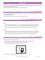
g
GE Consumer & Industrial
Multilin
CIO
Remote CAN Digital I/O Module
Instruction manual
GEK-106465A
Copyright © 2006 GE Multilin
GE Multilin
215 Anderson Avenue
L6E 1B3 Markham, ON -CANADA
T (905) 294 6222 F (905) 294 8512
GE Multilin
Avda. Pinoa, 10
48170 Zamudio SPAIN
T +34 94 485 88 00 F +34 94 485 88 45
E [email protected]
E [email protected]
Internet: www.GEMultilin.com
TABLE OF CONTENTS
1.
1.1.
OVERVIEW
IMPORTANT PROCEDURES
1.1.1.
1.1.2.
1.2.
13
13
14
MOUNTING .........................................................................................................................................14
REAR COVER DESCRIPTION ...........................................................................................................16
17
EXTERNAL CONNECTIONS ..............................................................................................................17
BOARDS
3.4.1.
3.4.2.
4.
4.1.
4.2.
INPUTS................................................................................................................................................11
OUTPUTS............................................................................................................................................11
CONTROL POWER SUPPLY .............................................................................................................11
CAN BUS .............................................................................................................................................11
ENVIRONMENTAL CHARACTERISTICS...........................................................................................11
PACKAGING AND WEIGHT ...............................................................................................................12
TYPE TESTS .......................................................................................................................................12
APPROVALS .......................................................................................................................................12
WIRING
3.3.1.
3.4.
9
9
9
10
11
HARDWARE
MODULE DESCRIPTION
MECHANICAL DESCRIPTION
3.2.1.
3.2.2.
3.3.
7
INTRODUCTION TO F650 AND F600 FAMILY OF RELAYS...............................................................7
HARDWARE ARCHITECTURE.............................................................................................................7
SOFTWARE ARCHITECTURE .............................................................................................................7
COMMUNICATIONS ARCHITECTURE................................................................................................8
PRODUCT DESCRIPTION
OVERVIEW
SUMMARY OF FEATURES
ORDERING CODE
TECHNICAL SPECIFICATIONS
2.4.1.
2.4.2.
2.4.3.
2.4.4.
2.4.5.
2.4.6.
2.4.7.
2.4.8.
3.
3.1.
3.2.
INSPECTION CHECKLIST....................................................................................................................4
SAFETY INSTRUCTIONS.....................................................................................................................6
OVERVIEW
1.2.1.
1.2.2.
1.2.3.
1.2.4.
2.
2.1.
2.2.
2.3.
2.4.
3
3
19
BOARD OPTION 1 ..............................................................................................................................19
BOARD OPTION 2 ..............................................................................................................................20
USER INTERFACES
SOFTWARE
FRONT INDICATORS
GEK-106465A
29
29
29
CIO Remote CAN Digital I/O Module
1
TABLE OF CONTENTS
5.
5.1.
INPUT/OUTPUT MODULES DESCRIPTION
CIRCUIT SUPERVISION AND CONTACT SEAL-IN CIRCUITS
5.1.1.
5.1.2.
5.2.
32
INPUT/OUTPUT BOARDS SETTINGS...............................................................................................32
INPUTS/OUTPUTS STATUS ..............................................................................................................36
ACCEPTANCE TESTS
VISUAL INSPECTION
GENERAL CONSIDERATIONS ON THE POWER SUPPLY NETWORK
ISOLATION TESTS
INDICATORS
POWER SUPLY TESTING
COMMUNICATION WITH THE MASTER UNIT
INPUTS AND OUTPUTS
6.7.1.
6.7.2.
6.7.3.
6.7.4.
2
CIRCUIT SUPERVISION.....................................................................................................................31
CONTACT SEAL-IN ............................................................................................................................31
CONTROL SETTINGS FOR INPUTS/OUTPUTS
5.2.1.
5.2.2.
6.
6.1.
6.2.
6.3.
6.4.
6.5.
6.6.
6.7.
31
31
39
39
39
40
40
40
41
41
DIGITAL INPUTS.................................................................................................................................41
CONTACT OUTPUTS .........................................................................................................................42
CIRCUIT CONTINUITY SUPERVISION INPUTS ...............................................................................42
LATCHING CIRCUITS.........................................................................................................................42
CIO Remote CAN Digital I/O Module
GEK-106465A
OVERVIEW
1. OVERVIEW
1.1.
IMPORTANT PROCEDURES
To help ensure years of trouble free operation, please read through the following chapter for information to help guide
you through the initial installation procedures of your new relay.
!
BEFORE ATTEMPTING TO INSTALL OR USE THE RELAY, IT IS IMPERATIVE THAT ALL WARNINGS AND
CAUTIONS IN THIS MANUAL ARE REVIEWED TO HELP PREVENT PERSONAL INJURY, EQUIPMENT
CAUTION: THE OPERATOR OF THIS INSTRUMENT IS ADVISED THAT IF THE EQUIPMENT IS USED IN A
MANNER NOT SPECIFIED IN THIS MANUAL, THE PROTECTION PROVIDED BY THE EQUIPMENT MAY BE
IMPAIRED
FIGURE 1-1 CIO FRONT VIEW
Installation must be according to the national electric code of the appropriate country
GEK-106465A
CIO Remote CAN Digital I/O Module
3
OVERVIEW
1.1.1.
INSPECTION CHECKLIST
- Open the relay packaging and inspect the relay for physical damage.
Refer to the label on the side of the relay verifies that the model number is the correct model ordered.
FIGURE 1-2 IDENTIFICATION LABEL (A4454P5)
- Please ensure that you receive the following items with your CIO unit:
- Mounting screws for rear terminals and for fixing the relay to a cabinet
- Wiring diagram
For product information, instruction manual updates, and the latest software updates, please visit the GE Multilin
Home Page www.GEMultilin.com.
4
CIO Remote CAN Digital I/O Module
GEK-106465A
OVERVIEW
Note: If there is any physical damage detected on the relay, or any of the contents listed are missing, please
contact GE Multilin immediately at:
EUROPE, MIDDLE EAST AND AFRICA:
GE MULTILIN
Avda. Pinoa, 10
48170 Zamudio, Vizcaya (SPAIN)
Tel.: (34) 94-485 88 00, Fax: (34) 94-485 88 45
E-mail: [email protected]
AMERICA, ASIA AND AUSTRALIA:
GE MULTILIN
215, Anderson Avenue
L6E 1B3 Markham, ON (CANADA)
Tel.: +1 905 294 6222, Fax: +1 905 201 2098
E-mail: [email protected]
The information provided herein does not intend to cover all details of variations of the equipment nor does
it take into account the circumstances that may be present in your installation, operating or maintenance
activities.
Should you wish to receive additional information, or for any particular problem that cannot be solved by
referring to the information contained herein, please contact GENERAL ELECTRIC MULTILIN.
GEK-106465A
CIO Remote CAN Digital I/O Module
5
OVERVIEW
1.1.2.
SAFETY INSTRUCTIONS
The CIO ground screw located on the rear of the unit must be correctly grounded.
This is required not only for personal protection, but also for avoiding a voltage difference between the CIO serial port
and the master unit port, which could produce anomalies in communication.
GE Multilin will not be responsible for any damage in the relay or connected equipment whenever this elemental
safety rule is not followed.
6
CIO Remote CAN Digital I/O Module
GEK-106465A
OVERVIEW
1.2.
OVERVIEW
1.2.1.
INTRODUCTION TO F650 AND F600 FAMILY OF RELAYS
This platform of relays has been designed to meet the goals that are appearing nowadays in the environment of new
substations. Historically, protection, control and metering functions have been performed by electromechanical
elements at the beginning, then static devices, and finally by digital equipment able to integrate all these functions in
a single device, called IED (Intelligent Electronic Device).
Due to the huge number of signals to be controlled and monitored nowadays in a substation environment, there is a
new need for a great number of digital inputs and outputs to retrieve states and to signal or perform all different
operations. CIO units respond to this need, allowing connection to F650 and F600 IEDs, and increasing the number
of available inputs and outputs depending on the connected equipment.
1.2.2.
HARDWARE ARCHITECTURE
CIO units incorporate a series of interconnected modules to operate. These modules are a power supply and
input/output boards.
CIO
BUS
Contact Inputs
Contact Outputs
FIGURE 1-3 HARDWARE ARCHITECTURE
As shown on the diagram above, Contact Inputs/Outputs are signals associated to physical input/output contacts in
the relay, and their status is sent/received through the CAN BUS of the associated equipment, F600 or F650.
This CAN connection to the master unit can be made through fiber optic cable or through copper cable.
CIO units can incorporate up to two I/O boards, each of which must have a unique address in the system. For this
purpose, there is a switch at the rear of the unit with 16 positions (0 to F), that allows indicating the address for board
H. The address of board J is fixed to “board H address + 1”.
1.2.3.
SOFTWARE ARCHITECTURE
Each I/O board includes a microprocessor that manages communication with the master unit, as well as sampling
and activation of the corresponding inputs and outputs.
The firmware (software embedded in the boards) has been designed using object oriented programming techniques
(ODD/OOP). These techniques are based on the use of objects and classes, and provide the software architecture
with the same characteristics as the hardware architecture, i.e., modularity and flexibility.
GEK-106465A
CIO Remote CAN Digital I/O Module
7
OVERVIEW
1.2.4.
COMMUNICATIONS ARCHITECTURE
CIO units incorporate a CAN BUS port in two physical media: glass fiber optic and cable. The fiber optic port allows
connection to the master unit for a single CIO unit. For connections including several CIO units, the cable port must
be used. If the master unit is a F650, then communication must always be in fiber optic.
8
CIO Remote CAN Digital I/O Module
GEK-106465A
PRODUCT DESCRIPTION
2. PRODUCT DESCRIPTION
2.1.
OVERVIEW
The CIO module is an input/output extension for F650 and F600 units. Using this module, the number of available
inputs/outputs can be increased, these inputs/outputs operation being identical to the one of the original I/Os in
the master unit.
The CIO module has been designed to be installed close to the substation switchgear, and connected to the main
unit through a CAN bus in fiber optic or cable. Fiber optic connection provides total immunity against
electromagnetic disturbances, as well as simplified wiring and commissioning.
CIO module I/O configuration and management are performed exclusively from the master unit. This master unit
manages the CIO inputs and outputs in the same way as its own.
2.2.
SUMMARY OF FEATURES
INPUTS
Inputs programmable from the master unit.
Programmable activation voltage level
Programmable debounce time for each inputs group
Possibility to select positive or negative activation logic
Possibility to select pulse or level activation.
OUTPUTS
Outputs programmable from the master unit
Possibility to select positive or negative activation logic
Selectable pulse mode activation
Selectable latched configuration
Breaker tripping and Closing circuits supervision
GEK-106465A
CIO Remote CAN Digital I/O Module
9
PRODUCT DESCRIPTION
2.3.
ORDERING CODE
CIO units are available in 1/3 19’’ rack, 6 units high, and it includes a power supply module and a communication
module, plus a maximum of two I/O modules. Each of these modules can be supplied in different versions, which
must be specified when ordering. The required information to detail the requested unit is shown on the table below:
TABLE 2-1 ORDERING CODE
CIO
H
-
J
-
-
-
DESCRIPTION
I/O board 1 in slot H
1
16 digital inputs + 8 outputs
2
8 digital inputs + 8 outputs + 2 trip/close circuit supervision
circuits
4
32 digital inputs
5
16 digital inputs + 8 analog inputs
I/O board 1 in slot J
0
None
1
16 inputs + 8 outputs
4
32 digital inputs (See Note 1)
5
16 digital inputs + 8 analog inputs (See Note 1)
Auxiliary Voltage
LO
24-48 Vdc (range 19.2 - 57.6)
HI
110-250 Vdc (range 88-300)
120-230 Vac (range 96-250)
Environmental Protection
H
Harsh (Chemical) environment conformal coating
(1) The digit selected for option J must be equal or higher than the digit selected for option H.
CIOH1J5**: is a valid selection
CIOH5J1**: is an invalid selection
10
CIO Remote CAN Digital I/O Module
GEK-106465A
PRODUCT DESCRIPTION
2.4.
TECHNICAL SPECIFICATIONS
TECHNICAL SPECIFICATIONS ARE SUBJECT TO CHANGE WITHOUT NOTICE
2.4.1.
Activation range:
Programmable from 1 up to 255 Vdc in steps of 1 V
Impedance
> 100 kOhm
Load for voltage supervision inputs
2 mA + V/100 kOhm
Acknowledgement time
<1 m
Debounce time:
1 to 50 ms in steps of 1 ms
2.4.2.
Permanent current
16 A
Closing current
60 A during 1 second
Opening current
0.3 A with L/R = 40 ms at 125 Vdc
INPUTS
OUTPUTS
0.25 A with L/R = 40 ms at 250 Vdc
2.4.3.
CONTROL POWER SUPPLY
LO (low range)
Range:
24 to 48 Vdc (from 24 Vdc – 15% to 48 Vdc + 20%)
HI (high range)
Range:
110 to 250 Vdc (from 110 Vdc – 15% to 250 Vdc + 20%)
110 to 240 Vac (from 110 Vac – 15% to 240 Vac + 20%)
Consumption:
5 W typical
0.25 W more per each activated output.
Interruptions:
Typical 100 ms, without unit reset.
2.4.4.
Baudrate:
125 kbits per second
Media:
Glass fiber optic multimode with ST connectors.
CAN BUS
Maximum recommended length 1Km
3 wire cable connection
Maximum recommended length 500m
2.4.5.
ENVIRONMENTAL CHARACTERISTICS
Operation temperature:
- 10°C to + 60°C
Storage temperature:
- 40°C to + 80°C
Humidity:
95% without condensing.
GEK-106465A
CIO Remote CAN Digital I/O Module
11
PRODUCT DESCRIPTION
2.4.6.
Net weight:
2.5 kg
Packaged:
3.5 kg
PACKAGING AND WEIGHT
Package dimensions (WxHxD): 30x40x40 cm
2.4.7.
TYPE TESTS
CATEGORY
STANDARD
CLASS TEST
EMC
IEC 1000-4-8 EN61000-4-8
IV
Power
frequency
immunity test.
IEC 1000-4-10 EN61000-4-10
4
Damped oscillatory field immunity test
IEC 1000-4-3 IEC60255-22-3
III
Radiated, radio-frequency
electromagnetic field immunity test
IEC 1000-4-3
3
Digital radiofrequency electromagnetic
field
IEC 1000-4-2 EN 61000-4-2 IEC6025522-2
III
Electrostatic discharge immunity test
IEC 1000-4-16
4
Test for immunity to conducted common
mode disturbances in the frequency
range 0Hz to 150 kHz immunity test.
IEC 1000-4-5
4
Surge immunity test
IEC 1000-4-12 IEC 60255-22-1
III
Noise 1 MHz.
immunity test.
IEC 1000-4-4 EC 61000-4-4 IEC6025522-4
IV
Electrical fast transient/burst immunity
test
IEC 1000-4-6 IEC60255-22-6
III
Immunity to conducted disturbances,
induced by radio-frequency fields
EMC Emisivity
IEC 60255-25 EN55022
B
Conducted and radiated emissions class
B
Product
IEC60255-5
2 kV
magnetic
Oscillatory
field
waves
Insulation
IEC60255-5
6kV .5J Impulse test
IEC60255-11; IEC61000-4-29
100 ms Power supply interruptions
CIO has been designed to comply with the highest existing requirements. More specifically, UNIPEDE
recommendations for high voltage substations are followed.
2.4.8.
APPROVALS
ISO9001 Registered system.
CE marking: Meets the CE standards relevant for protections.
12
CIO Remote CAN Digital I/O Module
GEK-106465A
HARDWARE
3. HARDWARE
3.1.
MODULE DESCRIPTION
Serial CAN BUS
DIGITAL
I/O
Optional
DIGITAL
I/O
Power Supply
FIGURE 3-1 BLOCK DIAGRAM
F650 units incorporate the following modules:
Power supply
Input/Output module
Optionally, a second I/O module can be added.
A relay connected to the low voltage side of the power supply monitors this voltage. The three contact terminals,
normally open, common, and normally closed, are available at the external connector terminals. This relay monitors
only the power supply integrity.
This is a “fly-back” type power supply, providing high efficiency, stability and reliability thanks to the maturity of this
technology. There are two available ranges, Hi and Low, in order to optimize efficiency and general performance,
including the capability to tolerate auxiliary voltage interruptions (dips).
Oversized components highly resistant to temperature are used. For example, all capacitors are specified to stand up
to 105ºC, transformer components are specially designed to stand up to 180ºC, the used MOSFET transistor is of
very low resistance, supports high voltage and is refrigerated by an oversized heat sink. This allows supporting
extremely high temperatures, and prolonged overloads such as the ones occurring at batteries in deep charge mode
(much higher than the maximum voltage shown in the Technical Characteristics section).
High capacity capacitors are also used, providing high tolerance to prolonged dips, 100ms, even in the most
unfavorable consumption conditions. This allows the relay to continue with normal operation without undesired resets,
which would cause a long time of protection unavailability
GEK-106465A
CIO Remote CAN Digital I/O Module
13
HARDWARE
3.2.
MECHANICAL DESCRIPTION
The model number and electrical characteristics of the unit are indicated on the label located on the right side of the
relay case.
The metallic case of the unit is highly resistant to corrosion. It is made of stainless steel (AISI 304), coated with an
epoxy layer, and the rest of the metallic pieces are covered with a high quality resistive coating that has successfully
passed at least 96 hours in the salt spray chamber (S/N ASTM B-117).
The front of the relay is made of a conductor thermoplastic, flame retardant (V0), highly resistive material, which
guarantees the unit’s immunity to all kinds of EMI/RFI/ESD interferences. As well, an IP51 (IEC 529) protection
degree against dust and water through the front and with the relay mounted in the panel.
In order to guarantee safety and preventing access to the unit by unauthorized personnel, the front communications
port and the operation mode key are protected by a sealable cover.
3.2.1.
MOUNTING
The unit is designed for both semi-flush mounting with the terminals on the back, and rear panel mounting, with the
terminals towards the front. In both cases the relay should be secured to the panel with the M6 screws provided with
the unit.
FIGURE 3-2 SEMI-FLUSH MOUNTING
14
CIO Remote CAN Digital I/O Module
GEK-106465A
HARDWARE
FIGURE 3-3 REAR PANEL MOUNTING
5,3"
134,0
4,5"
114,0
,3"
O 0
7,0
7,5"
190,5
10,3"
262,0
FIGURE 3-4 DRILLING DIMENSIONS
GEK-106465A
CIO Remote CAN Digital I/O Module
15
HARDWARE
3.2.2.
REAR COVER DESCRIPTION
Unit wiring is performed through the terminal blocks located on the rear.
The rest of the terminal blocks for power supply, inputs/outputs, incorporate high quality connectors with the capacity
to withstand a rated current of 15 A at 300 V. These terminal blocks admit a cable section of up to 2.5 mm2 (AWG
12).
16
CIO Remote CAN Digital I/O Module
GEK-106465A
HARDWARE
3.3.
WIRING
3.3.1.
EXTERNAL CONNECTIONS
CIO units can hold up to two I/O modules. Each of these modules can be selected between the following options:
Option 1:
Board with 16 inputs and 8 outputs.
Option 2:
Board with 8 digital inputs, 4 circuit supervision outputs, 6 conventional outputs, and two current
sensing outputs
Each model has a different wiring diagram, as follows:
FIGURE 3-5 WIRING DIAGRAM FOR MODELS CIOH2J1 (226B5113F1)
GEK-106465A
CIO Remote CAN Digital I/O Module
17
HARDWARE
FIGURE 3-6 WIRING DIAGRAM FOR MODEL CIOH1J1 (226B5113F2)
18
CIO Remote CAN Digital I/O Module
GEK-106465A
HARDWARE
3.4.
BOARDS
3.4.1.
BOARD OPTION 1
CIO I/O board option 1 includes 16 inputs grouped in two series of 8 inputs with a common, and 8 conventional
inputs.
FIGURE 3-7 shows the location of terminals for both types of board:
19
20
21
22
23
24
25
26
27
28
29
30
31
32
33
34
35
36
V
V
V
V
O1
O1
O2
O2
O3
O3
O4
O4
O5
O5
O6
O6
I
1
2
3
4
5
6
7
8
9
10
11
12
13
14
15
16
17
18
MIXED
SUPERVISION
1
2
INPUTS
CC1
COIL 1
CC2
52/a
CC3
COIL 1
CC4
52/b
CC5
CC1
CC6
CC2
CC7
CC3
CC8
CC4
COMMON 1/8 COMMON 1/4
COMMON 9/16 COMMON 5/8
CC9
CC5
CC10
CC6
CC11
CC7
CC12
CC8
CC13
COIL 2
CC14
52/a
CC15
COIL 2
CC16
52/b
OUTPUTS
I SENS
O7
O7
I
TERMINA
O8
I SENS
O8
FIGURE 3-7 LOCATION OF TERMINALS
GEK-106465A
CIO Remote CAN Digital I/O Module
19
HARDWARE
3.4.2.
BOARD OPTION 2
Option 2 I/O board includes two groups of 4 inputs with one common, in terminals 9 to 10. It also includes 6 auxiliary
outputs, in terminals 19 to 30 with normally open contacts and two current sensing (latching) outputs.
Besides, there are 2 groups of inputs for trip circuit supervision. The first group includes two isolated digital inputs,
terminals 1-2 and 3-4. The second group, symmetrical and identical to the first, is formed by isolated voltage inputs
15-16 and 17-18.
Inputs in both groups are wet contacts, this means they need to receive a positive in the terminal labeled as + coming
from a power supply whose negative is connected to the terminal labelled as -.
Using voltage detectors and current sensing, it is possible to implement several trip or close circuit supervision
schemes, as well as protection of the unit output contact.
In order to implement these schemes, it is not necessary to perform any setting in the unit. Internal functions are
always operative and provide the following logic operands:
OPERAND
DESCRIPTION
CONTACT
(Va_COIL1)
INPUT_00_08 Active when voltage is detected in terminals 1 - 2 (circuit 1)
CONTACT
(Vb_COIL1)
INPUT_00_09 Active when voltage is detected in terminals 3 - 4 (circuit 1)
CONTACT
(Va_COIL2)
INPUT_00_10 Active when voltage is detected in terminals 15 - 16 (circuit 2)
CONTACT
(Vb_COIL1)
INPUT_00_11 Active when voltage is detected in terminals 17 - 18 (circuit 2)
CONTACT
(O7_SEAL)
INPUT_00_12 Active if current is detected by sensor in output O7 (F31-F33)
CONTACT
(O8_SEAL)
INPUT_00_13 Active if current is detected by sensor in output O8 (F34-F36)
CONTACT
(SUP_COIL1)
INPUT_00_14 Active when continuity is detected in circuit 1
CONTACT
(SUP_COIL2)
INPUT_00_15 Active when continuity is detected in circuit 2
A continuity failure is detected in a circuit when both voltage detectors (Va and Vb) detect lack of voltage during more
than 500 ms. This function is not influenced by the breaker status.
These operands can be associated to internal signals (virtual outputs), LEDs or unit outputs, to issue alarm signals or
to block elements, for example for blocking the Breaker close if an abnormality is detected in the trip circuit.
Available schemes are as follows:
1. Without supervision
2. With current supervision (with seal-in)
3. With simple voltage supervision
4. With double voltage supervision
5. With current and simple voltage supervision (with seal-in)
6. With current and double voltage supervision (with seal-in)
20
CIO Remote CAN Digital I/O Module
GEK-106465A
HARDWARE
The following lines describe the different types of connection to create each scheme in an easy way. As the
supervision circuits are identical, we will describe connection examples for the first group. They are also applicable to
the second group.
The symmetrical location of digital inputs is an optimization for ensuring a high isolation between groups that,
belonging to different groups could be connected to separate batteries, and therefore a greater distance between
circuits is required.
3.4.2.1. WITHOUT SUPERVISION
This is a very frequent case, and we must only wire the tripping circuit to terminals 35 and 36, leaving unused
terminals 34, 15, 16, 17, 18.
FIGURE 3-8 CIRCUIT WITHOUT TRIPPING CIRCUIT SUPERVISION (A6631F1)
GEK-106465A
CIO Remote CAN Digital I/O Module
21
HARDWARE
3.4.2.2. WITH CURRENT SUPERVISION (WITH SEAL-IN)
In this case, as shown on FIGURE 3-9, the current supervision circuit consists in a circuit connected in series with the
output contact, so that the external circuit is wired to terminals 34 and 36. This supervision circuit includes a low
impedance reed relay that is activated when the current value exceeds 100 mA, and sends a signal to the main
microprocessor. This indication can be used to produce a latching of the output relay, so that it will remain closed
while the circulating current is over 100 mA. For this purpose we don’t need to program any setting, it is enough to
wire it as shown on FIGURE 3-9.
With this scheme, in the case of a failure to open from the breaker auxiliary contact, the CIO output relay will not be
the one to open the tripping coil current, as in this case the contact may result damaged, as it is prepared for opening
currents around 0.5 A at 125 Vdc.
This latching or memory function is only guaranteed while the unit is powered.
FIGURE 3-9 CURRENT SUPERVISION OF THE TRIPPING CONTACT (A6631F2)
22
CIO Remote CAN Digital I/O Module
GEK-106465A
HARDWARE
3.4.2.3. WITH SIMPLE VOLTAGE SUPERVISION
FIGURE 3-10 SUPERVISION APPLICATION WITH AUXILIARY CONTACT 52A AND A RESISTOR (A6631F3)
GEK-106465A
CIO Remote CAN Digital I/O Module
23
HARDWARE
INTERNAL STATE
V 52/a
SUPERVISION
52 open
ON
Ok
52 closed
ON
Ok
TRIP
OFF
Ok if t < 0.5 s
TRIP with 52 open
OFF
Ok if t < 0.5 s
There is a possibility to monitor the trip circuit and trip coil continuity. This can be done by monitoring Vdc through the
output contact when this is open.
As shown on FIGURE 3-10, when the relay is not tripped, trip contact 35-36 remains open. If the breaker is closed, its
auxiliary contact 52a is closed. Therefore, a little current is flowing, about 2 mA, through terminals 15 and 16 through
the voltage detector circuit, which flows through 52/a and the tripping coil 52TC (TC = tripping coil). Current will only
circulate when there is continuity in the whole circuit, so the complete circuit is monitored, and not only the trip coil.
This circuit includes auxiliary 52/a as well as the whole wiring between the battery and the relay tripping terminals,
and between these and the breaker tripping circuit.
This is the first case shown on the table. With closed breaker, voltage is detected by V 52/a sensor, and this means
that there is continuity in the supervised circuit.
In this table, ON means that the voltage detector V52/a is active, detecting voltage presence.
Status of Involved Elements
24
Input to F650
Decision
CIRCUIT
STATUS
OUTPUT
STATUS
(F35-F36)
BREAKER
STATUS
OPERAND
CONTACT
INPUT_00_10
(Va_COIL2)
V 52/a (F15-F16)
OPERAND
CONTACT
INPUT_00_15
(SUP_COIL2)
Healthy
Open
52 closed
ON
ON
Healthy
Open
52 open
ON
ON
Healthy
Closed
52 closed
OFF
ON (if t < 500 ms)
OFF (if t > 500 ms)
Healthy
Closed
52 open
OFF
ON (if t < 500 ms)
OFF (if t > 500 ms)
Faulty
Open
52 closed
OFF
OFF (500 ms delay)
Faulty
Open
52 open
OFF
OFF (500 ms delay)
Faulty
Closed
52 closed
OFF
OFF (500 ms delay)
Faulty
Closed
52 open
OFF
OFF (500 ms delay)
CIO Remote CAN Digital I/O Module
GEK-106465A
HARDWARE
For the second case shown on the table, open breaker, its auxiliary contact 52/a remains open, and current cannot
flow through it for detecting continuity. In order to correctly monitor the circuit, a resistor must be used, not included in
the protection, connected in parallel. The value of resistance will be selected so that the V 52/a input circuit minimum
detection current flows, but not as high as to activate the breaker tripping coil. The figure shows the following
equation:
V min – 15
R = ------------------2
Where:
Vmin
Is the minimum voltage, in Volts, expected in the battery (e.g. 80% of Vn)
R
Resistance, in kilo ohms.
2
2 mA of approximate current flowing through input V 52/a
As shown in the second case in the table, with an open breaker, as current will flow through R if there is continuity in
the WHOLE tripping circuit, voltage will be detected in input V 52/a.
This works correctly in steady state. However, if the breaker trips, while it is opening, the V 52/a input signal can be
deactivated without this meaning that the circuit is not correct. This is due to the fact that the tripping relay, terminals
35-36, short circuits input V 52/a temporarily.
Therefore, if there is a trip signal, it is admitted that no signal will be detected during a period of 1 s to allow the
breaker to open, and reopen the tripping relay 35-36.
FIGURE 3-11 shows the possibility of monitoring the circuit only when the breaker is closed. In this case resistance R
will not be used, but it must be observed in the unit logic, that the corresponding signal CONTACT INPUT_00_15
(SUP_COIL2), will be activated showing a failure when the breaker is open, and therefore it will be required to
supervise the continuity failure signalling by the breaker status information.
GEK-106465A
CIO Remote CAN Digital I/O Module
25
HARDWARE
FIGURE 3-11 TRIP CIRCUIT AND TRIP COIL SUPERVISION USING AUXILIARY CONTACT 52/A. ONLY WITH
CLOSED BREAKER (A6631F5)
26
CIO Remote CAN Digital I/O Module
GEK-106465A
HARDWARE
3.4.2.4. WITH DOUBLE VOLTAGE SUPERVISION
FIGURE 3-12 SUPERVISION APPLICATION WITH AUXILIARY CONTACTS 52A AND 52B (A6631F4)
GEK-106465A
CIO Remote CAN Digital I/O Module
27
HARDWARE
INTERNAL STATE
V 52/a
V 52/b
SUPERVISION
52 open
ON
ON
OK
52 closed
ON
OFF
OK
TRIP
OFF
OFF
Ok if t < 0.5 s
TRIP with 52 open
OFF
ON
OK
Status of Involved Elements
Inputs to F650
Decision
CIRCUIT
STATUS
OUTPUT
STATUS
(F35-F36)
BREAKER
STATUS
OPERAND
CONTACT
INPUT_00_10
(Va_COIL2)
V 52/a (15-16)
OPERAND
CONTACT
INPUT_00_11
(Vb_COIL2)
V 52/b (17-18)
OPERAND
CONTACT
INPUT_00_15
(SUP_COIL2)
Healthy
Open
52 closed
ON
OFF
ON
Healthy
Open
52 open
ON
ON
ON
Healthy
Closed
52 closed
OFF
OFF
ON (if t < 500 ms)
OFF (if t > 500 ms)
Healthy
Closed
52 open
OFF
ON
ON (if t < 500 ms)
OFF (if t > 500 ms)
Defective
Open
52 closed
OFF
OFF
OFF (500 ms delay)
Defective
Open
52 open
OFF
OFF
OFF (500 ms delay)
Defective
Closed
52 closed
OFF
OFF
OFF (500 ms delay)
Defective
Closed
52 open
OFF
OFF
OFF (500 ms delay)
There is a possibility to monitor the trip circuit continuity not only via its auxiliary contact 52/a, but also with auxiliary
contact 52/b. This avoids the need to install a resistance in parallel with auxiliary 52/a. The correct connection is
shown on FIGURE 3-12.
The circuit works in a similar way to the one described in the previous section, but it uses both supervision inputs 1516 and 17-18.
The advantage in this case is that circuit supervision with 52 open is more complete, as input V 52/b is used through
contact 52/b, (that is closed when the breaker is open).
We must point out that in this scheme, the tripping contact, shown in the example as the CIO trip relay, can be the
one in the relay (terminals 35 and 36), or be provided by another protection or by the parallel of several protections.
This provides high flexibility in the use of this circuit.
The battery voltage can also be monitored, by using one of the standard digital inputs.
28
CIO Remote CAN Digital I/O Module
GEK-106465A
USER INTERFACES
4. USER INTERFACES
4.1.
SOFTWARE
CIO units need to be connected to a master unit, either an F650 or an F600. If the master unit is an F650, the CIO
can be programmed using EnerVista F650Setup program; in case of using an F600 as master unit, the CIO can be
programmed using GE-CONF software. In both cases, CIO inputs/outputs will be shown as if they were part of the
master unit, with the same programming options as the master unit I/O.
EnerVista F650Setup software provides a simple way to configure, monitor and maintain operation of F650 and the
connected CIO unit. Please refer to the F650 user manual for a more detailed reference about EnerVista F650Setup.
In the same way, please refer to GE-CONF software manual for details about programming a CIO unit connected to
an F600 master unit.
4.2.
FRONT INDICATORS
CIO units incorporate 2 LEDs on the front, one of them indicates that the unit is powered, and the other indicates
activity on the CAN bus.
GEK-106465A
CIO Remote CAN Digital I/O Module
29
USER INTERFACES
30
CIO Remote CAN Digital I/O Module
GEK-106465A
I/O MODULES DESCRIPTION
5. INPUT/OUTPUT MODULES DESCRIPTION
5.1.
CIRCUIT SUPERVISION AND CONTACT SEAL-IN CIRCUITS
5.1.1.
CIRCUIT SUPERVISION
CIO units can include type 2 boards. This type of board includes 4 voltage detectors for implementing tripping or
opening circuit supervision control logics.
5.1.2.
CONTACT SEAL-IN
The current seal-in circuit is used for verifying the current condition in a circuit during the time that the tripping contact
remains closed. If the current in the tripping circuit is maintained over 100 mA, the function is sealed independently of
the status of the function that caused the trip.
This current seal-in function in tripping circuits is mainly used in applications where auxiliary contacts 52/a (in charge
of cutting the current in the tripping circuit) are very slow. This may cause that, once the function that produced the
trip is reset, the relay contact will open before the breaker auxiliary 52/a, even if the time delay of the first has expired.
By using this function, we prevent the relay contact from cutting the current (basically inductive and high) from the
tripping circuit, which could cause damage to the unit, as these currents exceed the nominal breaking characteristics.
The circuit and the current threshold of the function are as follows:
100 mA min
I
FIGURE 5-1 CURRENT SUPERVISION
GEK-106465A
CIO Remote CAN Digital I/O Module
31
I/O MODULES DESCRIPTION
5.2.
CONTROL SETTINGS FOR INPUTS/OUTPUTS
This section explains the settings related to CIO inputs/outputs. Modification of these values is performed using the
master unit communication software, EnerVista F650Setup for F650, or GE-CONF for F600.
5.2.1.
INPUT/OUTPUT BOARDS SETTINGS
Settings relative to I/O boards are described in table 5-1:
TABLE 5-1 I/O BOARD SETTINGS
SETTING
HMI
DEFAULT
RANGE
STEP
16 INP + 8OUT
I/O board type (available only for
CIO modules)
I/O Board_X Type
NONE
8 INP + 8OUT +
SUPV
N/A
NONE
Input activation voltage threshold
Group A
Voltage Threshold A_X
80
0 – 255 V
1V
Input activation voltage threshold
Group B
Voltage Threshold B_X
80
0 – 255 V
1V
Debounce time Group A
Debounce Time A_X
15
1 – 50 ms
1 ms
Debounce time Group B
Debounce Time B_X
15
1 – 50 ms
1 ms
POSITIVE-EDGE
Input type
Input Type_X_CCY
POSITIVE
NEGATIVE-EDGE
POSITIVE
N/A
NEGATIVE
Input signal time delay
Delay Input
Time_X_CCY
Output logic type
Output Logic_X_0Z
0
0 – 60000 ms
1 ms
POSITIVE
POSITIVENEGATIVE
N/A
NORMAL
Output type
Output Type_X_0Z
NORMAL
PULSE
N/A
LATCH
Pulse Output
Time_X_0Z
Output pulse length
0
0 – 60000 ms
1 ms
Being:
X
I/O board name, depending on the CIO model.
For the I/O board selection in the relay model, associated digits to each board type are as follows:
32
ASSOCIATED DIGIT
F650PC BOARD
SETTINGS
BOARD TYPE
0
NONE
None
1
16 INP+ 8OUT
Mixed
2
8 INP +8 OUT +SUPV
Supervision
CIO Remote CAN Digital I/O Module
GEK-106465A
I/O MODULES DESCRIPTION
CCY
Is the name used for inputs in I/O boards
Mixed, 16 digital inputs: CC1….CC16
Supervision: 8 digital inputs: CC1,..., CC8
0Z
Is the name used for the different outputs in I/O boards, 8 outputs available for any of the two types of board
(01,…., 08)
Description of I/O board settings is as follows:
General Board Settings:
I/O Board Type: Selection of the I/O board type.
GEK-106465A
CIO Remote CAN Digital I/O Module
33
I/O MODULES DESCRIPTION
Settings relative to Inputs:
Input Activation Voltage Threshold: This value can be from 0 to 255 volts. There is a single setting for all inputs in
the same group (inputs sharing the same common). In mixed and supervision boards there are two groups of inputs,
called A and B.
Debounce Time: This is the debounce time set for inputs (1 to 50 ms). The debounce time is the time window for
input filtering. If an input suffers a change of level that lasts less than this set time, the change will not be considered.
There is a single setting for all inputs in the same group.
Delay Input Time: This is the delay applied to the input signal; the default value is zero, meaning no delay; the
setting range is 0 to 60000 milliseconds (1 minute). This setting is used in slow switchgear applications.
This is not a grouped setting; there is a different setting for each input. It is important not to confuse this delay input
time with the debounce time used for filtering undesired transients in the input signal. The Debounce time is always
added to the delay input time.
Input Type: Type of logic associated to the physical input. Possible settings are, positive and negative.
Positive and Negative settings correspond to signals that are activated or deactivated with the input level, considering
the delay setting. Positive-edge, and Negative-edge settings correspond to signals that are activated with the change
of the input signal; in this case, the Delay Input Time will not be considered, only the Debounce Time; this edge
signals are deactivated automatically after one PLC scan cycle. FIGURE 5-2 shows the types of signals associated to
the different input configuration types.
FIGURE 5-2. INPUT LOGIC
34
CIO Remote CAN Digital I/O Module
GEK-106465A
I/O MODULES DESCRIPTION
Settings relative to Outputs:
Output Logic_0X _XX: Type of logic applied to outputs. Possible values are positive and negative. The default
value is positive.
Output Type_0X _XX: Type of output adjusted. Possible values are normal, latched or pulse; the default value is
Normal.
Pulse Output Time_0X _XX: This is the output pulse length in case the output type is selected to be pulse; the
default value is 10000 ms.
Output Logic: Type of logic applied to outputs; possible values are Positive and Negative; the default value is
Positive. Depending on the type of setting selected, the physical output will be in the same direction (positive) or
opposite (negative) the output activation command.
Output Type: This is the set output type. Possible values are normal, latched or pulse; the default value is Normal.
Normal type follows the activation command. Pulse type delays the time, according the Pulse Output Time setting.
Latched type remains active after the activation command. The physical output reset when it is configured as latched
can be performed using a deactivation command. Such command must be configured at Setpoint > Relay
Configuration > Outputs > Contact Output Reset”.
Pulse Output Time: This is the output pulse length, applicable only to signals set as pulse type; the default value is
10000 ms and the setting range is 0 to 60000 ms (1 minute).
FIGURE 5-3 shows the types of signals associated to the different output configuration types.
FIGURE 5-3 OUTPUT LOGIC.
GEK-106465A
CIO Remote CAN Digital I/O Module
35
I/O MODULES DESCRIPTION
5.2.2.
INPUTS/OUTPUTS STATUS
Signals associated to I/O boards are divided in several groups:
Input activation signals (Contact Inputs):
Contact input activation signals can be obtained at Actual > Status > Contact Inputs > Board X, being X the
corresponding I/O board. Depending on the I/O board, inputs are represented as follows:
TABLE 5-2: INPUT STATUS
INPUT STATUS
(X: board F, G, H, J)
MIXED BOARD
(TYPE 1)
SUPERVISION BOARD
(TYPE 2)
CONT IP_X_CC1
CC1
CC1
CONT IP_ X _CC2
CC2
CC2
CONT IP_ X _CC3
CC3
CC3
CONT IP_ X _CC4
CC4
CC4
CONT IP_ X _CC5
CC5
CC5
CONT IP_ X _CC6
CC6
CC6
CONT IP_ X _CC7
CC7
CC7
CONT IP_ X _CC8
CC8
CC8
CONT IP_ X _CC9
CC9
Va_COIL1
CONT IP_ X _CC10
CC10
Vb_COIL1
CONT IP_ X _CC11
CC11
Va_COIL2
CONT IP_ X _CC12
CC12
Vb_COIL2
CONT IP_ X _CC13
CC13
O7_SEAL
CONT IP_ X _CC14
CC14
O8_SEAL
CONT IP_ X _CC15
CC15
SUP_COIL1
CONT IP_ X _CC16
CC16
SUP_COIL2
The operation logic for supervision signals (board type 2) is detailed in section 3.3.2. in this manual.
36
CIO Remote CAN Digital I/O Module
GEK-106465A
I/O MODULES DESCRIPTION
Contact Outputs activation signals:
These are the signals that mark the physical activation of contact outputs, independently from their associated logic.
They can be obtained at Actual > Status > Contact Outputs > Board X, being X the corresponding I/O board. The
output name is the same both for the mixed and supervision boards; the difference will be the symbol associated to
the slot where the board is located in the unit (slot F, G, H or J).
TABLE 5-3 CONTACT OUTPUT STATUS
CONTACT OUTPUT STATUS
(X: board F, G, H, J)
CONT OP_X_01
CONT OP_X_02
CONT OP_X_03
CONT OP_X_04
CONT OP_X_05
CONT OP_X_06
CONT OP_X_07
CONT OP_X_08
Contact Output Activation Signals (Contact Output Operates):
These are the logic signals associated to contact outputs that produce their activation. Actual > Status > Contact
Outputs Operates > Board X, being X the corresponding I/O board. The name of these outputs is the same for the
mixed and supervision boards, the only difference will be the slot where the output is located in the relay (slot F, G, H
or J). These signals can be configured at Setpoint > Relay Configuration > Outputs > Contact Output Operate.
TABLE 5-4 CONTACT OUTPUT OPERATES
CONTACT OUTPUT
OPERATES
(X: board F, G, H, J)
CONT OP OPER_X_01
CONT OP OPER_X_02
CONT OP OPER_X_03
CONT OP OPER_X_04
CONT OP OPER_X_05
CONT OP OPER_X_06
CONT OP OPER_X_07
CONT OP OPER_X_08
GEK-106465A
CIO Remote CAN Digital I/O Module
37
I/O MODULES DESCRIPTION
Contact Output Reset Signals (Contact Output Resets):
These are the logic signals associated to the contact output reset, which produce the reset of those signals previously
configured as Latched. The status of these signals is obtained at Actual > Status > Contact Outputs Resets >
Board X, being X the corresponding I/O board. The name of these outputs is the same for the mixed and supervision
boards, the only difference will be the slot where the output is located in the relay (slot F, G, H or J). These signals
can be configured at Setpoint > Relay Configuration > Outputs > Contact Output Reset
TABLE 5-5 CONTACT OUTPUT RESETS
CONTACT OUTPUT RESETS
(X: board F, G, H, J)
CONT OP RESET_X_01
CONT OP RESET_X_02
CONT OP RESET_X_03
CONT OP RESET_X_04
CONT OP RESET_X_05
CONT OP RESET_X_06
CONT OP RESET_X_07
CONT OP RESET_X_08
IO Board Status:
These signals are associated to the different I/O boards. There are internal signals that provide information about the
status of these boards, indicating whether there is any anomaly in the board, or whether the board is not available in
the relay according to the relay model. This information can be accessed at Actual > Status > IO Board Status.
TABLE 5-6 I/O BOARD STATUS
BOARD STATUS
BOARD F STATUS
BOARD G STATUS
BOARD H STATUS
BOARD J STATUS
38
CIO Remote CAN Digital I/O Module
GEK-106465A
ACCEPTANCE TESTS
6. ACCEPTANCE TESTS
6.1.
VISUAL INSPECTION
Verify that the relay has not suffered any damage during transportation, and that all screws are correctly fixed, and all
relay terminal boards are in good condition.
6.2.
GENERAL CONSIDERATIONS ON THE POWER SUPPLY NETWORK
All devices running on AC current are affected by frequency. As a non-senoidal wave is the result of a fundamental
wave plus a series of harmonics from this fundamental wave, it can be deducted that devices running on AC current
are influenced by the applied waveform.
For a correct testing of devices running on AC current, it is fundamental to use a current and/or voltage senoidal
waveform. The pureness of a senoidal wave (lack of harmonics) cannot be expressed specifically for a specific
device. However, any relay incorporating sintonized circuits, R-L and R-C circuits, will be affected by non-senoidal
waveforms.
These devices respond to the voltage waveform in a different way to the majority of AC current voltmeters. If the
power supply network used for the testing contains wide harmonics, the voltmeter and relay responses will be
different.
When the device is tested, a power supply network with no harmonics in its waveform must be used.
It is important to point out that the accuracy with which the test is performed depends on the network and on the
instruments used. Functional tests performed with unsuitable power supply network and instruments are useful to
check that the device operates properly and therefore its operating characteristics are verified in an approximate
manner.
The following sections detail the list of tests for verifying the device functionality.
GEK-106465A
CIO Remote CAN Digital I/O Module
39
ACCEPTANCE TESTS
6.3.
ISOLATION TESTS
During all tests, the screw located on the rear of the relay must be grounded.
For verifying isolation, independent groups will be created, and voltage will be applied as follows:
2000 RMS volts will be applied progressively among all terminals in a group, short-circuited between them
and the case, during one second.
2000 RMS volts will be applied progressively between groups, during one second.
WARNING: No communication circuit shall be tested for isolation.
Groups to be created will depend on the type of modules included in the CIO, selectable according to the model.
The following table shows the different groups depending on the module type:
SOURCE 1:
I/O OPTION 1
I/O OPTION 2.
G1: K10, K18
G1: (Inp. 1)1…9
G1 (Spv 1): 1...4
G2: K13, K14, K15
G2: (Inp. 2) 10…18
G2 (Inp. 1): 5...9
G3: (Out.) 19…36
G3 (Inp. 2): 10…14
G4 (Spv 2): 15...18
G5 (Out.): 19...30
G6 (Out.): 31…36
6.4.
INDICATORS
Feed the unit and verify that the Ready LED lights up.
Communicate with the master unit and verify that the communication LED lights up showing activity on the CAN bus.
6.5.
POWER SUPLY TESTING
Feed the unit to the minimum and maximum voltage. For each voltage value, verify that the alarm relay is activated
when there is voltage, and it is deactivated when there is no feed. If the power supply source incorporates AC feed,
this test will be performed also for VAC.
Voltage values to be applied will be the ones indicated below according to the relay model:
SUPPLY
40
V min.
V max.
HI
110-250 Vdc
120-230 Vac
88 Vdc
96 Vac
300 Vdc
250 Vac
LO
24-48 Vdc
20 Vdc
57.6 Vdc
CIO Remote CAN Digital I/O Module
GEK-106465A
ACCEPTANCE TESTS
6.6.
COMMUNICATION WITH THE MASTER UNIT
1. Connect the master unit to the CIO. Verify that the BUS LED blinks indicating communication between both
units.
2. Verify, using the master unit Setup program, that the CIO boards setting options are available. For example,
using an F650 as master unit, verify in EnerVista F650 Setup, that the "Actual > Inputs/Outputs > I/O
Board Status > Board H Status" and "Actual > Inputs/Outputs > I/O Board Status>Board J Status"
appear as active.
6.7.
INPUTS AND OUTPUTS
During all tests, the screw on the rear of the relay must be grounded.
6.7.1.
DIGITAL INPUTS
During this test, the user will determine the activation/deactivation points for every input in the relay for the set voltage
value of 30 Volts.
Verify that the error does not exceed +/- 10% (+10% on activation, -10% on deactivation)
Default board settings for the input test are as follows:
Settings/Control Elements/Inputs Outputs/Board X
I/O Board Type 1
Voltage Threshold A_01
30 V
Voltage Threshold B_01
40 V
Debounce Time A_01
15 ms
Debounce Time B_01
15 ms
Input Type 01 00 (CC1)
POSITIVE
...
...
Input Type 01 15 (CC16)
POSITIVE
The inputs test is completed by groups of 8 inputs, as this type of board has 2 groups of 8 inputs with the same
common. For the first 8 inputs, the voltage threshold setting is determined by Voltage Threshold A. For the next 8
inputs, the setting is Voltage Threshold B.
Inputs (or contact converters, CC1 – CC15) must also be set to POSITIVE.
I/O Board Type 2
GEK-106465A
Voltage Threshold A_01
30 V
Voltage Threshold B_01
40 V
Debounce Time A_01
5 ms
Debounce Time B_01
5 ms
Input Type 01 00 (CC1)
POSITIVE
...
...
Input Type 01 07 (CC8)
POSITIVE
CIO Remote CAN Digital I/O Module
41
ACCEPTANCE TESTS
The inputs test is completed by groups of 4 inputs, as this type of board has 2 groups of 4 inputs with the same
common. For the first 4 inputs, the voltage threshold setting is determined by Voltage Threshold A. For the next 4
inputs, the setting is Voltage Threshold B.
Inputs (or contact converters, CC1 – CC8) must also be set to POSITIVE.
6.7.2.
CONTACT OUTPUTS
The correct activation of every output will be verified.
For every output, activation command of a single contact must be given, and then verify that only that contact is
activated (Setpoint/Force IO)
For switched contacts, the change of state of both contacts shall be verified.
6.7.3.
CIRCUIT CONTINUITY SUPERVISION INPUTS
Supervision inputs will be tested as normal inputs, revising the voltage level, which will be 19 Volts.
Coil 1:
Apply 19 Vdc to both 52/a and 52/b ”Coil 1” circuit supervision inputs and verify that they are activated.
Apply -19 Vdc to both 52/a and 52/b ”Coil 1” circuit supervision inputs and verify that they are activated.
Remove voltage from both inputs and verify that it takes them 500 ms to change state (deactivate).
Coil 2:
Apply 19 Vdc to both 52/a and 52/b ”Coil 2” circuit supervision inputs and verify that they are activated.
Apply -19 Vdc to both 52/a and 52/b ”Coil 2” circuit supervision inputs and verify that they are activated.
Remove voltage from both inputs and verify that it takes them 500 ms to change state (deactivate).
6.7.4.
LATCHING CIRCUITS
Send a closing command to the latched contact.
Make circulate a current of 200 mA through the contact in series with the sensing terminal.
Send an opening command and verify that the contact does not open.
Interrupt current and check than the contact is released.
200
I
Repeat the test for the other latched contact
42
CIO Remote CAN Digital I/O Module
GEK-106465A