1
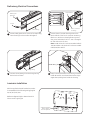
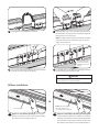
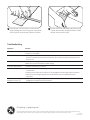
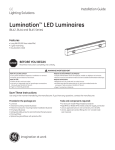
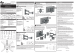
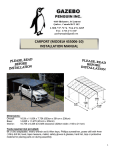
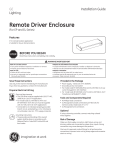
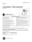
Installation Guide
GE
Lighting
Lumination LED Luminaires
TM
(BL Series - Continuous Run Option)
BEFORE YOU BEGIN
Read these instructions completely and carefully.
WARNING/AVERTISSEMENT
RISK OF ELECTRIC SHOCK
• Turn power off before inspection, installation or removal.
• Properly ground electrical enclosure.
RISK OF FIRE
• Follow all IEC and local codes.
• Use only IEC approved wire for input/output connections.
Minimum size 14 AWG (0.75mm2).
Save These Instructions
Provided in the Package
Use only in the manner intended by the manufacturer. If you
have any questions, contact the manufacturer.
• Luminaire without end covers
• Universal mounting brackets (4 pieces)
• M3x12mm screws for mounting bracket installation (8 pieces)
• M3 wingnut (8 pieces)
• Ceiling grid screw for grid and bracket fixing (4 pieces)
• M4x16mm screw for bracket to bracket fixing (2 pieces)
• M4 nut for bracket to bracket fixing (2 pieces)
• Primary diffuser
• Optional low glare diffuser with protective foil
• Joiner pins (2 pieces)
Important
• 120-127V 60Hz - maximum 33 meters of luminaires (various unit) can be connected on a single through wiring run.
• 220-240V 50/60Hz - maximum 64 meters of luminaires can be connected on a single through wiring run.
• Please see technical data sheet for electrical properties to ensure
safe installation.
• Under any circumstance, maximum driver current through connected fixtures shall not exceed 12 A.
Prepare Electrical Wiring
Electrical Requirements
• The LED driver must be supplied with
120-240 VAC, 50/60 Hz and connected to an
individual properly grounded branch circuit.
Use min. 600V 75°C supply conductor.
Grounding Instructions
• The grounding and bonding of the overall
system shall be done in accordance with
IEC and local codes.
imagination at work
Tools and Components Required
• For end cover install: Philips headed screwdriver
• For bracket to bracket fixing: 7mm wrench or socket
• BL Series 4’’ Wide End Covers – SKU 85598
• BL Series CE Continuous Leader Cable (1-10V) –SKU 85601
• BL Series CE Continuous Leader Cable (DALI) - SKU 85675
Wiring Diagrams
Optional Installation: 1-10 Volt Dimming or DALI Lighting Controller
Follow diagram A for 0-10 V or diagram B for DALI.
Line (black)
Neutral (white)
Ground (green)
(1-10) + violet
Line
Line (black)
Neutral
Neutral (white)
Ground
(1-10) - grey
A
1-10V wiring diagram
PSU
(1-10V) -
Ground (green)
DALI
DALI 1 violet
DALI/(1-10V) +
Line
Neutral
Ground
DALI 2 orange
B
DALI wiring diagram
PSU
(1-10V) DALI
DALI/(1-10V) +
Preliminary Electrical Connections
Terminal block
Dimming line
(optional)
Black
White
Green/yellow
Grey or Orange
Violet
AC line
Line-in connector
accessory
First unit only
1
Loosen cable gland nuts to insert AC line. Optionally,
insert dimming line into smaller cable gland.
2
Connect the AC line and dimming wires to the
terminal block of the line-in connector accessory:
Black to L1, White to N, Green/yellow to ground,
Grey to D1 and Violet to D2 for 1-10V or Orange to
D1 and Violet to D2 for DALI.
Note: Use BL Series CE Continuous Leader Cable (110V) SKU 85601 or BL Series CE Continuous Leader
Cable (DALI) SKU 85675.
Through wiring
3
Connect the accessory kit to the through wiring.
Push wires into fixture.
4
Snap in the terminal block to the factory mounted
holder. Be careful not to break the wires at a high
angle when pushing them inside the housing.
Luminaire Installation
With the supplied universal bracket the product
is compatible with the following USG type grids:
DX, DXI, DXT, DXF, DXM.
DX
Reference diagram (right) to determine which
hole to use for a given grid.
DXM/
DXT(G)
DXT(F)
DXI
Safety screw holes.
One is needed,
more are optional.
DXF
DXM/
DXT(G)
DXF
DXI
DX
DXT(F)
Joiner pin
20-22mm
1
For the luminaires that will be in the middle of the
run, insert two pins into one end only. Slide pins into
the bottom screw grooves, leaving approximately
20-22mm exposed.
2
Pre-install the two M3x12 mm screws with the
wingnuts into bracket. The screws should be in the
same hole type.
Do not
tighten yet
Must use star
washer on top hole
Groove
3
4
Insert four mounting brackets (two at each end)
into grooves on both sides of luminaire. Position
brackets approximately 2-3mm from ends. Do
not tighten wingnuts yet.
Fasten one end cover on the first and last
luminaires only with four M3 screws. Always use a
star washer under one of the top screws to ensure
ground continuity.
Note: The luminaires between the opening and
closing units do not require end covers.
End cover
No end covers
Middle luminaire(s)
(up to 8 units)
First luminaire
Pins
Place luminaires into ceiling grid.
Last luminaire
Pins
Ceiling grid
5
End cover
Pin
6
7
Plug together wires between luminaires.
Carefully align pins of one luminaire with grooves of
next luminaire, then push them completely together,
taking care not to pinch wires.
Note: A rubber mallet may be required to complete
this step. Hammer the luminaires only on the top
edge, not the bottom.
One safety screw per
bracket is mandatory,
additional screws are
optional
8
9
Join mounting brackets together with M4 hex head
screw and nut. Also tighten wingnuts.
For added safety, use additional ceiling grid screws
to permanently fix brackets to grid.
WARNING
Risk of Injury. Improper mounting bracket installation
may cause injury or property damage.
Diffuser Installation
Top: Primary diffuser with no film
OR
Primary diffuser
1A
Option A - one diffuser (primary): Tilt and slide
diffusers into base of luminaires. The last diffuser
will need to be trimmed (see Step 2).
Bottom: Anti-glare diffuser
with green film faces up
(remove film before sliding in)
1B
Option B - two diffusers (primary and anti-glare):
Tilt and slide both diffusers into base of luminaires,
making sure the diffuser with the green protective
film is placed on the bottom (remove film first). The
last diffusers will need to be trimmed (see Step 2).
2
Place diffuser to be trimmed on a clean surface.
Apply masking tape over cutting area. Score plastic
with utility knife to about 50% of plastic thickness.
3
Position score over table edge and carefully snap
off end. Remove tape, file edge, and clean. Install
diffuser as instructed in Step 1.
Troubleshooting
Symptom
Solution
Luminaire does not light
• Check input voltage and check power supply input/output connections.
• Check circuit breaker.
Luminaire is dim
• Dimming wire connection shall be checked and if connection is not proper, reconnect it.
If wire is harmed, replace it with an intact one. Also check that dimming wires are not in short circuit.
Luminaire is blinking
• Ensure power supply temperature does not exceed its maximum rating.
• Refer to the tc point located on power supply.
Luminaire does not dim
• Check dimming wire connection.
Luminaires will not turn on
• Check that the color of the supply side wires match the color of the wires they are
connected to.
• Check that the LED driver connector is fully engaged to the LED light engine connector.
• Check that the LED light engines are connected at the junction between the two
luminaires.
Luminaire on through
wiring will not turn on
• Check that the through wiring connector from the previous fixture in the linear row is fully
engaged to the malfunctioning luminaire.
GE Lighting • gelighting.com
GE Lighting is a subsidiary of the General Electric Company. Lumination is a trademark of GE Lighting Lighting Solutions, LLC. The GE brand and logo are trademarks of the General Electric Company.
© 2013 GE Lighting. Information provided is subject to change without notice. All values are design or typical values when measured under laboratory conditions.
01333785
IND076-082313