1
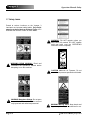
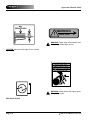
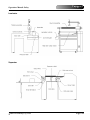
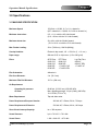
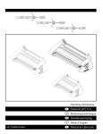
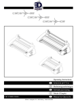
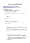
®
Voyager 3
OPERATION MANUAL
Part Number: 930-032 REV: A REV DATE: 04-02-04
©2004 GENERAL BINDING CORPORATION ALL RIGHTS RESERVED.
Do not duplicate without written permission.
Voyager 3
Operations Manual
TABLE OF CONTENTS
1.0 Safety
1.1 Explanation of symbols
1.2 General Rules of safety
1.3 Emergency Stops
1.4 Safety Shields
1.5 Pneumantics
1.6 Heat
1.7 Safety labels
1.8 Know Your laminator
1-1
1-2
1-4
1-4
1-5
1-5
1-6
1-10
2.0 Warranty
2.0 Limited 90-day warranty
2-1
3.0 Specifications
3.1 Machine Specification
3.2 Feeder Specifications
3.3 Feeder Pump and Specifications
3.4 Heater
3-1
3-2
3-3
3-4
4.0 Installation
4.1 Pre-installation
4.1.1 Suggested Floor Layout
4.1.2 Connections
4.2 Receiving the crates
4.3 Uncrating
4.4 Positioning the components
4.4.1 Component placement
4.5 Safety Checklist
4-1
4-3
4-4
4-5
4-5
4-6
4-8
4-9
5.0 Operations
5.1 Feeder
5.2 Laminator
5.2.1 Control Panel
5.2.2 Unwind controls
5.3 Stacker
5.4 Vacumn pressure
5.5 Heater
5-3
5-6
5-7
5-10
5-15
5-16
5-16
6.0 Applications
6.1 Start-up procedure
6.2 Shut down procedure
6-1
6-3
7.0 Maintenance and troubleshooting
7.1 Daily cleanng
7.2 Periodical Maintenance
7.3 Troubleshooting
7-1
7-1
7-2
8.0 Appendix
Appendix A — Heater Manuals
Appendix B — Pump Manual
Appendix C — Diagrams
8-3
8-5
8-7
2004 General Binding Corporation
I
II
2004 General Binding Corporation
Operations Manual
Voyager 3
The information in this publication is provided for reference and is believed to be
accurate and complete. GBC is not liable for errors in this publication or for incidental or
consequential damage in connection with the furnishing or use of the information in this
publication, including, but not limited to, any implied warranty of fitness or merchantability
for any particular use.
GBC reserves the right to make changes to this publication and to the products
described in it without notice. All specifications and information concerning products are
subject to change without notice.
Reference in this publication to information or products protected by copyright or
patent does not convey any license under the rights of GBC or others. GBC assumes no
liability arising from infringements of patents or any other rights of third parties.
This publication is copyrighted © 2003 by GBC. All rights reserved. The information
contained in this publication is proprietary and may not be reproduced, stored, transmitted,
or transferred, in whole or in part, in any form without the prior and express written
permission of GBC.
2004 General Binding Corporation
III
IV
2004 General Binding Corporation
Voyager 3
Operations Manual: Safety
1.0 Safety
CAUTION: Do not attempt to operate your
Voyager 3 Laminator until you completely
read and understand this and all related
Operations Manual.
Your safety, as well as the safety of others, is important to GBC. This section contains important safety
information pertaining to the Voyager 3 Laminator
which must be adhered to while operating, cleaning
and performing basic maintenance in and around
the machine.
For important safety information regarding the
Becker Pump, Soma Feeder or Sterlco
Water Temperature Control Unit, read the
operation manual provided by each of the components manufacturer.
CAUTION: CHANGES OR MODIFICATIONS NOT EXPRESSLY
APPROVED BY GENERAL BINDING CORPORATION COULD VOID
YOUR AUTHORITY TO OPERATE
THE EQUIPMENT.
Canada Class A Notice - Avis Canada,
Classe A
This Class A digital apparatus complies with
Canadian ICES-3.
Cet appareil numérique de la classe A est conforme à la norme
NMB-003 du Canada.
1.1 Explanation of symbols
FCC NOTE
This equipment has been tested and found to
comply with the limits for a
Class A digital device, pursuant to Part 15 of
the FCC Rules. These limits
are designed to provide reasonable protection
against harmful interference
when the equipment is operated in a commercial environment.
This equipment generates, uses, and can radiate radio frequency energy and,
if not installed and used in accordance with the
Operator Manual, may cause
harmful interference to radio communications.
Operation of this equipment in
a residential area is likely to cause harmful
interference in which case the
user will be required to correct the interference
at his/her own expense.
INFORMATION: This symbol used to
inform you of important information pertaining to the current subject.
CAUTION: When you see this symbol,
use caution to avoid harm to you, or others around you.
WARNING: This symbol is used to inform
you of a dangerous situation and tells you
how to avoid harm to you, others around
you or to the equipment
ELECTRICAL HAZARD: This symbol is
used to prevent an electrical shock condition that may be caused by an operators
action or machine function.
CAUTION: When you see this word without a symbol, it means the action described may result in
machine damage.
If for any reason you are unsure of what a symbol
represents, contact your local sales/service representative for further explanation.
2004 General Binding Corporation
Page 1-1
Voyager 3
1.2 General rules of safety
ELECTRICAL HAZARD: Do not operate
the laminator if power cord is damaged or
frayed.You can be severely shocked, electrocuted or cause a fire.
ELECTRICAL HAZARD: Employ a
licensed electrician to provide electrical
requirements for the laminator.
ELECTRICAL HAZARD: Employ a
licensed plumber to provide tap and
drain requirements for the laminator.
ELECTRICAL HAZARD: Do not use liquid or aerosol cleaners on the laminator.
Do not spill liquid of any kind on the laminator. You can be severely shocked, electrocuted or cause a fire.
ELECTRICAL HAZARD: Never disconnect any cable on the laminator
while power is supplied. Servicing
should be left to qualified service representatives only.
Operations Manual: Safety
WARNING: Do not operate this laminator
if you are not physically, psychologically or
emotionally fit. Do not operate this
machine until you have been trained and
read this manual in it’s entirety.
WARNING: Do not wear ties, loose fitting
clothes or dangling jewelry while operating or servicing the laminator. These items
can get caught in the nip and choke you or
you can be crushed or burned.
WARNING: Never tamper with the safety
devices to increase the laminator’s production capacity. In the event a safety
device should fail, never attempt to
bypass it for operation. Consult a service
representative immediately.
WARNING: To prevent injury to others
working around the laminator, only one
person may control the functions of the
laminator during operation or servicing.
CAUTION: The operating environment
must be free of dust, flammable liquids
and vapors.
ELECTRICAL HAZARD: Do not attempt
to repair or service the laminator.
Servicing should be left to qualified service
representatives only.
Page 1-2
2004 General Binding Corporation
Operations Manual: Safety
CAUTION: Vapor build up or stored flammable liquids can cause a fire. Excessive
dust can damage the laminator.
CAUTION: Exercise extreme caution
when working around or replacing the
film cutter blade. This blade is sharp and
cut you.
CAUTION: Keep feet away from the feeder pile table when lowering to ground
level.
CAUTION: Avoid contact with the heat
roller during webbing, operation, un-webbing, changing film or after heat has been
removed from the laminator.
CAUTION: Always observe all warning
labels placed at various points on the
laminator. If you do not completely understand a label, contact your local service
representative for further explanation.
CAUTION: Always follow proper shutdown procedure as described in this
manual when turning the laminator off.
CAUTION: Only use materials specified
in this manual for cleaning of the laminator and routine maintenance.
2004 General Binding Corporation
Voyager 3
CAUTION: The laminator may only be
moved by a qualified service representative. Improper disconnection or reconnecting can result in injury to you and/ or damage to the laminator.
CAUTION: Never use this machine for
any other purpose than its intended
design and function. You may be injured.
The following actions can result in
machine damage.
CAUTION: Do not make any modifications to this
laminator. Unauthorized changes will void your warranty and may cause extensive repairs or create
poor output quality.
CAUTION: Do not locate the laminator where air is
blowing directly on the machine. The air flow can
cool the rollers unevenly and result in poor output
quality.
CAUTION: Only use acceptable materials through
this laminator. Unacceptable materials may cause
damage to the rollers or cause poor output quality.
CAUTION: Do not place the laminator on uneven
surfaces. This will effect the operation of the laminator and will result in poor output quality.
INFORMATION: Any concerns for safety
or operation should be brought to the
attention of your local service representative immediately.
Page 1-3
Voyager 3
Operations Manual: Safety
Jog/Slow Speed w/Guard Open
1.3 Emergency stops (E-Stop)
The Voyager 3 is equipped with three E-Stops. One
is located on the feeder next to the feeder pile table
controls, the second is located on the laminator control panel and the third is located on the top of the
laminator electrical box.
The Jog and Reset buttons must be held simultaneously to allow the slow speed jogging with the safety guard open. Speed is monitored by relay for safety purposes.
1.4 Safety shields
The two safety shields, one covering the main roller
and the second covering the separator section, perform the same function as an emergency stop.
To engage an E-Stop, press the E-Stop in. When any
one of the three E-Stops is engaged, all functions of
the machine are stopped and the main pressure
roller is lowered.
Both safety shields have a key switch. Once the key
is removed from the switch, all functions of the
machine are stopped and the main pressure roller is
lowered.
To disengage the main roller safety shield switch,
pull up on the safety shield handle located on the
operator side of the laminator.
WARNING: Burn hazard, chrome cylinder
stays hot.
To continue operation, all E-Stops must be in the up
position. To release an E-Stop, pull button out.
To disengage the separator safety shield switch,
slide the shield back towards the stacker table and
raise.
Page 1-4
2004 General Binding Corporation
Voyager 3
Operations Manual: Safety
Use care in raising the lower pressure roller and/ or
engaging the snap roller. Before engaging either of
these rollers, ensure that nothing is in the nip areas.
Know how to react quickly in an emergency. If any
problem or danger should occur, depress any of the
E-Stops, all functions of the machine are stopped
and the main pressure roller is lowered.
1.5 Pneumatics
The pneumatic system used to provide upward
pressure on the pressure roller and the snap roller is
capable of producing great amount of forces. This
force is applied to any object presented in the opening (called the nip) between the two rollers.
1.6 Heat
The heater can raise the main roller temperature
well of over 200°F ( 100°C ). At these temperatures,
you can become severely burned.
WARNING: Do not make contact with the
main roller when heat is applied. You may
become severely burned if not avoided.
WARNING: After heat is removed from the
main roller, avoid contact with the roller for at
least two hours. Heat is still present.
WARNING: Use extreme caution when the
main roller safety shield is raised and heat is
supplied.
CAUTION: Objects other than media, film or
approved substrates, will cause irreparable damage
to the rollers if caught in the nip.
2004 General Binding Corporation
Page 1-5
Voyager 3
Operations Manual: Safety
1.7 Safety labels
Posted at various locations on the Voyager 3
Laminator are important safety labels. Pay careful
attention to these labels at all times! Figure 1.7.1
illustrates the location of each of these labels.
WARNING: DO NOT operate unless you
have been fully trained. DO NOT operate
until you have read the OPERATING
INSTRUCTIONS completely.
WARNING READ MANUAL: Read and
understand the Operations Manual before
attempting to run this machine.
CAUTION Maximum Air Pressure: Do not
exceed the air pressure specified on this label.
WARNING Hazardous Voltage: Do not open
these cabinets. This machine is to be serviced
only by trained and authorized personnel.
WARNING Moving Parts: Keep hands and
fingers away.You may be crushed and/ or cut.
Page 1-6
2004 General Binding Corporation
Operations Manual: Safety
Voyager 3
CAUTION HOT SURFACE/ PINCH POINT:
Surface may be hot. Do not touch. Keep
hands and fingers away from pinch point.
CAUTION HEAVY OBJECT: Exercise safe
lifting practices when handling.
CAUTION PINCH POINT: Keep hands and
clothing away from pinch point.
WARNING ELECTRICAL SHOCK HAZARD:
Live voltage present. Do not touch wires. Use
proper lock out/ tag out procedures.
WARNING: Do not operate without all
guards in place. You may be seriously
injured.
WARNING SHARP EDGE: Keep hands and
fingers away. The sharp blade can crush
and cut.
WARNING BLADE HAZARD: Sharp blade,
keep hands and fingers away. The sharp
blade can crush and cut.
CAUTION HOT SURFACE: Do not touch.
2004 General Binding Corporation
WARNING FORK LIFT HERE: For safe
moving of the laminator, only place fork lift
paddles where indicated on the machine.
You may become seriously hurt or cause
irreparable damage to the equipment.
Page 1-7
Voyager 3
Operations Manual: Safety
WARNING
SHARP EDGE
WARNING: Sharp edge. Keeps hands and
fingers away. Sharp edge can cut.
CAUTION: Max load and height. Do not exceed.
WARNING: Keep hands and fingers away.
The gate can crush.
Main Power Switch
Page 1-8
2004 General Binding Corporation
2004 General Binding Corporation
PROPRIETARY
GBC PRO-TECH CLAIMS PROPRIETARY RIGHTS TO THE
PERMISSION FROM GBC PRO-TECH
C
!
!
WARNUNG
Hande und
kleidung
fernhalten.
Klemmgefahr
zwishen
rollen.
WARNUNG
Hande und
kleidung
fernhalten.
Klemmgefahr
zwishen
rollen.
Mantener
manos
y prendas a
distancia.
! MUCHO
CUIDADO
Punto de
pinchamient
o
entre los
rodillos.
Mantener
manos
y prendas a
distancia.
! MUCHO
CUIDADO
Punto de
pinchamient
o
entre los
rodillos.
!
!
WARNING
clear.
Keep hands
Blade hazard.
!
Eloigner
mains
et
vetements.
Pont de
pincement
entre les
rouleaux.
ATTENTION
Eloigner
mains
et
vetements.
ATTENTION
Pont de
pincement
entre les
rouleaux.
!
!
!
!
WARNING
gelesen wird.
CAUTION
Keep
hands
and
clothing
away.
Pinch point
between
rollers.
CAUTION
Keep
hands
and
clothing
away.
Pinch point
between
rollers.
ADVERTENCIA
cortaduras.
Mantener las
manos
alejadas.
AVERTISSEMENT
.N'approchez pas
les
mains.
Lame
dangereuse
!
SHARP EDGE
WARNING
!
!
Riesgo de
!
!
Maschine nicht bedienen bis die
Gebrauchsanweisung vollstandig
man dafur vollig ausgebildet ist.
Die Maschine nur bedienen, wenn
WARNUNG
INSTRUCTIONES de OPERACION.
NO OPERAR sin leer las
NO OPERAR sin entrenamiento
adecuado.
MUCHO CUIDADO
MODE D'EMPLOI.
NE P AS utiliser avant de lire le
formation.
NE P AS utiliser sans une bonne
ATTENTION
read the OPERATING
INSTRUCTIONS completely.
you have been fully trained
DO NOT operate until you have
DO NOT operate unless
PINCHAMIENT
O.
Mantener
manos
y articulos de
vestir a
distancia
Klemmgefahr
zwischen
Rollen
Hande und
Kleidung
ferhalten
ROLLOS MUY
CALIENTES.
PUNTO DE
WARNUNG
Lockout power before
servicing
! MUCHO
CUIDADO
DANGER
GEFAHR
HEISSE
ROLLEN
!
!
!
by trained and
authorized personnel.
To be serviced only
VOLTAGE
HAZARDOUS
!
l'ecant.
bedienen
richtung
schutzvor-
geschlossene
Nicht ohne
!
WARNUNG
ATTENTION
ROULEAUX
CHAUDS.
POINT DE
PINCEMENT.
Tenir mains et
vetements a
!
! MUCHO
CUIDADO
Keep hands
and clothing
away.
No operer
instaladas.
cubiertas
sin
WARNING
PINCH POINT.
HOT ROLLS.
!
SHARP EDGE
WARNING
!
ATTENTION
installes.
capots
sans les
utilizer
Ne pas
!
WARNING
place
guards in
operate
without all
Do not
!
WARNUNG
Kleidung
ferhalten
Klemmgefahr
zwischen
Rollen
Hande und
HEISSE
ROLLEN
! MUCHO
CUIDADO
PINCHAMIENT
O.
Mantener
manos
y articulos de
vestir a
distancia
ROLLOS MUY
CALIENTES.
PUNTO DE
ATTENTION
MISE EN GARDE
ACHTUNG
WARNING
l'ecant.
instructions and safety
rules when operating.
Carefully read Operator's
Manual before handling
this machine. Observe
!
!
!
!
ROULEAUX
CHAUDS.
POINT DE
PINCEMENT.
Tenir mains et
vetements a
!
!
!
WARNING
MISE EN GARDE
ACHTUNG
WARNING
Keep hands
and clothing
away.
PINCH POINT.
HOT ROLLS.
!
ACHTUNG
WARNING
MISE EN GARDE
Do not operate
with door open
Moving parts
can
crush and cut.
!
!
!
ACHTUNG
WARNING
MISE EN GARDE
Moving parts
can
crush and cut.
Do not operate
with door open
!
!
!
CHECKED BY : GBC FILMS GROUP
MATERIAL DISCLOSED ON THIS DRAWING. IT IS ISSUED IN CONFIDENCE
FOR ENGINEERING INFORMATION ONLY AND SHALL NOT BE
REPRODUCED,
COPIED OR DISCLOSED IN WHOLE OR IN PART, OR USED FOR
MANUFACTURE OR FOR ANY OTHER PURPOSE WITHOUT WRITTEN
ACHTUNG
WARNING
TOL.
+ .020
+ .005
XXX
+ .010
+ .050
+ 1/64
XXXX
XX
X
X/X
DIM. AS
SHOWN
TOLERANCE
ANGLES
+ 1D
125
FINISH
TO BE
BJT
DRAWN BY :
N/A
DWG SCALE :
Safety label placement
GBC Votager 3
DWG :
GBC Films Group
4151 Anderson Road, DeForest, WI 53532
3-3-04
DATE :
TITLE :
This print is the property of GBC Films Group. The information thereon is remitted in confidence.
MISE EN GARDE
UNLESS OTHERWISE SPECIFIED
!
!
!
Fig. 1.7.1
Operations Manual: Safety
Voyager 3
Page 1-9
REVISION
Voyager 3
Operations Manual: Safety
1.8 Know your laminator
To help you relate to the components referred to in
this manual, take the time to get to know what and
where key components are on your new laminator.
Over view
Feeder
Page 1-10
2004 General Binding Corporation
Operations Manual: Safety
Voyager 3
Laminator
Separator
2004 General Binding Corporation
Page 1-11
Voyager 3
Page 1-12
Operations Manual: Safety
2004 General Binding Corporation
Operations Manual: Warranty
Voyager 3
2.0 Limited 90-Day Warranty
GBC warrants to the original purchaser for a period
of one year parts and ninety days labor, after installation that this laminator is free from defects in workmanship and material under normal use and service. GBC’s obligation under this limited warranty is
limited to replacement or repair, at GBC’s option, of
any part found defective by GBC without charge for
material or labor.
THIS LIMITED WARRANTY IS IN LIEU OF ALL
OTHER WARRANTIES
EXPRESSED
OR
IMPLIED. WARRANTIES OF MERCHANTABILITY
OR FITNESS FOR A PARTICULAR PURPOSE
ARE EXPRESSLY EXCLUDED. ANY REPRESENTATIONS OR PROMISES INCONSISTENT WITH,
OR IN ADDITION TO, THIS LIMITED WARRANTY
ARE UNAUTHORIZED AND SHALL NOT BE
BINDING UPON GBC. IN NO EVENT SHALL GBC
BE LIABLE FOR ANY SPECIAL, INCIDENTAL,
OR CONSEQUENTIAL DAMAGES, WHETHER OR
NOT FORESEEABLE.
Without limiting the generality of the previous paragraph, GBC’s obligation under this limited warranty
does not include:
1. Damage to the rollers caused by knives, razors,
or other sharp tools; by any foreign objects falling
into the working area of the laminator; or by cleaning the laminator with solutions or materials that
harm its surfaces;
2. Damage caused by adhesives; nor
3. Damage caused by lifting, tilting or attempting to
position the laminator other than rolling it on its castors across even surfaces.
FOR EUROPEAN UNION RESIDENTS ONLY: This
guarantee does not affect the legal rights which consumers have under applicable national legislation
governing the sale of consumer goods.
This limited warranty shall be void if the laminator
has been misused; mishandled; damaged by negligence, by accident, during shipment, or due to exposure to extreme conditions; repaired, altered,
moved, or installed by anyone other than GBC or its
authorized agents; or if incompatible film was used.
GBC’s obligation under this limited warranty does
not include routine maintenance, cleaning, adjustment, normal cosmetic or mechanical wear, nor
freight charges.
2004 General Binding Corporation
Page 2-1
Voyager 3
Page 2-2
Operations Manual: Warranty
2004 General Binding Corporation
Voyager 3
Operations Manual: Specifications
3.0 Specifications
3.1 MACHINE SPECIFICATION
Maximum Speed:
150 ft/min = 10,000, 8.5 x 11 in. sheets/ hr.
(45.7 meters/min = 10,000, 21.6 x 28 cm sheets/ hr.)
Minimum sheet sizes:
8.5 x 11 in. with the 8.5 side forward
(21.6 x 28 cm with the 21.6 side forward)
Maximum sheet size:
30 x 40 in. with the 30 side forward
(76.2 x 101.6 cm with the 76.2 side forward)
Max. Feeder Loading:
30 in. (7600 mm), 1940 lb (880 Kg)
Overlap Variation:
Electronic lap control, 1/8 +/- 5/64 in. (3 +/- 2 mm )
Paper range:
80lb text C1S* to 14pt cover (115 to 300 g/m2)
Films:
OPP Films:
9325 CLR
8300 CLR
8300 DEL
8700 DEL
Film Orientation:
Adhesive in
Film Core Diameter:
3 in. (76.0 mm)
Maximum Film Roll Diameter:
15.5 in. (394 mm)
PET Films:
8200 CLR
8200 DEL
1.7 NAP2 CLR
1.7 NAP2 DEL
Lay Flat Films
8500 LF
8500 LF DEL
1.7 NAP5 LF
Air Requirement:
Operating Air pressure:
Air flow:
Water Requirement:
80-90 psi, (5.6-6.3 bar), (560-630 kPa)
Max. operating pressure 116 psi (8 bar), (800 kPa)
10-13 CFM (17-22 m3/h)
Tap and drain water
Power Requirement European Version:
400 Volt AC, 3-Phase, 50 Hz, 75 Amps
Power Requirement US Version:
230 Volt AC, 3-Phase, 60 Hz, 100 Amps
Short Circuit Interrupt Capacity:
Isc = 350 amperes
Sound Pressure:
LpA = 76.6+2.5 = 79.1 dbA
Sound Power:
L WA = 94.8+2.5 = 97.3 dbA
2004 General Binding Corporation
Page 3-1
Voyager 3
Operations Manual: Specifications
Ambient Air Temp:
5°-40° C
Humidity Rating:
30%-95% (Non-Condensing)
Altitude Rating:
1000 Meter Minimum
3.2 Feeder Specifications
Minimum sheet sizes:
8.5” x 11” (21.6 x 28 cm) (8.5” side forward)
Maximum sheet size:
30” x 40” (76.2 x 101.6 cm) (30” side forward)
Paper range:
80lb text C1S to 14pt cover (115 to 300 g/m2)
Operating Speed:
0 - 10 000 sheets/hr for all paper types listed under
paper range and for sheet lengths according “Chart
#1 in Sec. H”
Max. Paper Load Height:
30 in (7600 mm)
In-feed pile weight:
1940 lb (880 kg )
Laminator Connection Height:
33.5 in (850 mm) (Angle 10˚ or less)
Operation:
Continuous
1 Revolution of input shaft = 1 feeder head cycle
= 1 gate cam revolution = conveyor movement 197 mm
Rotation of feeder input shaft:
Counter clockwise (looking from DRIVE side)
Sheets overlap on conveyor:
197 mm (recommended)
Feeder Head:
Two system feeder head (recommended)
Type:
lifting suckers (recommended)
- forwarding suckers (recommended)
Blowers:
Blower design for feeding with short side forward.
(Sheet direction is opposite than on printing presses)
(1) foot blower and (2) cushion blowers
(2) front side blowers on the side guides
Adjustments:
Horizontal linear mechanism for 11 – 40” paper
with sheet length scale
Vertical feeder head height adjustment
min. 3/4” (19 mm)
Page 3-2
2004 General Binding Corporation
Voyager 3
Operations Manual: Specifications
Other:
Conveyor:
Type:
Length:
Vacuum sections :
Belts:
Lifting Mechanism:
Type:
Vacuum and blower adjustments
Vacuum style conveyor
Min. 40” (101.6 cm)
Max. 4” (101.6 mm)
from downstream edge of feeder conveyor
with possibility to close two external sections
3.2” (80mm) wide “Habasit” belts for vacuum conveyor
Lifting mech. with removable feeder table
design for 2000 lb (907 kg) load capacity
Moving increments:
1/8”
Other:
Feeder will be supplied with one (1) removable table
(3 mm) per increment in up direction
with full load and empty table as well
Pile height sensor:
Operating on all colors and reflective materials
Gating mechanism:
Gating mechanism related to feeder head function
located between paper stock and conveyor
Paddles:
(4) Paddles holding sheets from top on the conveyor
Clutch:
Not required
Leveling pads:
Adjustable pads M 20 with 1” adjustment
Air requirements:
Pressure:
Vacuum:
Consumption:
Min. 7 psi (.5 bar) (50 kPa)
Min. 6 psi (.5 bar) (40 kPa)
40 m3/h
Electrical plug connections:
(1) plug for connection between feeder and laminator
(1) plug for air pump
Power Requirement:
Power supplied by the laminator
3.3. Feeder Air Pump Specifications
Capacity at 50 Hz:
24 CFM (40 m3/h)
Pressure:
Max. 9 psi (.6 bar) (60 kPa)
Vacuum:
Max 9 psi (.6 bar) (60 kPa)
2004 General Binding Corporation
Page 3-3
Voyager 3
Operations Manual: Specifications
Motor power:
1.85 kW (informative)
RPM at 50 Hz:
1420 (informative)
Adjustments:
Vacuum and pressure adjustments
Power Requirement:
Power supplied by the laminator
Note: Air pump design equal or similar to Becker air pump T 4.40 DSK
3.4 Heater
(For heater specifications see heater manual).
Page 3-4
2004 General Binding Corporation
Voyager 3
Operations Manual: Installation
4.0 Installation
4.1 Pre-installation
CAUTION: The GBC Voyager 3 can only be
installed by a trained GBC Service
Representative.
Before a Voayger 3 Laminator can be installed, there
are a few requirements that must be met. Make certain that each of the requirements listed in the following pre-installation checklist are met prior to
installation.
CAUTION: Failure to follow the pre-installation check list can result in damage to the
laminator.
As a customer, you are responsible for ensuring the
crates are uncrated and the components are set in
proper position as illustrated in Figure 4.1.1
Suggested Floor Layout. The installation time is outlined to allow for maximum hands on training with
the operators.
Are the doorways and hallways wide enough
for the laminator to be moved to the installation site?
Is there ample room for the laminator? The
laminator occupies 16 ft. by 6 ft. of floor space
(488 cm x 183 cm).
A safe work area constitutes enough room to
work with the materials at hand while being
free to move around the laminator without
interference from the laminator. You must
allow a minimum of 5 ft. (152 cm) in front of
the feeder and on the operator side, and a
minimum of 2 ft. (61 cm) behind the stacker
and drive side of the laminator. Refer to Figure
4.1.1 Floor layout.
Is the environment appropriate for the
laminator? A controlled environment is recommended.
CAUTION: The operating environment must
be free of dust, flammable liquids and
vapors.
The laminator requires a clean, dust and
vapor free environment to operate properly.
2004 General Binding Corporation
Page 4-1
Voyager 3
Operations Manual: Installation
CAUTION: Do not locate the laminator where
air can blow directly on the machine. The air
flow can cool the rollers unevenly and result
in poor quality output.
Have you contacted a certified electrician to
install a receptacle for the laminator ensuring
that adequate power and correct circuit
breaker is being supplied?
The laminator and heater requires 380 Volt
AC, 50/ 60 Hz, 50 amps, Delta three phase
(four wire) power. For US, a transformer is
required to step up power from 230 Volt
3 Phase to 380 Volt 3 Phase AC. Refer to
Figure 4.1.2 connections.
For heater requirements, consult the heater
manual for your unit.
INFORMATION: The vacuum/ pump, feeder
and heater units will draw it’s electrical power
from the laminator.
Is tap and drain water available?
Water supply should be hard plumbed with a
3/4 in. (1.9 cm) NPT supply and drain. Refer
to Figure 4.1.2 connections.
Is proper air pressure available?
Air pressure required is 80-90 psi min.
(0.56-0.63 Mpa) with an air flow of 10-13 cfm
(280-360 liters/ min.). Refer to Figure 4.1.2
connections.
CAUTION: Tripping Hazard. If connections
are not dropped from the ceiling, all lines and
hoses must be covered to prevent trip hazard.
Page 4-2
2004 General Binding Corporation
PROPRIETARY
GBC PRO-TECH CLAIMS PROPRIETARY RIGHTS TO THE
> 2 ft.
(61 cm)
3.5 ft.
(107 cm)
Air supply drop
Detail A-A
C
Align heater with
edge of feeder motor
PERMISSION FROM GBC PRO-TECH
REPRODUCED,
COPIED OR DISCLOSED IN WHOLE OR IN PART, OR USED FOR
MANUFACTURE OR FOR ANY OTHER PURPOSE WITHOUT WRITTEN
MATERIAL DISCLOSED ON THIS DRAWING. IT IS ISSUED IN CONFIDENCE
FOR ENGINEERING INFORMATION ONLY AND SHALL NOT BE
Electrical drop
(Laminator)
See Heater Manual For
Details.
Heater Requirements
> 5 ft.
(152 cm)
Electrical (US):
- 230 to 400 Vac
- 60 hz
- 100 amps
- 3 phase (four wire)
Transformer Required
- 230 to 400 Vac
- 3 phase (four wire)
16 ft.
(488 cm)
Water supply drop
> 2 ft.
(61 cm)
Electrical (Europe):
- 400 Vac
- 50 hz
- 75 amps
- 3 phase (four wire)
TOL.
+ .020
+ .005
XXX
+ .010
+ .050
+ 1/64
XXXX
XX
X
X/X
DIM. AS
SHOWN
- Tap water
- Drain return
(Recommended)
ANGLES
+ 1D
125
FINISH
TO BE
SNF
DRAWN BY :
N/A
DWG SCALE :
Suggested Floor Layout
GBC Voyager 3
Figure 4.1.1
DWG :
GBC Films Group
4151 Anderson Road, DeForest, WI 53532
10/31/02
DATE :
TITLE :
This print is the property of GBC Films Group. The information thereon is remitted in confidence.
TOLERANCE
UNLESS OTHERWISE SPECIFIED
6 ft.
(183 cm)
Water:
> 5 ft.
(152 cm)
Air:
- 8 Bar Max
(112 psi / 800 MPa)
- 10-12 CFM
(280-360 liters/ min.)
Laminator Requirements
Electrical drop
(Heater)
4 ft.
(122 cm)
REVISION
2004 General Binding Corporation
CHECKED BY : GBC FILMS GROUP
Operations Manual: Installation
Voyager 3
Figure 4.1.1 Suggested Floor Layout
Page 4-3
PROPRIETARY
GBC PRO-TECH CLAIMS PROPRIETARY RIGHTS TO THE
PERMISSION FROM GBC PRO-TECH
MATERIAL DISCLOSED ON THIS DRAWING. IT IS ISSUED IN CONFIDENCE
FOR ENGINEERING INFORMATION ONLY AND SHALL NOT BE
REPRODUCED,
COPIED OR DISCLOSED IN WHOLE OR IN PART, OR USED FOR
MANUFACTURE OR FOR ANY OTHER PURPOSE WITHOUT WRITTEN
connect
air
A
ground
three hot
legs
NOTE: See Wiring Diagram for connection details
C
Power In
(From Transformer - US)
(From Drop - Europe)
Elec. / Air conn.
Rev. A
Page 4-4
05/13/03
TOL.
+ .020
+ .005
XXX
+ .010
+ .050
+ 1/64
XXXX
XX
X
X/X
ANGLES
+ 1D
125
FINISH
TO BE
BJT
DRAWN BY :
Connections
GBC Voyager 3
N/A
DWG SCALE :
Figure 4.1.2
DWG :
GBC Films Group
4151 Anderson Road, DeForest, WI 53532
3-3-04
DATE :
TITLE :
This print is the property of GBC Films Group. The information thereon is remitted in confidence.
UNLESS OTHERWISE SPECIFIED
TOLERANCE
DIM. AS
SHOWN
Supply
Drain
Voyager 3
Operations Manual: Installation
Figure 4.1.2 Connections
2004 General Binding Corporation
CHECKED BY : GBC FILMS GROUP
REVISION
Voyager 3
Operations Manual: Installation
4.2 Receiving the crates
The GBC Voyager 3 is shipped in two crates. Both
crates should arrive at the same time on your
docks.
INFORMATION: ALL SHIPMENTS ARE EXWORKS. At our dock, title passes to the
buyer. Please review your insurance coverage prior to shipment, as you are responsible
for all subsequent freight charges and risks.
4.3 Uncrating
CAUTION: Do not attempt to remove the
sides of the crate by yourself. You can be
seriously injured and/ or cause damage to
the laminator components.
Below is an example of a typical crated unit. Your
crate may have some minor differences but should
uncrate in the same manner.
INFORMATION: Before signing the BILL OF
LADING, you should be sure to inspect the
crates and/ or pallets for signs of damage or
missing items; if applicable, make note of
this on the BILL OF LADING.
WARNING: The GBC Voyager 3 Laminator
is a large and heavy piece of equipment. It is
necessary to employ LICENSED RIGGERS
ONLY to move the laminator components.
CAUTION: The GBC Voyager 3 Laminator is
not designed to be tipped up side down or
sideways in any way. Such action disturbs
the exact alignment of the rolling parts of the
machine and may require costly and extensive realignment.
2004 General Binding Corporation
CAUTION: Do not use a knife or other sharp
objects to remove shrink wrap or pre masking from around the laminator. You can
cause irreparable damage to the rollers.
Page 4-5
Voyager 3
4.4 Positioning the components
All components are positioned by the center line of
the laminator. The components should be positioned in the following order; Laminator, stacker
table, feeder, conveyor, vacuum/ pump and then the
water heater. Refer to Figure 4.4.1 Component
Placement.
Operations Manual: Installation
Laminator
Once the laminator has been safely removed from
the crate, you can move the laminator into position
by using a pallet jack or forklift.
To move the laminator, approach the laminator from
the front and guide the forks under the laminator
where indicated on the laminator.
WARNING: Always consult your licensed
riggers before attempting to move the components. You may be seriously injured and/
or cause damage to the machine.
Fork Lift
WARNING: Do not attempt to move the
components of the GBC Voyager 3 across
anything other than a flat level surface without trained and qualified riggers.
It is recommended to move each component in the
following manner but you should consult the
licensed riggers for alternative methods that best fit
your situation and surroundings.
WARNING: To safely move the components,
use as many people necessary to assist in
keeping the components stable during
movement.
Stacker table
The stacker table can be easily carried by two people and attached to the laminator once the laminator has been set into position.
To attach the stacker table, position the stacker
table hooks onto the stacker table support rod located at the back of the laminator.
Stacker table hook
CAUTION: Exercise safe lifting practices to
avoid serious injury to yourself and the
equipment.
Page 4-6
Stacker table
support rod
2004 General Binding Corporation
Voyager 3
Operations Manual: Installation
Feeder
Conveyor
Once the feeder has been safely removed from the
crate, you can move the feeder into position by
using a pallet jack or forklift.
The conveyor can be easily carried by two people
and set down on the floor between the feeder and
the laminator. The belt drive gear end of the conveyor should be on the feeder end. The conveyor
will be connected at the time of installation.
To move the feeder, approach the feeder from the
front and guide the forks under the feeder where
indicated on the cross beams.
Fork Lift
Vacuum/ pump
The vacuum/ pump can moved by placing it on to a
pallet jack and moved to the set up location.
Set the back of the feeder approximately 48 in. (122
cm) from the front of the laminator. This will provide
sufficient space for the installation of the conveyor.
Set the vacuum/ pump next to the control panel on
the operator side of the laminator. The vacuum/
pump will be connected at the time of installation.
Water heater/ reservoir tank
48 in.
(122 cm)
The water heater and reservoir tank are equipped
with castors and can be rolled over flat surfaces and
placed next to the laminator.
Set the water heater and reservoir tank next to the
electrical box on the drive side of the laminator. The
water heater and reservoir tank will be connected
at the time of installation.
INFORMATION: Do not remove the cross
beams. They will be removed at the time of
installation.
2004 General Binding Corporation
CAUTION: Tripping Hazard. Position water
heater so that hoses from heater do not
cause a tripping hazard.
CAUTION: Ensure all accessory items are
placed with the GBC Voyager 3. Do not
attempt to connect any component after
positioning has been completed.
Page 4-7
Voyager 3
Operations Manual: Installation
CAUTION: Position water
heater as close as possible
to Laminator to prevent tripping hazard.
Figure 4.4.1 Component placement
Page 4-8
2004 General Binding Corporation
Operations Manual: Installation
Voyager 3
4.5 Safety Checklist
Once installation is complete, perform the following
steps to ensure that all the safety features of the
machine are operating properly.
E-Stop on Feeder – Does E-stop remove
power from machine at main contactor? Do
you have to press the Reset button to re-apply
power to machine?
E-Stop on Operators Station – Does E-stop
remove power from machine at main contactor? Do you have to press the Reset button to
re-apply power to machine?
E-Stop on Electrical Cabinet - Does E-stop
remove power from machine at main contactor? Do you have to press the Reset button to
re-apply power to machine?
Snapping Cover – Open the cover while the
machine is running. Does the machine stop?
Laminator Cover - Open the cover while the
machine is running. Does the machine stop?
Check Jog Speed – With the main roll safety
guard open, press and hold the RESET and
JOG Forward buttons. In this condition, the
machine speed should not exceed 1
meter/min. To check the speed, mark the
chrome roll with a piece of tape and time the
machine for 1 minute. Ensure the chrome roll
does not rotate more than 1-3/4
rotations/minute.
2004 General Binding Corporation
Page 4-9
Voyager 3
Page 4-10
Operations Manual: Installation
2004 General Binding Corporation