1
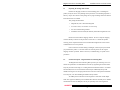
Magnum 500-Series Switching Hubs Corporate Headquarters Garrett Communications 213 Hammond Avenue Fremont, CA 94539 Phone (510) 438-9071 FAX (510) 438-9072 Magnum 500-series Switching Hub GARRETT PWR 10Mb LK/RX FDX UPLINK 1 2 3 4 5 6 7 8 Website: http://www.garrettcom.com Email: [email protected] Magnum 500-series Switching Hub GARRETT PWR AUTO FDX LK/RX 10Mb LK/RX 100 FDX UPLINK 100 10 10 F/H 1 F/H 2 1 2 3 4 5 6 7 8 Magnum 500-series Switching Hub GARRETT PWR 10Mb AUTO LK RX F H LINK 100 Mb TX 100 RX RX F H UPLINK LK 10 RX F/H F/H 1 2 3 4 5 6 7 8 With Fiber Port Magnum 500-series Switching Hub GARRETT PWR 10Mb AUTO LK F H LINK 100 Mb RX TX 100 RX RX F H UPLINK LK 10 RX F/H F/H 1 2 3 4 5 6 7 8 Installation and User Guide GARRETT GARRETT Magnum 500-Series Switching Hubs Installation and User Guide (08/98) Magnum 500-Series Switching Hubs Installation and User Guide Part #: 84-00059 Trademarks UL is a registered trademark of Underwriters Laboratories Ethernet is a trademark of Xerox Corporation UL is a registered trademark of Underwriters Laboratories Personal Hub is a registered trademark of Garrett Communications, Inc. Magnum is a trademark of Garrett Communications, Inc. Important: Magnum 500-Series Switching Hubs contain no user serviceable parts. Attempted service by unauthorized personnel shall render any and all warranties null and void. If problems are experienced with a Magnum Switching Hub, consult Section 5, Troubleshooting, of this User Guide. 1998 Garrett Communications, Inc. All rights reserved. No part of this publication may be reproduced without prior written permission from Garrett Communications, Inc. Printed in the United States of America. GARRETT i Magnum 500-Series Switching Hubs Installation and User Guide (08/98) Contacting Garrett Communications Please use the following mailing address, phone and fax numbers or Internet address. Garrett Communications 213 Hammond Avenue Fremont, CA 94539 Phone (510) 438-9071 Fax (510) 438-9072] Website: http://www.garrettcom.com email: [email protected] Federal Communications Commission Radio Frequency Interference Statement This equipment generates, uses and can radiate frequency energy and if not installed and used properly, that is in strict accordance with the manufacturer's instructions, may cause interference to radio communication. It has been tested and found to comply with the limits for a Class A computing device in accordance with the specifications in Subpart J of Part 15 of FCC rules, which are designed to provide reasonable protection against such interference when operated in a commercial environment. Operation of this equipment in a residential area is likely to cause interference, in which case the user at his own expense will be required to take whatever measures may be required to correct the interference. GARRETT ii Magnum 500-Series Switching Hubs Installation and User Guide (08/98) TABLE OF CONTENTS Page 1.0 SPECIFICATIONS .................................................................................... 1 1.1 Technical Specifications ................................................................................. 1 1.2 Ordering Information ...................................................................................... 3 2.0 INTRODUCTION...................................................................................... 4 2.1 Inspecting the Package and Product ............................................................... 4 2.2 Product Description - Magnum 500-Series Switching Hubs ......................... 4 2.2.1 Magnum 500-Series chassis................................................................ 4 2.2.2 10 & 100Mb ports, full- or half-duplex and auto-negotiation modes . 6 2.2.3100Mb Fiber port, STor SC type(single mode or multi mode) 7 2.2.4 Frame Buffering and Latency............................................................. 7 2.3 Features and Benefits...................................................................................... 9 2.4 Applications.................................................................................................. 10 3.0 INSTALLATION..................................................................................... 11 3.1 Locating the Magnum 500-Series Switching Hubs....................................... 11 3.1.1 Table-top or shelf mounting................................................................ 11 3.1.2 Wall (or Vertical) mounting................................................................ 12 3.1.3 Optional E-Stand ............................................................................... 12 3.2 Powering the Magnum 500-Series Switching Hubs ..................................... 13 3.3 Connecting Ethernet Media ………………………………………………...17 3.3.1 Connecting Twisted Pair (RJ-45, Cat 3, 5, UTP, STP) ...................... 17 3.3.2 Connecting Fiber Optic 100BASE-FX,Type ST & SC………18 3.4 Internal jumper settings for 100Mb ports, auto-negotiation ON or OFF ...... 18 4.0 OPERATION ........................................................................................... 19 4.1 Switching Funtionality, Filtering and Forwarding, Address learning ........... 20 4.2 Status LEDs .................................................................................................. 21 4.3 Manual switches for Up-link and Full/Half Duplex...................................... 21 4.4 Auto-negotiation option for copper Fast Ethernet ports .............................. 22 4.5 Auto-negotiation for 10Mb ports, half- or full-duplex mode ..................... 23 4.6 Collision-based Flow Control…………………………………….. 24 5.0 TROUBLESHOOTING ........................................................................... 25 5.1 Before Calling for Assistance ....................................................................... 26 5.2 When Calling for Assistance......................................................................... 27 5.3 Return Material Authorization (RMA) Procedure ........................................ 28 5.4 Shipping and Packaging Information............................................................ 28 APPENDIX A: WARRANTY INFORMATION ....................................................... 29 APPENDIX B : OPTIONAL 48V-DC POWER ADDENDUM .............................. 29 GARRETT iii Magnum 500-Series Switching Hubs Installation and User Guide (07/98) MAGNUM ETHERNET CONNECTIVITY PRODUCTS "DESIGNED AND MANUFACTURED IN THE USA" Overview Garrett Communications offers the Magnum line of Ethernet LAN physical layer connectivity products with industry-standard functionality. Magnum products are available worldwide through OEMs, integrators, representatives, and international distributors. Dual Speed 8-port and 16-port Stackables, 10/100 auto-sensing Stackable Hubs, SNMP Optional 10Mb series and 100Mb series, both with optional port modules Switching Hubs, unmanaged 500-Series and managed 5000-Series Two-Port Switches 100Mb RJ-45port + 10 / 100Mb combo port, or +FDX fiber port Workgroup Hubs 10Mb series and 100Mb series, both with optional port modules Personal Hubs , 100Mb 8- and 4-port with up-link, 6-port with one switched 10/100Mb Personal Hubs, 10Mb series 8-port + AUI, stackable to 5 high, + optional BNC of fiber port 8 or 9-port and 4 or 5-Port Personal Hubs, w/ man. up-link sw. Media Converters, 10Mb and 100Mb series All media combinations, incl. fiber ST, SC, mm., single mode The “X-line” of configurable MiXed Media products: Stackable Concentrators, SNMP optional, 13-Ports Mini-Concentrators, 7 Ports, Repeaters, 2-Ports Repeater Port Modules (RPMs), 6 types for Ethernet media Bridge Port Modules (BPMs), 4 types, for segment isolation Workgroup Bridges, 10Mb series Local segmentation for all media types Fan-Outs, 10Mb series 2, 4 and 8 Port Models Transceivers, 10Mb and 100Mb series 10Mb Mini-Transceivers and Coax Models, All Types 100Mb MII-TX and MII-FX models Aug. ‘98 GARRETT i Magnum 500-Series Switching Hubs 1.0 SPECIFICATIONS 1.1 Technical Specifications Installation and User Guide (08/98) Performance Aggregate Filtering Rate: 119,040 frames per second, 8 ports 297,600 frames per second, 2 TX ports (for Magnum 528 Fast Ethernet ports) Aggregate Forwarding Rate: 59,520 frames per second, 4 port-pairs 148,800 frames per second, 2 TX-pair (for Magnum 528 Fast Ethernet ports) Data Rate: 10 Mbps and 100 Mbps Address Table Capacity: 2K (1954) node addresses Buffer Size : 1 MB Latency: 5 µs + packet time (100BASE-TX to 100BASE-T) 15 µs + packet time (10BASE-T to 10BASE-T, and 10BASE-T to 100 BASE-TX/FX) Network Standards Ethernet V1.0/V2.0 IEEE 802.3: 10BASE-T, IEEE 802.3u: 100BASE-TX, 100BASE-FX Maximum Ethernet Segment Lengths Unshielded twisted pair - 100 m (328 ft) Shielded twisted pair - 150 m (492 ft) Maximum Standard Fast Ethernet Segment Lengths: 100BASE-TX (twisted pair): 100BASE-FX Fiber half-duplex: (multi-mode) 100BASE-FX Fiber full-duplex: (multi-mode) 100BASE-FX Fiber half-duplex: (single-mode) 100BASE-FX Fiber full-duplex: (single-mode) 100 m (328 ft) 412 m (1350 ft) 2.0 km (6,562 ft) 412 m (1350 ft) 15 km (49,215 ft) Connectors for copper wiring 8 Twisted Pair @ 10Mb : RJ-45 shielded, female, front mounted 2 Twisted Pair @ 100Mb) : RJ-45 shielded, female, front mounted (for Magnum 528 Fast Ethernet copper ports, normally use Cat 5 cable) Fiber Multi-mode Connector types: Fiber Port, SC-type (snap-in): Fiber optic multi-mode, 100BASE-FX Fiber Port, ST-type (twist-lock): Fiber optic multi-mode, 100BASE-FX Fiber Single-mode Connector types: Fiber Port, SC- and ST-types: Fiber optic single-mode, 100BASE-FX Manual Switches Up-link Switch: For 10Mb port-8 (10BASE-T) Full / Half duplex manual switch: Two switches, one for each 100Mb port (for Magnum 528 and 528F Fast Ethernet ports only) GARRETT 1 Magnum 500-Series Switching Hubs Installation and User Guide (08/98) Fiber Optic Interface 100Mb/s Single-mode Port Optical Typical Worst Wavelength 1300nm ----Transmitter output power -11.5dBm -15.5dBm Receiver sensitivity -32dBm ---Fiber Optic cable type 9/125µm single-mode Saturation -8dBm Max. Distance 15Km full-duplex (412m HDX, PDV limit) 100Mb/s Multi-mode Port Optical Wavelength Transmitter output power Receiver sensitivity Fiber Optic cable type Saturation Max. Distance Typical Worst 1300nm -----16.5dBm -19.5dBm -23.5dBm -32.5dBm 62.5/125µm multi-mode -14dBm 2Km full-duplex (412m HDX, PDV limit) LEDs: PWR (AC power), LK/RX (per-port Link & Receive), FDX (per-port full / half-duplex mode for 10Mb ports) For Model 528 Fast Ethernet copper ports only: AUTO (Auto-negotiation operation), per-port, 100 (ON for 100Mb/s speed), 10 (ON for 10Mb/s speed), F/H (Full- or Half-Duplex, ON for full-duplex, OFF for half-duplex). No AUTO for Model 528F Fiber ports Operating Environment Ambient Temperature: 32° to 120° F (0° to 50°C) Storage Temperature: -20°to 60°C Ambient Relative Humidity: 10% to 95% (non-condensing) Packaging Enclosure: High strength metal. Suitable for wiring closet shelf, desktop, or vertical / wall mounting (brackets included) Dimensions: 9.55 in D x 8.5 in W x 1.3 in H (24 cm x 22cm x 3.3 cm) Weight: 2.5 lb. (1.15 Kg) Cooling method: Fan cooled, @ 9 cfm Power Supply (Internal) AC Power Connector: IEC-type, male recessed, rear of chassis Input Voltage: 90 to 260 VAC (auto-ranging) Input Frequency: 47 to 63 Hz (auto-ranging) Power Consumption: 10 watts typical, 20 watts P.S. rating Agency Approvals UL listed (UL1950), cUL, CE Emissions meet FCC Part 15 Class A Warranty Three years, return to factory Made in USA GARRETT 2 Magnum 500-Series Switching Hubs 1.2 Installation and User Guide (08/98) Ordering Information Magnum 500-Series Switching Hubs MODEL DESCRIPTION Magnum 528 Switching Hub, eight ports at 10Mb F/H plus two 100Mb Fast Ethernet ports (F/H and 10/100). Self-learning 2K node-capacity address table, Store and Forward operation to filter all errored frames, full wire-speed filtering and forwarding among all ports. Up-link switch on 10Mb port # 8. Internal auto-ranging power supply. (The copper Fast Ethernet ports can be manually set to the desired mode, or may optionally be set for support of 10/100 and F/H IEEE 802.3u standard auto-negotiation). Magnum 528F-SC Same as Model 528, but with a 100BASE-FX fiber port, multi-mode SC connector, and a 100Mb RJ-45 port. Magnum 528F-ST Same as Model 528, but with a 100BASE-FX fiber port, multi-mode ST connector, and a 100Mb RJ-45 port. Magnum 528F-SMSC Same as Model 528, but with a 100BASE-FX fiber port, single-mode SC connector, and a 100Mb RJ-45 port. Magnum 528F-SMST Same as Model 528, but with a 100BASE-FX fiber port, single-mode ST connector, and a 100Mb RJ-45 port. Magnum 508 . Same as Model 528 but without the 2 Fast Ethernet ports Eight 10Mb switched ports (no 100Mb ports) Garrett Communications reserves the right to change specifications, performance characteristics and/or model offerings without notice. GARRETT 3 Magnum 500-Series Switching Hubs Installation and User Guide (08/98) 2.0 INTRODUCTION 2.1 Inspecting the Package and Product Examine the shipping container for obvious damage prior to installing this product; notify the carrier of any damage which you believe occurred during shipment or delivery. Inspect the contents of this package for any signs of damage and ensure that the items listed below are included. This package should contain: 1 Magnum 508, 528 or 528F Switching Hub 1 AC Power Cord (U.S. and other 115 VAC only) 1 Set of two wall-mounting brackets 1 Installation and User Guide (this manual), and Product Registration Card Remove the items from the shipping container. Be sure to keep the shipping container should you need to re-ship the unit at a later date. To validate the product warranty, please complete and return the enclosed Product Registration Card to Garrett Communications as soon as possible. In the event there are items missing or damaged, contact the party from whom you purchased the product. If the unit needs to be returned, please use the original shipping container if possible. Refer to Section 5, Troubleshooting, for specific return procedures. 2.2 Product Description - Magnum 500-Series Switching Hubs The Magnum 500-Series Switching Hubs provide 8-port switching services to enhance the performance of 10Mb Ethernet networks by segmenting the network traffic. They may be used with existing Cat 3 cabling and shared 10b Ethernet hubs. On models 528 and 528F, there are two Fast Ethernet switched ports additionally that provide 100Mb switching services for high speed network connections. Full speed is maintained across all ports, even when handling the smallest 64-byte frames. All 10Mb ports in both units can auto-negotiate to either half- or full-duplex mode. The copper Fast Ethernet ports on Model 528 & 528F are normally set for 100Mb with manual selection of F/H duplex, but may be optionally set for auto-negotiation. GARRETT 4 Magnum 500-Series Switching Hubs Installation and User Guide (08/98) Designed for use in departments with multiple workgroups, in remote offices and in network traffic centers, the Magnum 500-Series switches are easy to install and use. Addresses of attached nodes are automatically learned and maintained, adapting the switching services to network changes and expansions. The Magnum 500s provide high performance plug-and-play operation in a compact package. 2.2.1 Magnum 500-Series chassis Magnum 500-series Switching Hub GARRETT Magnum 500-series Switching Hub PWR AUTO LK /RX 10Mb LK /RX FDX FDX GARRETT 100 10Mb LK /RX 10 FDX F/H 1 UPLINK 1 2 3 UPLINK 100 10 PWR 4 5 6 7 F/H 2 1 2 3 4 5 6 7 8 8 Magnum 500-series Switching Hub M agnu m 50 0-series Switching Hub GARRETT GA RR ETT PWR PW R RX 100 10 F/H F H L IN K 100 Mb TX 10Mb AUTO LK 10M b AUT O LK RX RX 100 Mb TX RX LINK RX UPLINK RX F H 100 10 UPL IN K LK RX F/H F/H 1 2 3 4 5 6 7 F H F H LK RX F/H 1 8 2 3 4 5 6 7 8 Figure 2.2a: Front view Magnum 508, 528 and 528F Switching Hubs Magnum 500-Series switching hubs are equipped with eight shielded RJ-45 ports for shielded and unshielded 10BASE-T connections. Magnum 528 switching hubs also have two shielded RJ-45 Fast Ethernet ports for 100BASE-TX connection. Both units include a up-link switch for crossover connection located next to 10Mb Port # 8. Each 10Mb RJ-45 connector has two LED’s, one to indicate LK/RX (LINK / Receive) activity and the other (FDX) for indicating full-duplex mode. On Magnum 528 and 528F models, the 100Mb activity LEDs and the LINK LEDs are located in the copper Fast Ethernet ports. Other LEDs indicate when autonegotiation (copper only) is internally selected, that operating speed is 10Mb or 100Mb, and when the operating mode is full-duplex. Magnum 528 and 528F models also have two full/half (F/H) switches for the two 100Mb ports for manual selection of the full- or half-duplex mode when auto-negotiation is not selected. All connectors, switches and LED’s are located on the front panel, with the AC power connector located at the rear. Figure 2.2b: Rear view GARRETT -- Magnum 508, 528 and 528F Switching Hub 115-230V~ 50/60 Hz GARRETT 5 Magnum 500-Series Switching Hubs 2.2.2 Installation and User Guide (08/98) 10 and 100Mb ports, full- or half-duplex and auto-negotiation modes PWR AUTO LK/RX LK PWR 100 Mb RX TX FDX RX AUTO 10Mb LK/RX FDX UPLINK 100 100 10 F/H 100 RX 10 1 2 LK 10 F/H F/H F/H F H F H 1 2 3 4 5 6 7 8 Figure 2.2.2: two@100Mb copper ports (528 model), 1@100Mb copper and 1@100Mb fiber ports (528F models), and 8@10Mb ports All Magnum 500-Series Switching Hubs provide eight 10Mb switched ports. All 10Mb switched ports are independently auto-negotiating for selecting to operate in full-duplex mode, and will independently default to half-duplex mode when the 10Mb device at the other end is half-duplex or is not an auto-negotiating device. The two Fast Ethernet switched ports on the Magnum 528 and 528F normally are set (by factory default) to operate at fixed 100Mb speed for guaranteed high-speed performance. In this case, each of these two ports will run at 100Mbps at all times. The user may select full- or half-duplex mode per-port with a manual switch for flexibility to adapt to any type of Fast Ethernet devices. The Full / Half-duplex manual switches are located on the front panel next to their corresponding Fast Ethernet ports. For operation in Fast Ethernet auto-negotiating mode (copper only), internal jumpers must be set. The “AUTO” LED will then be lit to show that auto-negotiation is in operation. See Sections 4.4 and 3.4 for additional details. On Magnum 528 units, there are three LED’s for each Fast Ethernet port. One indicates operation at 100Mb speed when lit, one indicates operation at 10Mb speed when lit (possible when auto-negotiation is enabled only, copper ports), and one is lit to indicate full-duplex operation (when it is OFF, operation is half-duplex). A twisted pair or fiber cable must be connected to each 100Mb port and a proper link (LK lit) must be made with the device at the other end of the cable in order for these LEDs to provide valid indications of operating conditions. GARRETT 6 Magnum 500-Series Switching Hubs Installation and User Guide (08/98) 2.2.3 100Mb/s Fiber Port, ST or SC type (Single-Mode or Multi-Mode) 100Mb1@ LK PWR 100 M b RX TX AUTO 100 M b RX TX LK PWR RX AUTO RX 100 LK 10 100 RX F/H LK 10 F/H RX F/H F/H F H F F H H SC Connector (Magnum 528F-SC) ST Connector (Magnum 528F-ST) 1 @ 100Mb Fiber port, type ST or SC (Magnum 528F models only) The two Fast Ethernet switched ports on the Magnum 528F normally are set (by factory default) to operate at fixed 100Mb speed for guaranteed high-speed performance. The 528F’s fiber ports can be connected using a multi-mode ST, SC or single-mode ST, SC connector. In the factory-default setting, each of the 100Mb RJ-45 ports and/or the 100Mb Fiber port will run at 100Mb/s speed at all times On the Magnum 528 and 528F models, the user may select full- or half-duplex mode per-port with a manual switch for flexibility to adapt to any type of Fast Ethernet devices. The Full/Half-duplex manual switches are located on the front panel under the corresponding Fast Ethernet ports for convenient access. On Magnum 528F units, there are three LED’s per Fiber Optic port. One (LK) indicates ready for operation at 100Mb when lit, one indicates operation in full-duplex mode when ON (when it is OFF, operation is half-duplex), and one indicates Receiving Activity (RX). A fiber cable must be connected to each 100Mb port and a proper link (LK lit) must be made with the device at the other end of the cable in order for these LEDs to provide valid indications of operating conditions. 2.2.3 Frame Buffering and Latency The Magnum 500-Series are store-and-forward switches. Each frame (or packet) is loaded into the Magnum 500’s memory and inspected before forwarding can occur. This technique ensures that all forwarded frames are of a valid length and have the correct CRC, i.e., are good packets. This eliminates the propagation of bad packets, enabling all of the available bandwidth to be used for valid information. While other switching technologies such as "cut-through" or "express" impose minimal frame latency, they will also permit bad frames to propagate out to the Ethernet segments connected. The "cut-through" technique permits collision fragment frames, which are a result of late collisions, to be forwarded to add to the network traffic. Since GARRETT 7 Magnum 500-Series Switching Hubs Installation and User Guide (08/98) there is no way to filter frames with a bad CRC (the entire frame must be present in order for CRC to be calculated), the result of indiscriminate cut-through forwarding is greater traffic congestion, especially at peak activity. Since collisions and bad packets are more likely when traffic is heavy, the result of the Magnum 500’s Store and Forward operation is that more bandwidth is available for good packets when the traffic load is greatest. To minimize the possibility of dropping frames on congested ports, the Magnum 500-Series dynamically allocates buffer space from a 1 MB memory pool, ensuring that heavily used ports receive very large buffer space for packet storage. (Many other switching hubs have their packet buffer storage space divided evenly across all ports, resulting in a small, fixed number of packets to be stored per port. When the port buffer fills up, dropped packets result.) This dynamic buffer allocation provides the capability for the maximum resources of the Magnum 500 unit to be applied to all traffic loads, even when the traffic activity is unbalanced across the ports. Since the traffic on an operating network is constantly varying in packet density per port and in aggregate density, the Magnum 500 Switches are constantly adapting internally to provide maximum network performance with the least dropped packets. Another feature implemented in Magnum 500-series switches is a collisionbased flow-control mechanism. When the switch detects that its free buffer queue space is low, the switch prevents more frames from entering by forcing a collision on all receiving half-duplex ports in order to stop incoming traffic. See Section 4.6 for additional details. The latency (the time the frame spends in the switch before it is sent along or forwarded to its destination) of the 500-Series switches varies with the port-speed types, and the length of the frame is a variable here as it is with all store-and-forward switches. For 10Mb-to-10Mb or 10Mb-to-100Mb or 100Mb-to-10Mb forwarding, the latency is 15 microseconds plus the packet time at 10Mb. For 100Mb-to-100Mb forwarding, the latency is 5 microseconds plus the packet time at 100Mb. GARRETT 8 Magnum 500-Series Switching Hubs 2.3 Installation and User Guide (08/98) Features and Benefits ! Ideal for enhancing the performance of existing 10Mb segments The Magnum 508 has eight 10Mb switched ports, each operating at full-or half-duplex, for segmenting a 10Mb network to increase performance. ! Full-duplex or Half-duplex operation, auto-sensing All 10Mb and 100Mb RJ-45 ports are capable of half- or full-duplex. The Magnum 528F’s 100Mb fiber port may be used in full-duplex fiber segments for distances up to 2Km multi-mode or 15Km single-mode. ! High Performance Magnum 500-Series Switching Hubs overcome congestion on sharedbandwidth networks, performing high speed filter/forward operations on the traffic, giving each port’s segment a full 10Mb or 100Mb bandwidth. ! Assured 100Mb performance in any network set-up The two 100Mb ports normally are set to operate at 100Mb speed, and are user selected for full-or half-duplex. The 100Mb speed is assured, no matter what types of devices are attached. (Auto-negotiation is optional). ! Dynamic Buffer Space Allocation Magnum 500-Series Switching Hubs adapt to their network’s traffic changes, dynamically allocating internal resources to maximize performance even for unbalanced loads. And, flow control is included. ! Plug-and-Play installation for high performance switching Magnum 500’s are self-learning for up to 8000 node addresses, so they can be placed in operation without complex set-up procedures, even in large networks. Front-mounted LINK LEDs provide a very simple way to verify wiring connections at both ends of each attached twisted-pair cable. Front-mounted LEDs show the operating mode and activity on each port. ! Small package for office networks, "Universal" Power Supply The compact package of the Magnum 500-Series switches allow them to be used in office networks where a large rack-mount unit would be undesirable. An internal auto-ranging AC power supply allows any Magnum 500-Series Switching Hub to be used throughout the world. ! Front-mounted LEDs display operating status Front panel LED’s display the status of each port for easy monitoring. GARRETT 9 Magnum 500-Series Switching Hubs 2.4 Installation and User Guide (08/98) Applications Magnum 500-Series Switching Hubs offer a great deal of performance and flexibility, and are easily used in a variety of ways including client/server applications, departmental networks performance upgrades and collapsed backbone applications. Example 1 : Magnum 508 In a typical 10Mb network performance upgrade, multiple cascaded 10Mb hubs connect all networked devices using one 10Mb traffic domain. The Magnum 508 Switching Hub provides eight 10Mb traffic domains for increased performance. It connects all 10Mb equipment, hubs and servers, in the existing network while providing full 10Mb bandwidth to the network segment on each separate port. The Magnum 508 switch filters and forwards packets from one segment to another, containing the local traffic and allowing only the packets which need to be forwarded to go outside to the appropriate other segments. This provides several 10Mb traffic domains rather than only one as before, greatly increasing performance. This is ideal for a central departmental switch that has branches out to workgroup and/or Personal Hubs with users attached, and provides dedicated 10Mb ports for commonly used servers. Figure 2.4 illustrates this example. Figure 2.4a: BEFORE Existing 10Mb cascaded network 1 Ma gnum 80 0 E Work gr oup H ub 2 3 5 PW R C OL 6 7 L IN K RX 100 Mb/s L IN K RX Ma gnum 80 0 E Work gr oup H ub GARRETT 1 2 3 5 PW R C OL 6 7 L IN K RX 100 Mb/s L IN K RX GARRETT Congested 10Mb Network Fig. 2.4b: AFTER Magnum 508 Switching Hub provides connectivity while maintaining full 10Mbps bandwidth on each segment. PWR 10Mb RX L INK U PLINK 1 Ma gnu m 80 0E Work gr oup Hub 100 Mb/ s 1 PWR C OL 2 3 5 LINK RX 6 2 3 4 5 6 7 8 Ma gnu m 80 0E Work gr oup Hub 7 LINK RX 100 Mb/ s GARRE TT GARRE TT 10Mb Workgroups GARRETT 10 1 PWR C OL 2 3 5 LINK RX 6 7 LINK RX Magnum 500-Series Switching Hubs Installation and User Guide (08/98) Example 2 : Magnum 528 The Magnum 528 Switching Hub is a Magnum 508 plus two 100Mb Fast Ethernet RJ-45 ports. The applications may be similar to the Magnum 508 but, but with two 100Mb copper ports, it also provides switched connectivity between 10Mb and 100Mb network segments. Consider Figure 2.4c. In this example, a small corporation reached a point where it needed to make a decision about adding some 100Mb servers and users to the existing 10Mb network. The servers had installed 10/100 network interface (NIC) cards and, as one application alternative, they may be connected to the Magnum 528’s 100Mb ports to provide much better 100Mb server access speed for all the 10Mb users. As the network expands further, some users may need to go to 100Mb speed. To accommodate this while maintaining the rest of the network topology, a 100Mb hub may be attached to one of the Magnum 528’s Fast Ethernet port (see illustration in Figure 2.4c below, showing only one server per 100Mb port). The Fast Ethernet hub (for example, a Magnum Lite ML8 100Mb office hub) then provides 100Mb ports for the servers and for some 100Mb users. The Magnum 528 Switching Hub provides complete network connectivity so that all 10Mb and 100Mb nodes operate in a unified manner, functioning as one plugand-play switched network facility. In this example, the 10Mb segments on the 528’s 10Mb ports each have 10Mb of switched bandwidth, and may be either half- or full-duplex per port. Simultaneously, the two Fast Ethernet ports provide 100Mb F/H each, and have full-speed switched access to each other as well as to each of the 10Mb ports. PWR LINK RX AUTO LINK 10Mb RX UPLINK 1 2 1 2 3 4 5 6 7 8 10Base-T Mag num 800E Wor kgrou p Hub 10 0 Mb/s GARR ETT 100Mb Server, PCs PWR COL 1 4 2 3 LI NK RX 5 8 6 7 LI NK RX 10Mb Workgroup 100Mb Servers Figure 2.4c: Using a Magnum 528 Switch, 100Mb servers and users are added to an existing 10Mb network GARRETT 11 Magnum 500-Series Switching Hubs Installation and User Guide (08/98) Example 3 : Magnum 528 In another situation similar to Example 2 above, the network may need to be linked to a Fast Ethernet backbone. This application is handled by the Magnum 528 using one 100Mb switched port for local high speed servers and users, while using the other 100Mb switched port for a link upstream. Using two Magnum 528s and linking a 100Mb switched port from each unit, one can implement a Fast Ethernet switched connection which can run in full duplex mode. The result is similar to “stacking” the two Magnum 528s to provide a net total 16 ports of switched 10Mb plus 2 ports of switched 100Mb. When using a Magnum 528’s 100Mb switched port as a link, it is frequently desirable to make the connection to the upstream device using fiber cable operating at 100Mb speed. In this situation, an external 100Mb Media Converter unit (such as a Magnum 15E) is used to change from twisted pair cable to fiber cable. Because commercially-available 100Mb Media Converters do not support 10/100 speed auto-negotiation, it is necessary in this situation to operate both ends of the fiber link with ports that have fixed 100Mb-speed capability. In addition, since 100Mb fiber cable has severe distance limitations at half-duplex, it is almost always necessary to operate such a fiber link in the full-duplex mode. Many low-end switching hubs that only have auto-negotiation on their 100Mb ports cannot support this application, but the Magnum 528 . . . with fixed 100Mb speed as a default setting, and with manuallyselected half- or full-duplex mode per Fast Ethernet port . . . handles this readily. 100Mb Hub 1 2 3 4 5 6 7 8 PWR LINK RX AUTO LINK 10Mb RX UPLINK 1 2 1 2 3 4 5 6 7 Internet 8 10Base-T Ma gnum 800 E Wor kgr oup Hub 100 Mb/s 2 3 5 L INK RX 6 7 L INK RX nu C onm 15 ve E rter PW R 100 Mb /s LIN K M M ag ed ia 1 PWR COL GARRET T GA RR ETT LIN K 100Mb Servers and Workstations Router 100Mb Fiber Link 100Mb Media Converter 10Mb Workgroup Figure 2.4d: The Magnum 528 provides 100Mb ports for backbone connections. GARRETT 12 Magnum 500-Series Switching Hubs Installation and User Guide (08/98) Example 4 : Magnum 528F In another situation similar to Example 3 above, the network may need to be linked with fiber cabling to a Fast Ethernet backbone. This application is handled by the Magnum 528F, using one 100Mb switched copper port for local high speed servers and users, while using the fiber 100Mb switched port for the fiber backbone connection. Using the Magnum 528F’s 100Mb switched fiber port, one can implement a Fast Ethernet switched fiber connection that runs in full-duplex mode. The result is a high-speed LAN connection upstream with switched 100Mb full-duplex performance and maximum fiber distance – all without a 100Mb media converter. Alternatively, two Magnum 528Fs can be connected with switched 100Mb fiber to form a larger LAN. When using a Magnum 528F’s 100Mb switched fiber port as a link, it is frequently desirable to operate the connection to the upstream device in full-duplex mode since 100Mb fiber cable has severe distance limitations at half-duplex. In this situation, it is necessary to operate both ends of the fiber link with ports that have fixed 100Mb-speed and user-determined full-duplex capability (no auto-negotiation). Many low-end “commodity” switching hubs that only have RJ-45 ports with auto-negotiation cannot support this application. They have no built-in fiber, and they do not properly support 100Mb media converters. Even if they did support media converters properly, the converters are awkward extra items that add substantially to the cost. But the Magnum 528F models . . . with fixed 100Mb speed as a default setting on the Fast Ethernet ports, and with manually-selected half- or full-duplex mode per Fast Ethernet port . . . handle this application readily and economically. 100Mb Hub Magnum 500-series Switching Hub GARRETT 1 2 3 4 5 6 7 8 PW R LK TX 100 10 F H 10Mb AUTO LINK 100 Mb RX RX RX F F/H H UPLINK LK RX Internet F/H 1 2 3 4 5 6 7 8 10Base-T 100Mb Fiber Link 100Mb Servers and Workstations 100Mb Media Converter Magn um 800E Workgrou p Hub 10 0 Mb/ s PWR COL Router 1 4 2 3 LI NK RX 5 8 6 7 LI NK RX GA RRETT 10Mb Workgroup Figure 2.4e: The Magnum 528F provides a 100Mb port for backbone connection. GARRETT 13 Magnum 500-Series Switching Hubs 3.0 Installation and User Guide (08/98) INSTALLATION This chapter provides instructions for installing Magnum 500-Series switches. 3.1 Locating Magnum 500-Series switches The location of a Magnum 500-Series switch is dependent on the physical layout of the network. Typically the switch is placed where combinations of 10Mb and 100Mb network devices need to be connected to communicate with each other. The compact size of the unit allows it to be conveniently placed in an office or lab area, and it can also be either shelf of wall-mounted (see instructions in 3.1.2 below). Wallmounting brackets are included, usable for single units (but not for stacks). Locate an AC receptacle that is within six feet (2 meters) of the intended Magnum 500 site. The rugged metal case of the Magnum 500 will normally protect it from accidental damage in a lab or workplace setting. Maintain an open view of the front to visually monitor the status LEDs. Keep an open area around the unit so that cooling can occur from the small fan in the bottom-rear while the unit is in operation. See figure below. GARRETT 115-230V~ 50/60 Hz FAN EXHAUST Figure 3.1 : Location of Magnum 500’s cooling fan exhaust 3.1.1 Table-Top or Shelf Mounting The Magnum 500-Series switch can be easily mounted on a table-top or any suitable horizontal surface, and has four rubber feet to provide stability without scratching finished surfaces. When stacked, the rubber feet also provide separation between units for the exhaust of the rear cooling fan. GARRETT 14 Magnum 500-Series Switching Hubs 3.1.2 Installation and User Guide (08/98) Wall (or Vertical Surface) Mounting Each Magnum 500-Series switch is shipped with two metal mounting brackets (and screws) to allow the unit to be mounted in nearly any desired orientation or position. The brackets are attached to the metal hub case using one of the metal screws for each bracket, and attached to the Magnum 500 through the round hole of the bracket. A usersupplied screw attaches the bracket to the mounting surface. It is recommended that the mounting brackets be attached to two opposite corners of the unit. When properly attached, the brackets will extend slightly below the base of the unit to allow clearance for the rubber feet and for cooling fan exhaust space. 100 Mb/s GARRETT PW R Magnum 500-series LK/RX Switching Hub F D X AU TO 1 01 00 F/ H GARRETT Proper mounting bracket attachment Magnum 500 with attached mounting brackets Figure 3.1: Magnum 500-Series, metal mounting brackets 3.1.3 Optional E-Stand The optional E-Stand provides a vertical mounting option for the Magnum 500-Series Hubs. When horizontal placement is not possible or desirable (such as on the floor in carpeted areas), the E-Stand offers a unique space management option. Simply align the rectangular cut-out on the E-Stand with the air vent on either side of the Magnum 500 unit. The E-Stand also allows the Magnum 500-Series unit to be securely mounted via two screws that connect through the E-Stand and into the side of the unit. See Figure 3.1.3, following. GARRETT 15 Installation and User Guide (08/98) 8 7 6 5 10 4 Magnum 528 Switching Hub RX U PLINK Magnum 500-Series Switching Hubs 1 LIN K AU TO RX PW R 1 0 LIN K Rectangular cut-out (Air Vent) 1 2 GARRETT 2 3 Screw holes Figure 3.1.3 : Magnum 528 mounted on E-stand 3.2 Powering the Magnum 500-Series Switch Magnum 500-Series Switching Hubs incorporate an internal universal power supply, and have a recessed male IEC connector for the AC power cord at the right-rear. A six-foot 115 VAC 60 Hz standard power cord is supplied with each unit shipped within the United States and Canada. GARRETT 115-230V~ 50/60 Hz Figure 3.2: Magnum 500-Series AC power connector The Magnum 500’s auto-ranging power supply supports installation environments where the AC voltage is from 90 to 260 volts with a power input frequency between 47 and 63 Hz. The unit will consume just under 10 watts of power typically. When connecting the Ethernet cabling, there is no need to power down the unit. Individual segments can be connected or disconnected without concern for AC power-related problems or damage to the unit. GARRETT 16 Magnum 500-Series Switching Hubs 3.3 Installation and User Guide (08/98) Connecting Ethernet Media The Magnum 500-Series Switching Hubs can be connected to the following media types: 100BASE-TX and 10BASE-T. (Magnum 508’s only have 10BASE-T ports). CAT 5 cables should be used when making 100BASE-TX connections. When the ports are used as 10BASE-T ports, CAT 3 may alternatively be used. In either case, the maximum distance for unshielded twisted pair cabling is 100 meters (328 ft). Media Twisted Pair (CAT 3) Twisted Pair (CAT 5) IEEE Standard 10BASE-T 100BASE-TX Connector RJ-45 RJ-45 NOTE : It is recommended that high quality CAT. 5 cables (which work for both 10Mb and 100Mb) be used whenever possible in order to provide flexibility in a mixed-speed network, including both 10 and 100Mb/s. PWR 10 10 1 2 1 2 3 4 5 6 7 8 F/H 100BASE-TX connections (Magnum 528 only) 3.3.1 FDX UPLINK 100 F/H 10Mb LK/RX AUTO FDX LK/RX 100 10BASE-T connections Connecting Twisted Pair (RJ-45, CAT 3 or CAT 5, Unshielded or Shielded) The following procedure describes how to connect a 10BASE-T or 100BASE-TX twisted pair segment to the RJ-45 port. The procedure is the same for both unshielded and shielded twisted pair cables. 1. 2. 3. Using standard twisted pair media, insert either end of the cable with an RJ-45 plug into the RJ-45 connector of the port. Note that, even though the connector is shielded, either unshielded or shielded cables and wiring may be used. Connect the other end of the cable to the corresponding device. Use the LINK LED to ensure proper connectivity by noting that the LED will be illuminated when the unit is powered and proper connection is established. For Port # 8, if the LINK LED is not illuminated, change the setting of the up-link switch. If this does not help, ensure that the cable is connected properly and that the device on the other end is powered and is not defective. GARRETT 17 Magnum 500-Series Switching Hubs Installation and User Guide (08/98) 3.3.2 Connecting Fiber Optic 100BASE-FX, Type ST and SC L K P WR 100 Mb RX TX RX LK PWR AUT O 100 AUTO 100 Mb RX TX RX 100 LK LK 10 10 RX F /H F H F RX F/H F /H H F/H F H 100BASE-TX connections (Magnum 528F only) The following procedure applies to 100BASE-FX applications using the Magnum 528F Switching Hub with ST-type (twist-lock) and SC-type (snap-in) fiber connectors. 1. 2. 3. 4. 5. 3.4 Before connecting the fiber optic cable, remove the protective dust caps from the tips of the connectors on the Magnum 528F. Save these dust caps for future use. Wipe and clean the ends of the dual connectors with a soft cloth or lint-free lens tissue dampened in alcohol. Make certain the connectors are clean before connecting. Note: One strand of the duplex fiber optic cable is coded using color bands at regular intervals; you must use the color-coded strand on the associated ports at each end of the fiber optic segment. Connect the Transmit (TX) port (light colored post on ST) on the Magnum 528F to the Receive (RX) port of the remote device. Begin with the color-coded strand of the cable for this first “Transmit-to-Receive” connection. Connect the Receive (RX) port (dark colored post) on the 528F to the Transmit (TX) port of the remote device. Use the non-color coded fiber strand for this. The LINK LED corresponding to the fiber port on the front of the 528F will illuminate when a proper connection has been established at both ends (and when power is ON in the unit). If LINK is not lit after cable connection, the normal cause is improper cable polarity. Swap the fiber cables on the 528F’s fiber connectors (either ST or SC type) to remedy this situation. Internal jumper settings, 100Mb RJ-45 ports, auto-negotiation ON or OFF The factory (or default) setting is for fixed 100Mb speed (no auto-negotiation) so that the speed and mode of the Model 528’s copper Fast Ethernet ports’ operation is certain, regardless of whether the attached device does or does not properly support autonegotiation. This is desirable when there are unknown devices presently or potentially connected, which may or may not operate correctly at all times with auto-negotiation. In some applications, it may be desired to use standard auto-negotiation and/or to configure the first 100Mb copper port for up-link. For trained technicians, there are internal switches and jumper settings that allow these choices to be made, as described in GARRETT 18 Magnum 500-Series Switching Hubs Installation and User Guide (08/98) Figure 3.5. Be certain that the main power is off before opening the unit or changing any internal settings. Switch SW2 SW7 Port Both 100Mb Port 1 When Non-Auto: Jumper JP4 JP3 Port Port 1 Port 2 SW7 Function Default setting Auto-negotiation 100 Mb (Non-Auto) Uplink Uplink = Function 10 / 100 config 10 / 100 config Position 1 - 2 100 Mb (default) 100 Mb (default) JP3 Position 2 - 3 10 Mb 10 Mb SW2 100 Mb PORTS NEGOTIATION 100 SW2 AUTO 1 100 Mb 1 JP3 10 JP4 100 SW7 100 Mb PORT 1 = UPLINK X 10 JP4 Manual setting AUTO Uplink X Figure 3.5 : Magnum 528’s internal jumpers for auto-negotiation ON or OFF Note that auto-negotiation is an on-going process that can introduce changes in network operation at any time, whether intended or accidental. Getting an autonegotiating network running properly once is not enough to make certain that it will continue to operate correctly indefinitely. Attached devices can and do change while the network is operating. In addition, there may be intermediate devices (such as media converters, which do not support auto-negotiation) in the cabling between the switched port and the rest of the network, requiring the switching port to be fixed in speed and mode in order to achieve and maintain the desired overall network operation. Therefore, the default setting of fixed 100Mb speed with F/H manual selection (no auto-negotiation, copper ports) is generally desirable because it is a safe and a maximum-performance condition for the Model 528’s Fast Ethernet high speed ports. See Section 4.4 for additional information on auto-negotiation functionality. 4.0 OPERATION This chapter describes the functions and operation of the Magnum 508, 528 and 528F Switching Hubs. GARRETT 19 Magnum 500-Series Switching Hubs 4.1 Installation and User Guide (08/98) Switching Functionality The Magnum Model 508 provides switched connectivity at Ethernet wire-speed among all of its eight 10Mb ports. The Magnum Model 528 and 528F switch interconnect eight 10Mb and two 100Mb segments for unified access at wire speed. Each Magnum 500-Series port is a separate traffic domain, and all ports operate to maximize bandwidth utilization and network performance. All ports can talk to all other ports in a Magnum 500, but local traffic on a port will not consume any of the bandwidth on any other port. Magnum 500-Series units are plug-and-play devices. There is no software configuring to be done at installation or for maintenance. The only hardware configuration settings are user options for UP-LINK on 10Mb port #8, and the Half / Full duplex mode selection for the 100Mb ports of the Magnum 528 and 528F. The internal functions of both are described below. Filtering and Forwarding Each time a packet arrives on one of the switched ports, the decision is taken to either filter or to forward the packet. Packets whose source and destination addresses are on the same port segment will be filtered, constraining them to one port and relieving the rest of the network from processing them. A packet whose destination address is on another port segment will be forwarded to the appropriate port, and will not be sent to the other ports where it is not needed. Traffic needed for maintaining the operation of the network (such as occasional multi-cast packets) are forwarded to all ports. The Magnum 500-Series Switching Hubs operate in the store-and-forward switching mode, which eliminates bad packets and enables peak performance to be achieved when there is heavy traffic on the network. Address Learning All Magnum 500-Series units have large address table capacity of 1.9K node addresses, suitable for use in large networks They are self-learning, so that as nodes are added or removed or moved from one segment to another, the 500s automatically keep up with node locations. To reset the address buffer, cycle power down-and-up. GARRETT 20 Magnum 500-Series Switching Hubs 4.2 Installation and User Guide (08/98) Status LEDs For all Magnum 500-series models : PWR LK/RX FDX : Power LED, ON when AC power is applied to the unit. : Link/Receive LED per 10Mb port, Steady ON for Link, Flashing when the port has Receive activity. : Full / Half Duplex LED per 10Mb port, ON when the port has auto-negotiated to operate Full Duplex, OFF for half duplex. For Magnum 528 and 528F models only : AUTO : Auto-negotiation LED, ON when copper “100Mb” ports are configured to operate in the auto-negotiation mode, OFF when their speed is internally fixed at 100Mb (no auto-negotiation, no 10Mb speed). 10 LED : One for each “100Mb” port, ON when the copper port speed is 10Mb/s. 100 LED : One for each “100Mb” port, ON when the port speed is 100Mb/s. F/H : Full / Half duplex LED, one for each 100Mb port, ON when the port is running full duplex, OFF for half duplex. 4.3 Manual switches for 10Mb Up-link, and Fast Ethernet Full / Half Duplex PWR LK PWR FDX UPLINK 100 Mb RX TX RX AUTO FDX LK/RX AUTO 100 100 LK 10 100 10 RX 10 F/H F/H 5 6 7 Up-link Switch F H F F/H H STConnector (Magnum528Fonly) 1 2 F/H F/H Switch (Magnum 528 only) Figure 4.3 : Up-link and F/H manual switches on front panel The unit has a manual Up-link switch, located on the front panel next to 10Mb Port # 8 which it controls. It enables the port’s cable to either connect to a user station node (= position) or to be cascaded (X position) to a another 10Mb repeater or switching hub in the network. Verify proper Up-link switch position by noting Port 8’s LK/RX LED status, which is illuminated when a proper link is made. (Note: for optional up-link setting on 100Mb copper port #1 via an internal switch, see Section 3.4) The two F/H switches are located next to each Fast Ethernet port on Magnum 528’s. When the two Fast Ethernet ports of a Model 528 are set to operate at fixed 100Mb speed (no auto-negotiation), manual selection of half or full duplex at 100Mb GARRETT 21 Magnum 500-Series Switching Hubs Installation and User Guide (08/98) may be made for each port separately. If the Magnum 528’s Fast Ethernet copper ports are internally set for auto-negotiation (AUTO LED is ON), then the F/H switch selection has no effect. The adjacent F/H LED will indicate the full- or half-duplex operating status of the port as determined by the internal auto-negotiation logic. 4.4 Auto-negotiation option for Fast Ethernet copper ports The Magnum 528 Switching Hub’s Fast Ethernet copper ports can be set for either fixed 100Mb speed or for 10/100 speed F/H auto-negotiation per the IEEE802.3u standard. The selection is made via an internal jumper (see Section 3.4 for jumper-setting instructions ). The factory default setting is for fixed 100Mb speed. At 100Mb-fixed speed, the user may select half- or full-duplex mode manually on each Fast Ethernet port separately. The two Full/Half duplex manual switches are located on the front panel next to their corresponding ports. See Section 4.3 above for F/H manual switch description. One frequently-used application for the Magnum 528’s Fast Ethernet ports is to connect one of them using fiber cabling to another switching hub in the network backbone, or some other remote 100Mb device. In this case, it is desirable to operate the fiber link at 100Mb speed, and at either half- or full duplex mode depending on the capabilities of the remote device. Standard commercially-available Fast Ethernet media converters do not support auto-negotiation, and require that the switched port to which they are connected be at 100Mb fixed speed. Attachment to 10/100 auto-negotiation ports will not work properly. The Magnum 528’s Fast Ethernet ports handle this situation easily in the default setting.. When the Fast Ethernet copper ports are set in the auto-negotiation mode, the F/H manual switches have no effect. The AUTO LED will be ON. The operating speed and F/H mode of the high speed ports can change at any time to adapt to (real or imagined) changes in the network. The “10” and “100” LEDs will indicate the operating speed. When Magnum 528’s Fast Ethernet copper ports are set for auto-negotiation and connected to an another auto-negotiating device, there are 4 different speed and F/H modes selectable depending on what the other device supports. These are: (1) 100Mb full-duplex, (2) 100Mb half-duplex, (3) 10Mb full-duplex and (4) 10Mb half-duplex. GARRETT 22 Magnum 500-Series Switching Hubs Installation and User Guide (08/98) The auto-negotiation logic will attempt to operate in descending order and will normally arrive at the highest order mode that both devices can support at that time. (Since autonegotiation is potentially an externally-controlled process, the original “highest order mode” result can change at any time depending on network changes that may occur). If the device at the other end is not an auto-negotiating device, the Magnum 528’s Fast Ethernet ports will try to detect its idle signal to determine 10 or 100 speed, and will default to half duplex. General information Auto-negotiation per-port for 802.3u-compliant switches occurs when: the devices at both ends of the cable are capable of operation at either 10Mb or 100Mb speed and/or in full- or half-duplex mode, and can send/receive auto-negotiation pulses, and . . . -- when the second of the two connected devices is powered up*, i.e., when LINK is established for a port, or -- when LINK is re-established on a port after being lost temporarily. • NOTE – some NIC cards only auto-negotiate when the computer system that they are in is powered up. These are exceptions to the “negotiate at LINK – enabled” rule above, but may be occasionally encountered. When operating in 100Mb half-duplex mode, cable distances and hop-counts may be limited within that collision domain. The Path Delay Values (PDV) bit-times must account for all devices and cable lengths within that domain. For Magnum 528 Fast Ethernet switched ports operating at 100Mb half-duplex, the bit time delay is 50BT. 4.5 Auto-negotiation for 10Mb ports, half- or full-duplex mode Full-duplex Ethernet provides separate Transmit and Receive data paths, enabling simultaneous bi-directional collision-free data movements on a port. The network topology must be a “star” type, not a “bus” type. With full-duplex mode, the GARRETT 23 Magnum 500-Series Switching Hubs Installation and User Guide (08/98) cable distance is only limited by the physical layer line driver and cable attenuation. There are no collision-domain restrictions or limitations. The Magnum 500-Series Switching Hubs perform half- or full-duplex mode auto-negotiation independently on all eight 10Mb switched ports. If the device or node on the other end of a port’s attached cable supports F/H mode auto-negotiation or is set to operate as full-duplex, the Magnum 500’s 10Mb port will negotiate to run full-duplex. If the attached device or node doesn’t support F/H mode auto-negotiation (for example, if it is a 10Mb repeater or a standard 10Mb hub), the Magnum 500’s 10Mb ports will default to operate at half-duplex. If needed to extend to a greater distance than the 100 meters available with twisted pair cabling, an external 10Mb fiber Media Converter unit can be used to convert the cable to fiber. Fiber cable at 10Mb can run up to 2Km with multi-mode fiber and 15Km with single-mode fiber, either half- or full-duplex. (At 100Mb speed, fiber cable can achieve these distances only in the full-duplex mode). 4.6 Collision-based Flow-control Magnum 500 series switches incorporate a collision-based flow-control mechanism. The purpose of flow-control is to reduce the risk of data loss if a long burst of activity causes the switch to backlog frames until its memory is fill up. This is most likely to occur when data is moving from a 100Mb port to a 10Mb port, and the speed difference makes the 10Mb port unable to keep up. It can also occur when multiple 10Mb ports are attempting to transmit to one 10Mb port, and in other protracted heavy traffic situations. The switch is constantly monitoring the size of the internal free-buffer queue. It detects that it is becoming congested when there are fewer than 256 buffers on the free queue(out of 1M capacity). At that time, the switch prevents frames from entering the device by forcing a collision indication on all half-duplex ports (except for the ports on which the switch is transmitting). When the switch has transmitted some of the backlog from its buffer, and the available free-buffer queue increases to more than256 spaces, forced collisions cease, and frames can again enter the switch. (The 256 buffer threshold ensures that all ports can receive and complete a maximum-length frame that may be in process. GARRETT 24 Magnum 500-Series Switching Hubs 5.0 Installation and User Guide (08/98) TROUBLESHOOTING All Magnum Ethernet products are designed to provide reliability and consistently high performance in all network environments. The installation of Magnum 508 Switching Hubs is a straightforward procedure (see Sections 3); the operation is also straightforward and is discussed in Sections 4. Should problems develop during installation or operation, this section is intended to help locate, identify and correct these types of problems. Please follow the suggestions listed below prior to contacting your supplier. However, if you are unsure of the procedures described in this section or if the Magnum 508 product is not performing as expected, do not attempt to repair the unit; instead contact your supplier for assistance or contact Garrett Communications Customer Support. 5.1 Before Calling for Assistance 1. If difficulty is encountered when installing or operating the unit, refer back to the Installation Section of the applicable chapter of this manual. Also check to make sure that the various components of the network are inter-operable. 2. Check the cables and connectors to ensure that they have been properly connected and the cables/wires have not been crimped or in some way impaired during installation. (About 90% of network downtime can be attributed to wiring and connector problems.) 3. Make sure that an AC power cord is properly attached to each Magnum 500-Series unit. Be certain that each AC power cord is plugged into a functioning electrical outlet. Use the PWR LEDs to verify each unit is receiving power. 4. If the problem is isolated to a network device other than the Magnum 500Series product, it is recommended that the problem device be replaced with a known good device. Verify whether or not the problem is corrected. If not, go to Step 5 below. If the problem is corrected, the Magnum 500-Series Switching Hub and its associated cables are functioning properly. 5. If the problem continues after completing Step 4 above, contact your supplier of the Magnum 500-Series unit (or if unknown, contact Garrett Communications) by fax, phone or email for assistance. GARRETT 25 Magnum 500-Series Switching Hubs Installation and User Guide (08/98) 5.2 When Calling for Assistance Please be prepared to provide the following information. 1. 2. 3. 4. 5.3 A complete description of the problem, including the following points: a. The nature and duration of the problem; b. Situations when the problem occurs; c. The components involved in the problem; d. Any particular application that, when used, appears to create the problem; An accurate list of Garrett Communications product model(s)involved, with serial number(s). Include the date(s) that you purchased the products from your supplier. It is useful to include other network equipment models and related hardware, including personal computers, workstations, terminals and printers; plus, the various network media types being used. A record of changes that have been made to your network configuration prior to the occurrence of the problem. Any changes to system administration procedures should all be noted in this record. Return Material Authorization (RMA) Procedure All returns for repair must be accompanied by a Return Material Authorization (RMA) number. To obtain an RMA number, contact Garrett Communications Customer Support at (510) 438-9071 (office hours: 8AM - 5PM Pacific Standard Time) or send email to [email protected]. When calling, please have the following information readily available: Name and phone number of your contact person. Your Company Name Shipping Address Product Name Serial Number (or Invoice Number) Packing List Number (or Sales Order Number) Date of installation Failure symptoms, including a description of the specific problem Garrett Communications will carefully test and evaluate all returned product. If the problem or condition cannot be duplicated, the unit will be returned as: No Problem Found. Garrett Communications reserves the right to charge for the testing of nondefective units under warranty. Testing and repair of product that is not under warranty will be charged for. GARRETT 26 Magnum 500-Series Switching Hubs 5.4 Installation and User Guide (08/98) Shipping and Packaging Information Should you need to ship the unit back to Garrett Communications, please follow these instructions: 1. Package the unit carefully. It is recommended that you use the original container if available. Units should be wrapped in a "bubble-wrap" plastic sheet or bag for shipping protection. ( You may retain all connectors and this Installation Guide.) CAUTION Do not pack the unit in Styrofoam "popcorn" type packing material. This material may cause electro-static shock damage to the unit. 2. Clearly mark the Return Material Authorization (RMA) number on the outside of the shipping container. 3. Garrett Communications is not responsible for your return shipping charges. 4. Ship the package to: Garrett Communications 213 Hammond Avenue Fremont, CA 94539 Attn.: Customer Service APPENDIX A : Warranty Information Garrett Communications warrants its products to be free from defects in materials and workmanship for a period of three (3) years from the date of shipment by Garrett Communications. During this warranty period, Garrett Communications will repair or, at its option, replace components in the products that prove to be defective at no charge other than shipping and handling, provided that the product is returned pre-paid to Garrett Communications. This warranty will not be effective if, in the opinion of Garrett Communications, the product has been damaged by misuse, misapplication, or as a result of service or modification other than by Garrett Communications. Garrett Communications reserves the right to make a charge for handling and inspecting any product returned for warranty repair which turns out not to be faulty. Please complete the warranty card as this acts as a product registration, and mail it to Garrett Communications within two weeks of your purchase. GARRETT 27 Magnum 500-Series Switching Hubs Installation and User Guide (08/98) APPENDIX B : 48VDC ADDENDUM B1.0 SPECIFICATIONS - MAGNUM 508, 528 and 528F 48VDC OPTION Power Supply (Internal -48 VDC) DC Power Connector: 3 terminals: “-“, “GND”, “+” Input Voltage: 36 - 72 VDC (auto-ranging) Output Power: 40 watts, max. Power Consumption : 20 watts max. With the exception of the power supply, all specifications for the Magnum 500series with 48VDC power options are identical to those listed in Section 1. B2.0 MAGNUM 508, 528 AND 528F (48VDC OPTION) The internal 48VDC power supply models are designed for installations where a battery plant is the power source. The operational range for the 48 VDC power supply is 36 - 72 VDC. Each unit is normally convection-cooled for silent operation. The functionality of the Magnum 500-series with 48VDC power options is identical to the standard 508, 528 and 528F models. B3.0 APPLICATIONS Magnum 508-48VDC and 528-48VDC Switching Hubs are easily installed in a variety of applications where 48 VDC power is used as the primary power source. The 48VDC power configuration provides an Ethernet networking solution utilizing a special power supply in hubs with a proven track record. The solution is particularly useful in the telecommunication industry, where it is common for equipment to operate on -48 VDC power. Such companies include regular and wireless telephone service providers, Internet service providers (ISPs) and other communications companies , as well as highavailability equipment serving broadcasters, publishers, and some financial institutions. In addition, many large newspaper operations, brokerage firms and other facilities often use a battery backup system to maintain operations in the event of a power failure, and even long term outages. The 508/528-48VDC is ideal for utility use in this type of battery-powered plant. It is frequently used to provide an Ethernet LAN connection for computer system back up, management computers and operations monitoring equipment. GARRETT 28 Magnum 500-Series Switching Hubs Installation and User Guide (08/98) B4.0 INSTALLATION This section describes the installation of the 48 VDC power terminal leads to the 48 VDC power terminal block on the Magnum 500-series switching hub. _ GND + Figure B4.1: 48 VDC Terminal Block on Magnum 508/528/528F-48VDC models 36-75VDC The 48 VDC terminal block on the Magnum 500-series is located on the rear of the unit and is equipped with three (3) screw-down lead posts. The leads are identified as negative (-), positive (+), and chassis ground (GND). The actual connection procedure is very straightforward. Simply connect the DC leads to the Magnum unit, beginning with ground. Ensure that each lead is securely tightened. B5.0 OPERATION Operation of the Magnum 508, 528 and 528F with -48VDC option is identical to that of the standard models. B6.0 TROUBLESHOOTING Please refer to Section 5.0 for troubleshooting information. GARRETT 29