1
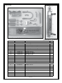
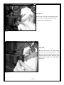
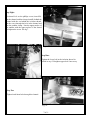
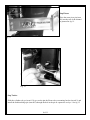
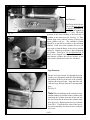
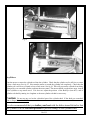
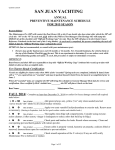
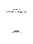
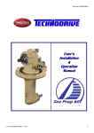
TR-1 Gold
Cylinder and Bracket
Mounting Instructions
Suzuki 9.9 & 15 HP: 1997 & Newer
Johnson/OMC 9.9 & 15 HP: 2002-2007
1
PN 906-1090-00
Parts List:
Cylinder Mounting Kit PN 120-1090-00
Cylinder Kit PN 120-0900-00
Item Number
Part Number
Name
Cylinder Mounting Kit 120-1090-00
1
330-1091-00
Standoff, Spacer
2
130-1092-00
Bracket, Rod Eye Mounting
3
330-1023-00
Pin, Stern Pivot
4
380-1094-00
Channel, Cylinder Mounting
5
340-1095-00
Clamp, Channel Snubber
12
310-0067-01
Hair Pin Cotter Lg.
13
310-0067-02
Hair Pin Cotter Med.
14
310-0076-25
LW, Split 1/4, SS
15
310-0076-31
LW,Split 8mm
16
130-0084-02
“U” Bolt 1 3/4” ID 1/4-20 with nuts
17
310-0208-12
Hex Cap screw M8 X 12mm (bolt)
19
310-2501-25
Clevis Pin 1/4 D X 1.25
20
310-0014-08
#10-32 UNF X 1/2 Phillips Pan HD screw
Cylinder Kit 120-0900-00
Qty.
2
1
1
1
1
1
1
2
2
1
2
1
1
31
33
34
35
36
330-1002-00
310-0042-09
340-0900-00
321-0001-00
330-1101-00
Rod Eye, 5/16-24
Hex Jam Nut 5/16-24
Cylinder
Fitting, Straight 1/8 NPT X 1/4
Zinc Anode (Replace)
1
1
1
2
1
37
38
40
310-0040-26
328-0901-00
328-0902-00
Washer, Flat, Nylon 1/4 ID X 3/8 OD x .03 Thick
Bushing 1/4 ID X 5/16 OD X 1/4”L
Cylinder Tail Bushing
1
2
1
of 11
Tools:
Minimum Tools Needed:
1- 13 mm Wrench
1-1/2 Wrench
1- 7/16 Wrench
1- #1 Phillips Screwdriver
1- Thread Locker (Loctite or similar)
1- 12mm Wrench
of 11
Introduction:
Caution: You are mounting this steering cylinder to a vibration isolation mount on
your motor. Note; that the factory bolts and screws have had thread locker used on
them. You must use thread locker on all threaded nuts and bolts in this installation.
Before starting installation: Loosen the friction lock on the motor. The motor must turn
freely both ways without friction, failure to do so, will cause damage to the autopilot. (It
is located on the Port side of the steering pivot tube.)
Installation of Mounting Bracket:
Step One:
Remove the upper factory nut and washer from
the lower vibration isolation shroud. See Fig 1
(Save these or use if you change motors)
Fig. 1
Step Two:
Reverse the factory bolt with it’s washer in the
hole it was removed from. Use thread lock on the
bolt thread and screw it into the stand off spacer
(item #1) and tighten. See Fig 2.
Fig. 2
of 11
Step Three:
Remove the lower nut and washer from the
lower vibration isolation shroud. See Fig 3
(keep this nut and washer also)
Fig. 3
Step Four:
Reverse the factory bolt and washer
in the hole it was removed from. Use
thread lock on bolt threads and screw it
into the stand off spacer (item #1) and
tighten finger tight. You will tighten
these later.
Fig. 4
5 of 11
Step Five:
Place the “U” Bolt (item #16) around steering
pivot tube as pictured in fig. 5.
Fig 5
Step Six:
Place the Rod eye Bracket (item # 2) over
the “U” bolt ends. Slide it up as far as it
will go against the slopped gussets. With
the lower arch against the pivot tube and the
face (with the “U” bolt through it) parallel to
the steering pivot center line. Install the lock
washers (item #14) and nuts on the legs of the
“U” bolt and tighten.
Fig 6
Step Seven:
Use thread lock on the two 8mm x 12mm bolts
(item#17) and put the bolts with lock washers
(item # 15) through the Channel (item #4) and into
the two standoffs (item #1) that were previously
mounted. Tighten finger tight. You will tighten
firmly later. See fig 6.
Fig 7
6 of 11
Step Eight:
Use thread lock on the phillips screw (item #20).
Put the channel snubber clamp (item#5) behind the
channel with the ear behind the isolation shroud.
Put the screw through the hole in the channel and
into the snubber clamp. Line the upper surface of
the snubber with the upper surface of the shroud
and tighten the screw. See fig 7.
Fig 8
Step Nine:
Tighten the lower bolt in the isolation shroud installed in step 2. Retighten upper bolt if necessary.
Fig. 9
Step Ten:
Tighten both 8mm bolts through the channel.
Fig. 10
7 of 11
Step Eleven:
Place the stern pivot pin (item
#3) into the rear of the channel
as pictured in fig. 11.
Fig. 11
Fig. 12
Step Twelve:
Slide the cylinder rod eye (item # 31) up over the pin the Front rod eye mounting bracket (item # 2) and
install the medium bridge pin (item #13) through the hole in the pin to capture the rod eye. See fig. 12
8 of 11
Step Thirteen:
Fig. 13
The Flange that holds the
rod eye pin may need to
be aligned (depending on
how tight you tighten up
the “U” bolt). Check the
position of the lower bushing at the back end of
cylinder at the stern pivot pin. See Fig. 13. They
should align freely without creating a bind at the
front cylinder rod eye. The extended cylinder
should be as parallel as possible to the mounting
channel. If the rear of the cylinder does not, you
may need to bend the flange at the rod eye bracket
(item #2) slightly up or down to adjust alignment
of cylinder. See Fig.14. Do not bend the pin. If
these are not aligned correctly it will create a bind
and damage cylinder, the rod eye bracket, or the
seals inside cylinder and cause it to leak fluid.
Fig 14
Step Fourteen:
Put the clevis pin (item # 19) through the nylon
washer (very important) (item #39) then through
the bushing in the lug at the rear of the cylinder,
and into the stern pivot pin. Align the holes and
slide the large hair pin (item #12) through both
pins.
See Fig. 15.
Note: The two bushings in the cylinder rod eye
Fig. 15
and the bushing and washer at the cylinders end,
insulating the cylinder from the motor and lets
the zinc located at the front of the cylinder (item
#36) do its job. Replacement zincs are available
from TR-1. Check the Zinc often if the boat is
moored continually, less often or twice each year
if it is not.
9 of 11
Fig.15
Fig 16
Step Fifteen:
Turn the motor to retract the cylinder rod into the cylinder. Check that the cylinder rod is still free to retract
at least a little more. See fig 15 Next turn the motor to extend the cylinder rod completely. Check that the
cylinder rod is still free to extend at least a little more. See fig 16. This will prevent the cylinder from being
damaged by over extended cylinder each time the motor turns. The motor should use the motor stops instead
of the cylinder to stop motor travel. If it does not, adjust the position of the Rod Eye (item #31) end of
cylinder rod shaft by turning it to lengthen or shorten cylinder rod shaft as necessary.
Caution:
Do not use any tool on the cylindrical part of the cylinder shaft. If the shaft gets scratched,
bent or dinged the seal will fail.
It is also recommended that you trailer your boat with the kicker turned & tied so that
the cylinder is in the retracted position to prevent damage to the cylinder shaft.
10 of 11
Step Sixteen:
With the cylinder properly adjusted, secure it by
tightening the hex jam nut (item #32) against the Rod
eye end of cylinder, (1/2” wrench) be sure to put
thread locker on this nut, failure to do so may cause
the cylinder rod to unscrew from the rod eye block.
Fig. 17
Note: We suggest you put the original parts in a container and carefully store them. You may eventually
want to sell or trade in your motor, but we know you will want to keep your TR-1 Autopilot.
11 of 11