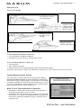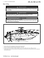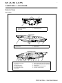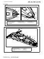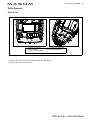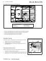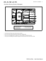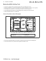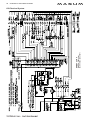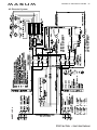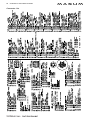
1
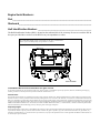
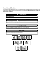
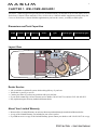
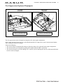
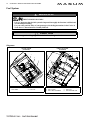
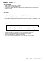
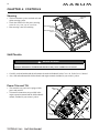
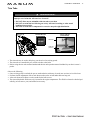
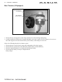
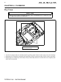
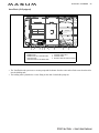
Engine Serial Numbers:
Port______________________________________________________________
Starboard_________________________________________________________
Hull Identification Number: __________________________________________
The Hull Identification Number (HIN) is located on the starboard side of the swimstep. Be sure to record the HIN in
the space provided above and refer to the HIN for any correspondence or orders.
Record the HIN and the engine serial number in the space provided above.
Please refer to the HIN for any correspondence or orders.
HIN LOCATION
© 2002 Maxum Marine Technical Publications. All rights reserved.
No part of this publication may be reproduced, stored in any retrieval system, or transmitted in any form by any means, electronic, mechanical, photocopying,
recording or otherwise, without prior written permission of Maxum. Printed in the U.S.A.
General Notes
The material in this document is for information only and is subject to change without notice. While reasonable efforts have been made in the preparation of this
document to assure its accuracy, Maxum assumes no liability resulting from errors or omissions in this document, or from the use of information contained herein.
Due to our commitment to product improvement, Maxum reserves the right to make changes in the product design, specifications and equipment at any time without notice or obligation. Illustrations and/or photos may show optional equipment. All Maxum products meet or exceed USCG (Unites States Coast Guard) and/or
NMMA (National Marine Manufacturer’s Association) construction standards. Manufactured with 1,1,1 Trichloroethane, a substance which harms public health
and environment during the manufacturing process by destroying ozone in the upper atmosphere.
Proprietary Rights
This document discloses subject matter in which Maxum has proprietary rights. The information and design disclosed herein were originated by and are the property of Maxum. Neither receipt nor possession thereof confers or transfers any right to reproduce, copy, alter or disclose the document or any part thereof, any
information contained therein, or to construct boats or any item from it, except by written permission from or written agreement with Maxum. This document is to
be returned upon request to Maxum.
CONTENTS
CHAPTER 1: WELCOME ABOARD!
CHAPTER 4: CONTROLS
1
1
1
1
2
2
2
3
3
3
3
4
16
16
16
17
18
Dimensions and Tank Capacities
Layout View
Dealer Service
About Your Limited Warranty
Boating Experience
Safety Standards
Engine & Accessories Guidelines
Qualified Maintenance
Structural Limitations
Special Care For Moored Boats
Sacrificial Anodes (Zincs)
Carbon Monoxide (CO)
5 Sources of CO
5 Carbon Monoxide Alarm System
5 What To Do If Carbon Monoxide
Is Detected
6
Boat Lifting
CHAPTER 2: LOCATIONS
7
8
CHAPTER 5: NAVIGATION &
COMMUNICATIONS EQUIPMENT
19
19
19
19
20
22
23
Engines
Engine Room Ventilation System
Fire Suppression System (If Equipped)
Fuel System
14
15
15
15
Diagrams
Fuel Fill and Vent
Fuel Filters
Anti-siphon Valve
Freshwater System
24 Transom Shower
24 Water Heater
24 City Water Inlet
25
Drain Systems
25
26
26
26
27
CHAPTER 3: PROPULSION &
RELATED SYSTEMS
12
12
13
14
Seawater Systems
22 Seacocks
22 Seawater Strainers
Deck Views
Component Locations
Bilge Pumps
21 Autofloat Switches
10 Helm
11
VHF Radio
Compass
Depth Finder
Global Positioning System (GPS)
(If Equipped)
CHAPTER 6: PLUMBING
Exterior Views
7 Hull views
Steering
Shift/Throttle
Power Trim and Tilt
Trim Tabs
Bow Thruster (If Equipped)
28
Deck Drains
Gray Water Drain System (If Equipped)
Sump Box Cleaning
Sump System Winterization
Gray Water Recovery System
(If Equipped)
Marine Head With Holding Tank
28 Electric Flush Marine Head (If Equipped)
29 VacuFlush (If Equipped)
30 Macerator (If Equipped)
CHAPTER 7: DECK EQUIPMENT
CHAPTER 12: ELECTRICAL SYSTEM
31
32
32
32
40
Canvas
Windlass (If Equipped)
Windshield Wiper
Cleats and Tow Eyes
CHAPTER 8: APPLIANCES &
ENTERTAINMENT SYSTEMS
33
33
34
35
35
Refrigerator
Electric Stove (If Equipped)
Alcohol/Electric Stove (If Equipped)
Audio & Visual Equipment
Dockside Cable TV & Telephone
(If Equipped)
40
41
41
41
41
42
43
48
38
38
38
38
Care and Maintenance
Navigation Lights
Interior & Exterior Lights
Spotlight (If Equipped)
CHAPTER 11: HEATING &
AIR CONDITIONING
39
Air Conditioning System (If Equipped)
120 Volt AC System
Generator (If Equipped)
49 Gas Generator
51 Diesel Generator
53
Electrical Routings
53
53
54
54
Deck Electrical Harness
Hull Electrical Harness
Battery System
Bow Thruster Battery System
(If Equipped)
55 120 Volt AC System
56 Bonding Harness
Dinette/Berth
Aft Cockpit Table/Sunlounge
CHAPTER 10: LIGHTS
Batteries
Alternator
Battery Charger
12 Volt Accessory Outlets
Fuses and Circuit Breakers
Battery Switches
44 Shore Power
46 Connecting To Shore Power
47 Transfer Switch (If Equipped with
Dual Shore Power)
CHAPTER 9: CONVERTIBLE SEATS,
BEDS, & TABLES
36
37
12 Volt DC System
57
Wire Diagrams
57
58
59
60
Engine Electrical System
DC Electrical System
AC Electrical System
Connector List
Hazard Boxes & Symbols
The hazard boxes and symbols shown below are used throughout this supplement to call attention to potentially dangerous situations which could lead to either personal injury or product damage. Read ALL warnings carefully and
follow all safety instructions.
DANGER!
!
This box alerts you to immediate hazards which WILL cause severe personal injury or death if
the warning is ignored.
!
WARNING!
This box alerts you to hazards or unsafe practices which COULD result in severe personal
injury or death if the warning is ignored.
!
CAUTI ON!
This box alerts you to hazards or unsafe practices which COULD result in minor personal
injury or cause product or property damage if the warning is ignored.
NOTICE
This box calls attention to installation, operation or maintenance information, which is important to proper operation but is not hazard related.
FIRE
HAZARD!
EXPLOSION
HAZARD!
CO POISONING
HAZARD!
ELECTRICAL
HAZARD!
FALLING
HAZARD!
NO OPEN
FLAME!
HOT
HAZARD!
ROTATING
PROPELLER HAZARD!
RUN BILGE BLOWERS
FOR 4 MINUTES!
1
CHAPTER 1: WELCOME ABOARD!
This Owner’s Manual Supplement provides specific information about your boat that is not covered in the Cruiser &
Yacht Owner’s Manual. Please study the Cruiser & Yacht Owner’s Manual and this supplement carefully. Keep the
Cruiser & Yacht Owner’s Manual and this supplement on your boat in a secure, yet readily available place.
Dimensions and Tank Capacities
Overall
Bridge
Draft
Draft (Drive
Length Clearance Beam (Drive Up)
Down)
30' 9"
12' 9"
9' 10"
2' 1"
3' 5"
Fuel Capacity
(gal.)
150
Freshwater
Waste Holding
Capacity (gal.) Tank Capacity (gal.)
35
30
Layout View
Dealer Service
•
•
•
•
•
Ask your dealer to explain all systems before taking delivery of your boat.
Your dealer is your key to service.
Contact your dealer if you have any problems with your new boat.
If your dealer cannot help, call our customer service hotline: 360-435-8957 or send us a FAX: 360-403-4235.
Buy replacement parts from any authorized Maxum dealer.
About Your Limited Warranty
• Maxum offers a Limited Warranty on each new Maxum purchased through an authorized Maxum dealer.
• A copy of the Limited Warranty was included in your owner’s packet.
• If you did not receive a copy of the Limited Warranty, please contact your dealer or call 360-435-8957 for a copy.
2
CHAPTER 1: WELCOME ABOARD!
Boating Experience
!
WARNING!
CONTROL HAZARD! A qualified operator must be in control of the boat at all times. DO NOT
operate your boat while under the influence of alcohol or drugs.
If this is your first boat or if you are changing to a type of boat you are not familiar with, for your own comfort and
safety, obtain handling and operating experience before assuming command of the boat.
Take one of the boating safety classes offered by the U.S. Power Squadrons or the U.S. Coast Guard Auxiliary. For
more course information, including dates and locations of upcoming classes, contact the organizations directly:
• U.S. Power Squadrons: 1-888-FOR-USPS (1-888-367-8777) or on the Internet at: http://www.usps.org
• U.S. Coast Guard Auxiliary: 1-800-368-5647 or on the Internet at: http://www.cgaux.org
Outside the United States, your selling dealer, national sailing federation or local boat club can advise you of local
sea schools or competent instructors.
Safety Standards
DANGER!
DANGER
!
PERSONAL SAFETY HAZARD! DO NOT allow anyone to ride on parts of the
boat not designated for such use. Sitting on seat backs, lounging on the forward
deck, bow riding, gunwale riding or occupying the transom platform while
underway is especially hazardous and will cause personal injury or death.
DANGER!
DANGER
!
PERSONAL SAFETY HAZARD! ALWAYS secure the anchor and other loose objects before getting underway. The anchor and other items that are not properly secured can come loose when
the boat is moving and cause personal injury or death.
Your boat’s mechanical and electrical systems were designed to meet safety standards in effect at the time it was
built. Some of these standards were mandated by law, all of them were designed to insure your safety, and the safety
of other people, vessels and property.
In addition to this owner’s manual supplement, please read the Cruiser & Yacht Owner’s Manual and all accessory instructions for important safety standards and hazard information.
Engine & Accessories Guidelines
NOTICE
When storing your boat please refer to your engine’s operation and maintenance manuals.
Your boat’s engines and accessories were selected to provide optimum performance and service. Installing different
engines or other accessories may cause unwanted handling characteristics. Should you choose to install different
engines or to add accessories that will affect the boat’s running trim, have an experienced marine technician perform
a safety inspection and handling test before operating your boat again.
Certain modifications to your boat can result in cancellation of your warranty protection. Always check with
your dealer before making any modifications to your boat.
The engines and accessories installed on your boat come with their own operation and maintenance manuals. Read
and understand these manuals before using the engines and accessories.
CHAPTER 1: WELCOME ABOARD!
3
Qualified Maintenance
!
WARNING!
To maintain the integrity and safety of your boat, allow only qualified personnel to perform
maintenance on, or in any way modify: The steering system, propulsion system, engine control
system, fuel system, environmental control system, electrical system or navigational system.
Failure to maintain your boat’s systems (listed in the warning above) as designed could violate the laws in your jurisdiction and could expose you and other people to the danger of bodily injury or accidental death. Follow the instructions provided in the Cruiser & Yacht Owner’s Manual, this Owner’s Manual Supplement, the engine owner’s manual
and all accessory instruction sheets and manuals included in your boat’s owner’s packet.
Structural Limitations
The transom platform and bow platform are designed to be lightweight for proper boat balance. The load limit for
these platforms is 30 pounds per square foot, evenly distributed.
Special Care For Moored Boats
NOTICE
• To help seal the hull bottom and reduce the possibility of gelcoat blistering on moored boats,
apply an epoxy barrier coating, such as INTERLUX, Interprotect 2000E/2001E. The barrier
coating should be covered with several coats of anti-fouling paint.
• Many states regulate the chemical content of bottom paints in order to meet environmental
standards. Check with your local dealer about recommended bottom paints, and about the
laws in effect in your area.
Whether moored in saltwater or freshwater, your boat will collect marine growth on its hull bottom. This will detract
from the boat’s beauty, greatly affect its performance and may damage the gelcoat. There are two methods of slowing
marine growth:
• Periodically haul the boat out of the water and scrub the hull bottom with a bristle brush and a solution of soap
and water.
• The hull below the waterline may have anti-fouling paint applied by the factory. Occasionally you will need to repaint it with a good grade of anti-fouling paint.
Sacrificial Anodes (Zincs)
NOTICE
Do not paint between the zinc and the metal surface it contacts and do not paint over the zincs.
Your boat is equipped with sacrificial anodes (zincs) to protect underwater metal parts from excessive deterioration.
Check the zincs regularly and replace them if they have deteriorated more than 70%.
There are many factors that affect the rate at which the zincs deteriorate, including:
• Water temperature
• Salinity
• Water pollution
Stray electrical current from the boat or dock may cause complete deterioration in just a few weeks. If there is rapid
zinc deterioration, measure the electrolytic corrosion around your boat with a Corrosion Test Meter. If the zincs are
not bonded correctly, they will not provide protection.
4
CHAPTER 1: WELCOME ABOARD!
Carbon Monoxide (CO)
!
DANGER!
CARBON MONOXIDE POISONING HAZARD!
DANGER
Carbon monoxide gas (CO) is colorless, odorless, and extremely dangerous. All
engines, generators, and fuel burning appliances produce CO as exhaust. Direct and
prolonged exposure to CO will cause BRAIN DAMAGE or DEATH.
Signs of CO poisoning include:
• Headache
• Nausea
• Dizziness
• Drowsiness
•
•
•
•
CO poisoning causes a significant number of boating deaths each year.
Called the "silent killer", CO is an extremely toxic, colorless, odorless and tasteless gas.
Breathing CO blocks the ability of your blood to carry oxygen.
The effects are cumulative, even low levels of exposure can result in injury or death.
Factors increasing the effects of CO poisoning include:
• Age
• Smokers or people exposed to high concentrations of cigarette smoke
• Consumption of alcohol
• Lung disorders
• Heart problems
• Pregnancy
CHAPTER 1: WELCOME ABOARD!
Sources of CO
Sources of CO include:
a. Using engines or generator when boat is moored
in a confined space.
b. Mooring close to
another boat that
is using its engine,
generator or any
other CO source.
c. Running boat with
trim angle of bow
too high.
d. Running boat without
through ventilation
(station wagon effect).
To correct stationary situations (a) and/or (b):
• Close all windows, portlights and hatches.
• If possible, move your boat away from the source of CO.
To correct running situations (c) and/or (d):
• Trim bow down.
• Open windows and canvas.
• When possible, run boat so that prevailing winds will help dissipate exhaust.
Immediately take corrective action if CO is detected or suspected (see, Carbon Monoxide Alarm System, below).
Carbon Monoxide Alarm System
Your boat features a carbon monoxide (CO) alarm system. Do not
disconnect the alarm system. Read and understand the manufacturer’s
instructions for your CO alarm system. If you did not receive an instruction manual, call (800) 383-0269 and one will be mailed to you. If your
boat is not equipped with a carbon monoxide alarm, consider purchasing one from your dealer or marine supply store.
What To Do If Carbon Monoxide Is Detected
• Immediately ventilate and evacuate any enclosed spaces that are
occupied by people and reset your CO alarm.
• Immediately move anyone showing any symptoms of CO poisoning
into fresh air. See a doctor if any symptoms persist. If the person is
unconscious, immediately administer oxygen or CPR and call for
emergency help.
MARINE TECHNOLOGIES INC.
CARBON MONOXIDE ALARM - MODEL 60-541
(REPLACE AFTER TEN YEARS OF USE)
5
6
CHAPTER 1: WELCOME ABOARD!
Boat Lifting
!
WARNING!
PERSONAL INJURY and /or PRODUCT or PROPERTY DAMAGE HAZARD!
• Lift slings may slip on the hull. Avoid serious injury or death by securing the slings together
before lifting.
!
WARNING!
PERSONAL INJURY and /or PRODUCT OR PROPERTY DAMAGE HAZARD!
• NEVER Lift the boat using the bow and stern eyes or the cleats.
!
CAUTI ON!
PRODUCT or PROPERTY DAMAGE HAZARD!
• When lifting any boat, always use a spreader bar. The spreader bar must be equal to the
width of the boat at the lifting point.
16"
14"
LIFTING SLING LABELS (TYPICAL PORT & STARBOARD)
•
•
•
•
Always follow the lift equipment’s instructions and requirements.
Water in the bilge can shift and change the balance of the load.
If water is present in the bilge, pump or drain the water out of the bilge areas before lifting your boat.
When lifting your boat, always position the lifting slings at the port and starboard sling label positions as shown in
the illustration above.
7
CHAPTER 2: LOCATIONS
Exterior Views
Hull views
TRANSOM
1
3
1
2
3
4
2
5
STERN EYES (STRONG POINTS)
BOARDING LADDER
TRIM TABS
3
4
5
ZINC PLATE
BILGE DRAIN PLUG
PORT HULLSIDE
1
1
2
2
3
BOW EYE (STRONG POINT)
PORTLIGHTS
3
4
4
GENERATOR EXHAUST (IF EQUIPPED)
DECK DRAIN
STARBOARD HULLSIDE
1
1
2
3
4
5
6
7
2
3
4
5
DECK DRAINS
AFT BILGE PUMP DRAIN
FUEL VENT
WATER TANK VENT
HOLDING TANK VENT
WATER HEATER DRAIN
SINK DRAIN
6 7
8
9
10
8
9
10
11
12
13
11
12
13
GRAY WATER TANK DRAIN (IF EQUIPPED)
GRAY WATER TANK VENT (IF EQUIPPED)
AIR CONDITIONER DRAIN (IF EQUIPPED)
PORTLIGHTS
FORWARD BILGE PUMP DRAIN
ANCHOR LOCKER DRAIN
8
CHAPTER 2: LOCATIONS
Deck Views
FOREDECK
7
3
5
9
1
4
2
1
9
6
8
1
1
2
3
CLEATS (STRONG POINTS)
WINDLASS (IF EQUIPPED)
WINDLASS CONTROLS
(IF EQUIPPED)
4
5
6
ANCHOR ROLLER
ANCHOR DEAD END
SPOTLIGHT (IF EQUIPPED)
7
8
9
ANCHOR LOCKER DRAIN
HIDDEN HORN
NAVIGATION LIGHTS
MID-DECK
1
2
3
4
5
6
7
8
1
2
3
4
ALL AROUND LIGHT
RADAR (IF EQUIPPED)
TV ANTENNA (IF EQUIPPED)
WIPER
5
6
7
8
VENTILATION HATCHES
GRAB RAILS
BOW RAIL
BOW HATCH
CHAPTER 2: LOCATIONS
1
4
AFT DECK
6
7
2
2
1
3
2
1
1
2
3
4
GRAB RAIL
CLEAT (STRONG POINT)
WATER FILL DECK FITTING
COURTESY LIGHT
5
6
7
8
8
5
TRANSOM SHOWER
FUEL FILL DECK FITTING
WASTE PUMP-OUT DECK FITTING
TRANSOM STORAGE BOX
9
10
CHAPTER 2: LOCATIONS
Helm
NOTE: TYPICAL HELM LAYOUT SHOWN
ACTUAL LAYOUT MAY VARY DEPENDING
ON ENGINE AND ACCESSORY OPTIONS
4
5
6
7
8
9
5
4
1
3
2
10
11
12
13
14
3
2
21
22
23
24
24
25
26
15
1
27
16
29
23
23
24
24
30
31
32
28
20
19
18
17
17
1
2
3
4
5
6
7
8
9
10
VOLTMETER
TEMP GAUGE
OIL GAUGE
POWER TRIM & TILT GAUGE
TACHOMETER
COMPASS
FUEL GAUGE
SPEEDOMETER
DEPTH SOUNDER
SPOTLIGHT CONTROL
(IF EQUIPPED)
11 WINDLASS CONTROL
(IF EQUIPPED)
12 BOW THRUSTER CONTROL
(IF EQUIPPED)
13 12 VOLT ADAPTER
14 THROTTLE/SHIFT LEVER
15 TRIM TAB SWITCH
16 VHF RADIO
17 COURTESY LIGHTS
18 CIRCUIT BREAKER PANEL
19 ENGINE IGNITION
20 EMERGENCY ENGINE
SHUT DOWN
21 INSTRUMENT LIGHT
22 NAVIGATION LIGHT
23
24
25
26
27
28
29
30
31
32
COURTESY LIGHT SWITCHES
ACCESSORIES SWITCHES
FORWARD BILGE PUMP
DEPTH SOUNDER
BLOWER
STEREO CONTROL
(IF EQUIPPED)
ANCHOR LIGHT
AFT BILGE PUMP
WIPER SWITCH
HORN
CHAPTER 2: LOCATIONS
11
Component Locations
12 Volt Accessory Outlets: (1) At the helm on the dash panel. (2) in the TV cabinet.
Air Conditioner Seawater Intake Seacock: In the engine compartment on the starboard side.
Air Conditioner Unit: In the V-berth. The cutouts under the V-berth mattress provide access to the air conditioner unit.
Batteries: On the port side of the engine compartment.
Battery Charger: On the port side of the engine compartment on the front wall.
Battery Switches: On the starboard side of the transom storage box.
Bilge pump - Aft: In the engine compartment.
Bilge pump - Forward: Under the salon floor. Access is through the floor cutout under the entry steps.
Bow Thruster Motor: In the V-berth. The cutouts under the V-berth mattress provide access to the motor.
Bow Thruster Battery Switch: Under the galley sink.
Bow Thruster Gear Oil Reservoir: Under the galley sink.
Carbon Monoxide Detector: In the salon above the dinette.
DC Circuit Breakers: At the helm under the dash panel on the right.
Depth Sounder Transducer: In the engine compartment.
Engine Circuit Breakers: On the engine.
Fuel Fill: On the starboard aft corner of the deck.
Fuel Tank: In the engine compartment at the front.
Generator Control Panel: On or near the AC panel in the galley.
Generator Seawater Intake Seacock: In the engine compartment on the port side.
Generator Circuit Breaker: On the generator.
Macerator Underwater Discharge Seacock: In the engine compartment on the port side.
Marine Head (Electric) Seawater Intake Seacock: Under the salon floor. The floor cutout under the entry steps
provides access to the seacock.
Navigation lights: Red and green lights at the bow. White all-around light on the radar wing.
Transom Shower: At the cockpit entry gate.
Waste Holding Tank: In the engine compartment on the starboard side.
Water Fill: On the port aft corner of the deck.
Water Heater: In the machinery compartment. The starboard wall cutouts in the mid-berth provide access to the
water heater.
Water Pump: In the machinery compartment. The starboard wall cutouts in the mid-berth provide access to the
water pump.
Water Pump Switch: In the galley above the sink.
Water Tank: In the engine compartment on the starboard side.
Windlass Circuit Breakers: On the port side of the transom storage box.
Windlass Circuit Foot Controls: At the bow in the rope locker.
12
CHAPTER 3: PROPULSION & RELATED SYSTEMS
Engines
The owner’s packet contains detailed engine operation and maintenance manuals. Be sure to read and understand
these manuals before starting or doing any maintenance on the engines.
Engine Room Ventilation System
WARNING!
!
•
•
•
•
FIRE/EXPLOSION HAZARD
Use of the blower system is NOT A GUARANTEE that explosive fumes have been removed.
If you smell fuel, DO NOT start the engine or generator and DO NOT turn on any
electrical devices.
If you smell fuel and the engines and/or generator is already running, SHUT OFF the
engines and/or generator and TURN OFF all electrical devices. Investigate immediately.
DO NOT obstruct or modify the ventilation system.
1
2
1
2
•
•
•
•
VENTILATION HOSES
BLOWER MOTORS
The bilge blower removes explosive fuel fumes from the engine compartment.
Fresh air is drawn into the compartment through the deck vents.
The bilge blower switch is at the helm.
If your boat is equipped with a generator, there is a second bilge blower switch on the main AC panel.
To make sure the engine compartment is ventilated with fresh air, run the bilge blower:
• For at least four minutes before starting the engines.
• During starting.
• Anytime your boat is running below cruising speed.
CHAPTER 3: PROPULSION & RELATED SYSTEMS
13
Fire Suppression System (If Equipped)
GAS SYSTEM
(IF EQUIPPED)
DIESEL SYSTEM
(IF EQUIPPED)
2
1
1
2
1
2
FIXED FIRE EXTINGUISHER
MANUAL DISCHARGE HANDLE
1
2
FIXED FIRE EXTINGUISHER
TO MANUAL DISCHARGE HANDLE
The fire suppression system is designed to extinguish a fire in the engine compartment.
Before using your boat for the first time, read and understand the fire suppression system’s instruction and maintenance manual and follow all warnings.
Observe the following:
• The system will go off automatically whenever direct heat from a fire is detected in the engine compartment.
• The system can be set off manually by pulling the T-handle (labeled "FIRE") at the helm.
• The system can only be set off once during a fire. After the system is discharged it must be refilled and refurbished
before it can be used again.
14
CHAPTER 3: PROPULSION & RELATED SYSTEMS
Fuel System
WARNING!
!
FIRE/EXPLOSION HAZARD!
• It is very important that the fuel system be inspected thoroughly the first time it is filled and
at each subsequent filling.
• For your safety and the safety of your passengers, the fueling instructions in the Cruiser &
Yacht Owner’s Manual must be carefully followed.
CAUTION
!
Avoid the storage or handling of gear near the fuel lines, fittings and tank.
Diagrams
GAS FUEL SYSTEM
(IF EQUIPPED)
DIESEL FUEL SYSTEM
(IF EQUIPPED)
3
4
5
1
2
1
2
1
6
4
3
3
1
2
FUEL LINE TO ENGINE
FUEL TANK
3
4
FUEL TANK VENT
FUEL FILL
1
2
3
FUEL TANKS
FUEL FILTER
FUEL LINE TO ENGINE
4
5
6
FUEL TANK VENT
FUEL FILL
FUEL RETURN LINE
CHAPTER 3: PROPULSION & RELATED SYSTEMS
Fuel Fill and Vent
• The fuel fill fitting is marked “GAS” or “DIESEL”.
• The fuel tank vent is located below the fuel fill.
• If you experience difficulty filling the fuel tank, check to see that the fuel fill hose and vent hose are free of
obstructions and kinks.
Fuel Filters
•
•
•
•
The fuel pickup tube (located inside the fuel tank) is equipped with a fine mesh screen filter.
In addition, when supplied by the engine manufacturer, a fuel filter is installed on the engines.
Periodically replace the fuel filters to make sure they remain clean and free of debris.
Consult with your selling dealer or local marina concerning fuel additives that help to prevent fungus or other
buildup in your fuel tank.
Anti-siphon Valve
NOTICE
• If an engine running problem is diagnosed as fuel starvation, check the anti-siphon valve. If
the valve is stuck or clogged, change or replace it while the engines are shut down.
• NEVER run the engines with the anti-siphon valve removed, except in an emergency.
•
•
•
•
Your boat is equipped with an anti-siphon valve, which is an integral part of fuel system.
The valve is located at the point where the fuel feed line attaches to the fuel tank.
The valve is spring loaded and is opened by fuel pump vacuum.
This valve will prevent fuel from siphoning from the tank in the event of a fuel line rupture.
15
16
CHAPTER 4: CONTROLS
Steering
STEERING
CABLE
• This boat features a power assisted rack-andpinion steering system.
• Check the fluid level in the power steering
reservoir every time you use your boat.
• Boat steering is not self-centering.
SHIFT/THROTTLE
LEVER
SHIFT/THROTTLE
CABLE
Shift/Throttle
!
WARNING!
LOSS OF CONTROL HAZARD!
Improper maintenance of shift/throttle hardware may cause a sudden loss of control!
• Carefully read and understand the information about the shift/throttle in the Cruiser & Yacht Owner’s Manual.
• Also, read and understand the shifter/throttle and engine manuals included in your owner’s packet.
Power Trim and Tilt
• The sterndrive on your boat is equipped with
power trim and tilt.
• Trim and tilt instructions are provided in the
engine operation manual and the shifter/throttle
manual, included in your owner’s packet.
TRIM/TILT
PUMPS
TRIM TAB
PUMP
CHAPTER 4: CONTROLS
17
Trim Tabs
!
WARNING!
LOSS OF CONTROL HAZARD!
Improper use of trim tabs will cause loss of control!
• DO NOT allow anyone unfamiliar with trim tabs to use them.
• DO NOT use trim tabs in a following sea as they will cause broaching or other unsafe
handling characteristics.
• DO NOT use trim tabs to compensate for excessive unequal weight distribution.
VIEW OF HELM
TYPICAL TRIM TAB
ROCKER SWITCHES
TYPICAL TRIM TAB
(TRANSOM VIEW)
TRANSOM
TRIM TAB
(TYPICAL)
• The trim tabs may be used to help keep your boat level at cruising speeds.
• The trim tabs are controlled by two rocker switches at the helm.
• Before using the trim tabs read and understand the trim tab operation manual included in your boat’s owner’s
packet.
Observe the following:
• Once cruising speed is reached, the port or starboard trim switch may be used (one at a time) to level the boat.
• Perform trim tab adjustment with several short touches to the switch rather than one long one.
• After each short touch allow several seconds for the hull to react.
• The trim tab hydraulic fluid reservoir is located in the engine compartment. The fluid level must be checked periodically (at least once a year) and refilled as necessary.
18
CHAPTER 4: CONTROLS
Bow Thruster (If Equipped)
BOW THRUSTER GEAR
OIL RESERVOIR
BOW THRUSTER
BATTERY SWITCH
• The bow thruster (if equipped) is used to help control the boat when docking and departing.
• Carefully read the bow thruster user’s manual included in your owner’s packet. See the Component Location section of this Supplement for the location of the system’s battery switch and gear oil reservoir.
Observe the following about the bow thruster system:
• The bow thruster is an all electric system and is independent of the boat’s engines.
• The bow thruster system has its own dedicated 2 position battery switch and battery.
• The boat’s engine alternators do not charge the bow thruster battery.
• The bow thruster battery can only be charged with the
battery charger.
19
CHAPTER 5: NAVIGATION & COMMUNICATIONS EQUIPMENT
The owner’s packet contains manuals for all navigation & communication equipment installed on your boat. Thoroughly read and understand these manuals before using these systems for the first time and observe the following:
VHF Radio
Your boat may include a VHF (Very High Frequency) radio. The VHF radio can be used to access weather reports,
summon assistance or contact other vessels as permitted by the FCC (Federal Communications Commission). Contact the FCC for licensing, rules and regulations concerning VHF radio usage.
Compass
NOTICE
• Compass accuracy can be affected by many factors.
• Have a qualified technician calibrate your compass.
• Make sure the technician gives you a deviation card which shows the corrections to apply in
navigational calculations.
• Keep a copy of the deviation card at each helm.
Depth Finder
!
WARNING!
• DO NOT use the depth finder as a navigational aid to prevent collision, grounding, boat
damage or personal injury.
• When the boat is moving, submerged objects will not be seen until they are already under
the boat.
• Bottom depths may change too quickly to allow time for the boat to react.
• If you suspect shallow water or submerged objects, run the boat at very slow speeds.
Global Positioning System (GPS) (If Equipped)
!
WARNING!
• The GPS system should not be relied upon as the only aid to navigation.
• A qualified operator must monitor the GPS system at all times and keep look-out for other
marine traffic and possible collision situations.
NOTICE
Τhe GPS system is only an aid to navigation. It's accuracy can be affected by many factors,
including equipment failure or defects, environmental conditions & improper handling or use.
20
CHAPTER 6: PLUMBING
Bilge Pumps
NOTICE
Discharge of oil, oil waste or fuel into navigable waters is prohibited by law. Violators are subject to legal action by the local authorities.
2
1
1
2
BILGE PUMPS & FLOAT SWITCHES
BILGE PUMP DRAINS
• Your boat is equipped with two automatic impeller-type bilge pumps which are used to pump water out of the bilge.
• Bilge pumps are controlled by automatic bilge pump float switches (autofloat switches) and/or switches at the helm.
• Bilge pumps are wired directly to the battery so they will normally function even when the boat is completely shut
down and left unattended.
CHAPTER 6: PLUMBING
Bilge Pump Testing
• Bilge pumps are critical to the safety of your boat.
• Check the bilge pumps often to make sure that they
are working properly. Test each pump individually.
To test each bilge pump:
1.
2.
Turn on the manual switches at the helm.
Make sure that water in the bilge is
pumped overboard.
If there is water in the bilge and the pump motor is
running but not pumping:
1.
2.
Inspect the discharge hose for a kink or
collapsed area.
Check the bilge pump housing for clogging
debris as follows:
To check for clogging debris in pumps:
1.
2.
3.
TAB
SLOT (TYPICAL
EACH SIDE)
With your thumb and forefinger squeeze the
holding tabs on each side of the power cartridge.
Lift out the power cartridge.
Check the pump and the housing and clear
any debris.
Reinstall the power cartridge:
1.
2.
TABS
Align the tabs and slots and press firmly until the
tabs click into place.
Make sure that the power cartridge is locked
into place.
Autofloat Switches
• Automatic bilge pumps use electromagnetic float (autofloat) switches to turn on the pump whenever water
rises above a preset level in the bilge.
• One autofloat switch is mounted next to each automatic
bilge pump.
• Autofloat switches are wired directly to the battery and
will normally function even when the boat is completely shut down and left unattended.
KNOBS
To test a float switch:
1.
2.
3.
4.
Turn either white plastic knob 1/4 turn to lift the float
and turn on the bilge pump.
If the pump does not turn on, check the inline fuse.
If the fuse is good but the switch doesn’t work, it may
indicate a bad switch or possibly a low battery.
Release the knob to lower the float and return the float
switch to auto mode.
AUTOFLOAT
SWITCH
21
22
CHAPTER 6: PLUMBING
Seawater Systems
Seacocks
!
CAUTION!
SYSTEM DAMAGE HAZARD!
• Before using a seawater intake system, make sure that the system’s seacock is in the OPEN
position before the system is started and keep the seacock open until the system is shut off.
• Close the seacocks whenever the systems will not be used for long periods of time.
A seacock is a valve, controlled by a 90º lever, used to manage
the intake of seawater through the hull and below the water
line. Seacocks are typically used on your boat in the following
seawater intake systems:
• Generator (if equipped)
• Marine head (toilet)
• Air conditioning system (if equipped)
Before using any of these systems, make sure that the system’s
seacock is open and remains open until the system is shut off.
SEAWATER INTAKE VALVE (SEACOCK)
COMPONENTS (TYPICAL)
90 DEGREE
SEACOCK
LEVER
HULL
SECTION
SEACOCK (TYPICAL)
SEACOCK GASKET
INTAKE STRAINER
Seawater Strainers
• Seawater strainers are used in water pickup systems to filter incoming seawater.
• A seawater strainer is located near each system’s seacock.
• Check the strainers for leaks and/or debris every time you use your boat.
• If debris is found, clean the seawater strainer as follows:
!
CAUTION!
FLOODING HAZARD!
• The seacock that sends seawater to the strainer must be CLOSED before disassembling
the seawater strainer to prevent the boat from taking on water through the seawater
strainer assembly.
• Keep the seacock CLOSED until the seawater strainer is completely reassembled.
SYSTEM DAMAGE HAZARD!
• After reassembling the seawater strainer, make sure that the seacock valve is OPEN before
using the component/system.
1.
2.
3.
4.
5.
6.
7.
Make sure the component/system (generator, air conditioning system, etc.) that the strainer is connected to is
turned off.
Close the seacock that sends seawater to the strainer you are about to clean. The seacock must remain closed
until the strainer is completely reassembled.
Take apart the seawater strainer.
Remove the debris.
Flush the strainer with water.
Reassemble the seawater strainer.
Open the seacock and check for leaks around the strainer. If no leaks are found, you may use the component
or system.
CHAPTER 6: PLUMBING
23
Freshwater System
!
WARNING!
• Only use safe drinking (potable) water in your boat’s freshwater system.
• Only use a sanitary drinking water hose to fill the water tank or connect to city water.
• Never use a common garden hose for drinking water.
1
4
2
5
6
1
2
3
4
5
FRESHWATER ROUTING
7
CITY WATER INLET
COCKPIT SINK FAUCET
GALLEY SINK FAUCET
WATER FILL DECK FITTING
TRANSOM SHOWER
8
9
6
7
8
9
10
3
10
WATER TANK
WATER TANK VENT
WATER HEATER
WATER PUMP
HEAD FAUCET & SHOWER
Read the Freshwater System section in the Cruiser & Yacht Owner’s Manual. Your boat is equipped with a pressure
type (demand) freshwater (potable) system. This system can be pressurized two different ways:
1. By connecting the city water inlet to an onshore water supply.
2. By turning on the water pump.
• See the Component Location section of this Supplement for the location of the water pump switch.
• Since the water pump requires DC power, the "HOUSE BATTERY SWITCH" must be in the "1", "2" or "BOTH"
position for the pump to work.
Observe the following about the freshwater system:
• Turn off the water pump when the boat is not in use or the water tank is empty.
• Inspect and clean the water filter often (located on the water pump).
• When your boat is to be left unattended for long periods of time, pump the water tank dry to prevent stored water
from becoming stagnant and distasteful.
• To winterize the freshwater system, pump the water tank dry and drain the system by opening the water filter.
• If the freshwater system needs to be disinfected, ask your dealer about treatments available for your boat’s system.
24
CHAPTER 6: PLUMBING
Transom Shower
Your boat is equipped with a freshwater transom shower. The water pump switch must be turned on before using the
transom shower. Be sure to read the manufacturer’s instructions, provided in your boat’s owner’s packet.
Water Heater
!
WARNING!
HOT HAZARD! Water heated by the water heater can reach temperatures hot enough
to scald the skin.
!
CAUTI ON!
WATER HEATER DAMAGE HAZARD!
• DO NOT turn on the water heater electrical circuit on the AC panel until the water heater
tank is COMPLETELY filled with water.
• Even momentary operation in a dry tank will damage the heating elements.
• Warranty replacements WILL NOT be made on elements damaged in this manner.
• The tank is full if water flows from the tap when the hot water is turned on in the galley.
• The water heater should be drained and the power turned OFF when the possibility of
freezing exists.
• The water heater is connected to the AC power system, therefore, you must make sure that the water heater
breaker on the AC panel is turned ON before water will be heated.
• Read the manufacturer’s instruction manual supplied in your boat’s owner’s packet and observe the
warnings above.
City Water Inlet
!
CAUTI ON!
FLOODING & SWAMPING HAZARD!
• NEVER leave the boat unattended while using the "city water" feature.
• Any leak or break in the system may allow large amounts of water to accumulate in the
bilge.
• This could cause swamping of the batteries and engines or sinking of the boat.
• Read the "City Water Hookup" portion of the Freshwater System section in the Cruiser & Yacht Owner’s Manual.
• When the boat is connected to a dockside water supply, the freshwater system is pressurized.
• You do not need to turn on the water pump’s DC breaker.
CHAPTER 6: PLUMBING
Drain Systems
Deck Drains
NOTE: VIEWS ARE UNDERSIDE OF DECK
1
4
2
2
5
3
3
1
1
2
3
STORAGE TUB DRAINS
COCKPIT DRAINS
THRU-HULL DRAIN FITTINGS
4
5
COOLER STORAGE DRAIN
ROPE LOCKER DRAIN
• Water on the deck is drained overboard through the deck drains.
• Keep the deck drains free of debris.
25
26
CHAPTER 6: PLUMBING
Gray Water Drain System (If Equipped)
8
7
6
5
4
1
2
1
2
3
4
•
•
•
•
3
COCKPIT SINK DRAIN
SYSTEM DRAIN THRU-HULL
MANIFOLD
HEAD SINK DRAIN
5
6
7
8
SHOWER DRAIN
FORWARD BILGE PUMP DRAIN
SUMP PUMP BOX
GALLEY SINK DRAIN
The gray water drains above the water line are gravity drained overboard
The gray water drains below the water line drain into a sump pump box.
A float switch automatically turns on the sump pump.
The sump pump pumps the shower water overboard.
Sump Box Cleaning
Periodically clean the sump pump box (A), filter, and pump as follows:
1.
2.
3.
SUMP PUMP BOX IS ACCESSED THROUGH
FLOOR CUT OUT UNDER SALON ENTRY STEPS
C
Remove the cover screws (B) and the cover (C).
Remove any debris from the box and the filter.
Clean the sump pump as outlined in the Bilge Pump section of
this Supplement.
Sump System Winterization
Drain the sump pump system in the winter months when not in use.
1.
2.
3.
Disconnect and drain all lines to the unit.
Remove the screws from the mounting feet (D) and drain the system.
Reinstall the screws in the mounting feet and reconnect the system.
A
D
B
CHAPTER 6: PLUMBING
Gray Water Recovery System (If Equipped)
1
2
3
4
7
1
2
3
4
•
•
•
•
6
GALLEY SINK DRAIN
GRAY WATER TANK
SHOWER DRAIN
HEAD SINK DRAIN
5
5
6
7
GREY WATER TANK VENT
GREY WATER PUMP-OUT
COCKPIT SINK DRAIN
Your boat may feature a gray water recovery system.
Gray water from the sinks and shower drain into a holding tank.
The gray water holding tank is connected to a deck fitting for dockside pump-out.
The gray water holding tank should be pumped out each time the fresh water tank is filled.
27
28
CHAPTER 6: PLUMBING
Marine Head With Holding Tank
•
•
•
•
•
Your boat is equipped with a marine head (toilet) and waste holding tank system.
Read the manufacturer’s operation and maintenance manual (included in your boat’s owner’s packet).
The holding tank is plumbed to a waste fitting on the deck for dockside pump-out.
You can determine the content level of the holding tank by looking at the side of the tank.
Empty the holding tank at every opportunity.
Electric Flush Marine Head (If Equipped)
6
1
2
3
5
4
SEAWATER PICKUP & BALL VALVE
MARINE HEAD
MARINE HEAD TO HOLDING TANK
3
4
5
6
2
1
HOLDING TANK VENT
HOLDING TANK
WASTE PUMP-OUT DECK FITTING
• The electric flush marine head uses seawater to flush waste from the toilet into the holding tank.
• The seawater intake valve (seacock) must be open for the head to work.
CHAPTER 6: PLUMBING
29
VacuFlush (If Equipped)
9
1
2
3
4
5
8
7
6
5
4
SEAWATER PICKUP & BALL VALVE
MARINE HEAD
MARINE HEAD TO VACUUM PUMP
VACUUM PUMP
VACUUM PUMP TO HOLDING TANK
3
6
7
8
9
2
1
HOLDING TANK VENT FILTER
HOLDING TANK VENT
HOLDING TANK
WASTE PUMP-OUT DECK FITTING
• The VacuFlush head system uses a vacuum pump and freshwater from the water tank to flush waste from the toilet
into the holding tank.
• The holding tank is plumbed to a waste fitting on the deck for dockside pump-out.
30
CHAPTER 6: PLUMBING
Macerator (If Equipped)
NOTICE
Check with local authorities for regulations regarding the legal use of marine head systems.
8
1
2
3
4
5
6
7
4
SEAWATER PICKUP & BALL VALVE
MARINE HEAD
MARINE HEAD TO HOLDING TANK
OVERBOARD DISCHARGE BALL VALVE
3
5
6
7
8
2
1
MACERATOR (IF EQUIPPED)
HOLDING TANK VENT
HOLDING TANK
WASTE PUMP-OUT DECK FITTING
To use the macerator to pump waste directly into the water (where regulations permit):
1.
2.
3.
Open the underwater discharge seacock.
Press both macerator switches at the same time to run the pump. Do not continue running the macerator if the
waste holding tank is empty.
Close the underwater discharge seacock when you are done pumping.
31
CHAPTER 7: DECK EQUIPMENT
Canvas
CAUTI ON!
!
Take down and securely stow the convertible top, side curtains and back cover before transporting your boat by road.
Forward canvas:
1.
2.
3.
Zip the forward canvas (A)
to the radar wing (B).
Slide the eye ends of the
forward main bow (C) into
the hinges on the windshield frame (D) and insert
the pins.
Unfold the forward canvas
and slide the eye ends of the
forward support legs (E) into
the hinges on the windshield frame (F) and insert
the pins.
L
H
G
B
A
L
E
I
C
F
L
H
D
I
J
J
Aft canvas:
1.
2.
3.
Zip the aft canvas (G) to the
radar wing (B).
Slide the eye ends of the aft
main bow (H) into the upper
deck hinges on the radar
wing (I) and insert the pins.
Unfold the aft canvas and
slide the eye ends of the aft
support legs (J) into the
lower hinges on the radar
wing (K) and insert the pins.
No adjustments to the bow jaw
slides (L) should need to be made
as they are preset during manufacturing. Before attempting to
adjust the jawslide positions,
obtain the correct measurements
from your selling dealer.
K
DETAIL VIEW OF TYPICAL
EYE END & HINGE
EYE END
PIN
HINGE
32
CHAPTER 7: DECK EQUIPMENT
Windlass (If Equipped)
!
CAUTI ON!
PRODUCT DAMAGE HAZARD!
• DO NOT pull the boat to the anchor using the windlass or continue to run the windlass if it
has stalled or is overloaded.
Your boat may feature an anchor windlass. Read and follow the manufacturer’s instruction manual supplied in your
boat’s owner’s packet before using the anchor windlass for the first time.
• The windlass can be controlled from a switch at the helm or from the deck foot switches.
• Make sure that the windlass breaker is turned on before using the anchor windlass.
• To haul the anchor, use engine power (not the windlass) to move the boat to, and directly above, the anchor.
• Use the windlass to dislodge the anchor from the bottom by pulling it straight up.
Windshield Wiper
When necessary, replace the wiper blade with an 18" blade refill.
Cleats and Tow Eyes
!
WARNING!
PERSONAL INJURY and /or PRODUCT or PROPERTY DAMAGE HAZARD!
• NEVER lift the boat using the bow and stern eyes or the cleats.
Carefully read the section on towing in the Cruiser & Yacht Owner’s Manual before towing anything behind the boat
or having the boat towed by another vessel.
33
CHAPTER 8: APPLIANCES & ENTER TAINMENT SYSTEMS
NOTICE
Always keep an approved ABC-type fire extinguisher in galley area.
All appliances installed on your boat come with their own manuals. These manuals contain detailed instructions and
important safeguards. Thoroughly read and understand these manuals before using your boat’s appliances.
• Make sure the AC breaker is turned on for the appliance you wish to use.
Refrigerator
Your boat features a 120-volt AC/12-volt DC refrigerator. The refrigerator runs on 12-volt DC power unless 120-volt
AC power is being supplied by the generator (if equipped) or shore power and the AC refrigerator breaker is on.
Electric Stove (If Equipped)
!
•
•
•
•
•
•
WARNING!
BURN/SCALDING and/or FIRE HAZARD!
Read the stove’s instruction manual before using.
Always keep an approved ABC-type fire extinguisher in galley area.
Do not use the stove while underway.
Any non-cooking devices on or near your stove during use are potential fire hazards!
DO NOT touch burners, grates or nearby surfaces as they may be hot even when they are
dark in color. Areas near burners and grates may become hot enough to cause burns.
During and after use, do not touch or let clothing or other flammable material come in contact with heated units or areas near the units (burner tops, main frame sides and back, sea
rails and pot holders) until they have had sufficient time to cool.
34
CHAPTER 8: APPLIANCES & ENTERTAINMENT SYSTEMS
Alcohol/Electric Stove (If Equipped)
!
DANGER!
CARBON MONOXIDE POISONING HAZARD!
• The alcohol stove is a source of dangerous carbon monoxide gas (CO).
• BEFORE using the alcohol stove, open doors and windows to make sure there is
enough fresh air for ventilation.
!
WARNING!
• Open flame cooking appliances consume oxygen, this can cause asphyxiation or death.
• Maintain open ventilation.
!
•
•
•
•
•
•
WARNING!
BURN/SCALDING and/or FIRE HAZARD!
Read the stove’s instruction manual before using.
Always keep an approved ABC-type fire extinguisher in galley area.
Do not use the stove while underway.
Any non-cooking devices on or near your stove during use are potential fire hazards!
DO NOT touch burners, grates or nearby surfaces as they may be hot even when they are
dark in color. Areas near burners and grates may become hot enough to cause burns.
During and after use, do not touch or let clothing or other flammable material come in contact with heated units or areas near the units (burner tops, main frame sides and back, sea
rails and pot holders) until they have had sufficient time to cool.
!
CAUTI ON!
PRODUCT DAMAGE HAZARD!
To prevent overheating which can destroy the electric burner elements, NEVER attempt to use
both alcohol and electric burners simultaneously.
CHAPTER 8: APPLIANCES & ENTERTAINMENT SYSTEMS
35
Audio & Visual Equipment
NOTICE
AM radio reception may be impaired anytime the engine or generator is running.
All audio and visual equipment installed on your boat have separate instruction sheets or manuals that explain their
use in detail.
Dockside Cable TV & Telephone (If Equipped)
• Your boat may be equipped with a dockside cable TV (television) and Telephone inlet..
• To receive cable TV transmissions, the boat must be hooked up to a dockside cable TV source.
• The boat must be hooked up to a dockside telephone line for a land based telephone to work.
36
CHAPTER 9: CONVER TIBLE SEATS, BEDS, & TABLES
Dinette/Berth
A
B
B
D
C
E
C
C
D
C
The dinette table can be removed and the dinette area can be converted into a berth.
1.
2.
3.
4.
5.
C
A
Remove the table (A) and the table leg (B).
Lift the dinette seat cushions (C).
Place the filler boards (D) securely into the recessed edge at the front of the dinette seats.
Put the dinette seat cushions (C) back down.
Place the filler cushion (E) on top of the filler boards (D).
C
D
CHAPTER 9: CONVERTIBLE SEATS, BEDS, & TABLES
37
Aft Cockpit Table/Sunlounge
D
A
B
C
The aft cockpit table and table leg can be removed and the seating can be converted into a flat sunlounge.
1.
2.
3.
4.
Remove the table (A) and table leg (B).
Put the filler board (C) in place so that it fits securely into the recessed edge at the front of the aft cockpit seats.
Place the filler cushion (D) on top of the filler board (C).
Make sure that all parts are secure before using the sunlounge.
38
CHAPTER 10: LIGHTS
Care and Maintenance
All of the lights installed on your boat are of top quality, but you should be aware that failure may periodically occur
for a variety of reasons:
1.
2.
3.
4.
There may be a blown fuse - replace the fuse.
The bulb may be burned out - carry spare bulbs for replacement.
A wire may be damaged or may have come loose - repair as required.
The bulb base may be corroded - clean the base and coat it with non-conductive electrical lubricant.
Navigation Lights
!
CAUTI ON!
Avoid the storage of gear where it would block navigation lights from view.
Read and understand the navigation light section of Cruiser & Yacht Owner’s Manual.
Interior & Exterior Lights
!
CAUTI ON!
• Be conservative in the use of battery power.
• Prolonged use of cabin interior lights (overnight) will result in a drained battery.
•
•
•
•
The lights are powered by the boat’s 12 volt DC system.
The "HOUSE BATTERY SWITCH" must be in the 1, 2 or BOTH position for the lights to work.
There are ON/OFF light switches for different sets of lights on the cabin wall.
Some individual lights also have a switch on the light.
Spotlight (If Equipped)
Your boat may come equipped with a spotlight which can be controlled by a switch at the helm. Instructions can be
found in the spotlight’s operating manual (included in your boat’s owner’s packet).
39
CHAPTER 11: HEATING & AIR CONDITIONIN G
Air Conditioning System (If Equipped)
!
DANGER!
CARBON MONOXIDE POISONING HAZARD!
Dangerous carbon monoxide gas (CO) can be brought into the boat through the air
conditioning system.
!
CAUTI ON!
SYSTEM DAMAGE HAZARD!
The air conditioning system’s seacock must be OPENED before turning on the air conditioner
and must remain OPEN during use.
1
4
5
6
1
2
3
4
5
7
GALLEY VENT
V-BERTH VENT
AIR CONDITIONER
SEAWATER PICKUP & BALL VALVE
SEA STRAINER
8
6
7
8
9
10
2
9
3
10
PICKUP PUMP
AFT BERTH VENT
HEAD VENT
DINETTE VENT
AIR CONDITIONER DRAIN
Your boat may be equipped with an air conditioning system. Read the air conditioner manual, included in your
owner’s packet, before using the air conditioning system.
• Before using the air conditioning system, make sure the breakers on the AC main distribution panel are turned on
and make sure the system’s seawater pickup seacock is open. The seacock must remain open anytime the air
conditioner is in use.
• The seawater pickup strainer should be checked for debris according to the directions given in the Seawater
Strainer section of this supplement.
40
CHAPTER 12: ELECTRICAL SYSTEM
!
DANGER!
EXTREME FIRE, SHOCK & EXPLOSION HAZARD!
• To minimize the risks of fire and explosion, NEVER install knife switches or other arcing
devices in the fuel compartments.
• NEVER substitute automotive parts for marine parts. Electrical, ignition and fuel system
parts were designed and manufactured to comply with rules and regulations that minimize
risks of fire and explosion.
• DO NOT modify the electrical systems or relevant drawings.
• Have qualified personnel install batteries and/or perform electrical system maintenance.
• Make sure that all battery switches are turned OFF before performing any work in the
engine spaces.
!
•
•
•
•
WARNING!
FIRE & EXPLOSION HAZARD!
Fuel fumes are heavier than air and will collect in the bilge areas where they can be accidently ignited.
Visually and by smell (sniff test), check the engine and fuel compartments for fumes or
accumulation of fuel.
ALWAYS run the bilge blowers for at least four minutes prior to engine and/or generator
starting, electrical system maintenance or activation of electrical devices.
Minimize the danger of fire and explosion by not exposing the batteries to open flame or
sparks. NEVER smoke anywhere near the batteries.
!
CAUTI ON!
SHOCK & ELECTRICAL SYSTEM DAMAGE HAZARD! NEVER disconnect the battery cables while the engine is running since it can cause damage to your boat’s electrical system components.
NOTICE
Electrical connections are prone to corrosion. To reduce corrosion caused electrical problems,
keep all electrical connections clean and apply a spray-on protectant that is designed to protect
connections from corrosion.
12 Volt DC System
Batteries
The batteries supply electricity for lights, accessories, engine and generator (if equipped) starting.
The Electrical section of Chapter 8, in the Cruiser & Yacht Owner’s Manual, provides battery, care and maintenance
instructions.
CHAPTER 12: ELECTRICAL SYSTEM
41
Alternator
The engine alternator will keep the batteries properly charged when running at cruising speeds.
Battery Charger
!
CAUTI ON!
ENGINE & ELECTRICAL SYSTEM DAMAGE HAZARD!
NEVER run the boat’s engine and the battery charger at the same time.
!
CAUTI ON!
The battery charging systems (alternator and battery charger) installed on your boat are
designed to charge conventional lead-acid batteries. Before installing gel-cell or other new technology batteries, consult with the battery manufacturer about charging system requirements.
• Your boat is equipped with a battery charger.
• Thoroughly read and understand the battery charger manual (provided in your boat’s owner’s packet) before using
the battery charger for the first time.
• The battery charger will charge the boat’s batteries whenever the boat is plugged into 120V/60Hz shore power and
the "BATTERY CHARGER" AC breaker is on.
• The battery charger is independent of the battery switch. For proper charging, the battery switch can be in
any position.
• You may use DC powered electrical systems, such as the lights and stereo when the battery charger is on, but there
will be a corresponding drop in charger performance.
12 Volt Accessory Outlets
!
CAUTI ON!
DO NOT use the 12 volt accessory outlet with a cigarette or cigar lighter. High temperatures
may melt the outlet.
• Your boat is equipped with two 12 volt accessory outlets, one at the helm and one on the TV cabinet.
• These outlets can be used with any 12 volt device which draws 15 amps or less.
• The 12 volt accessory outlets are protected by 15 amp circuit breakers on the main circuit breaker panel.
Fuses and Circuit Breakers
• Fuses and circuit breakers for engines and main accessory power are on the DC main distribution panel and on the
battery switch panel.
• Some equipment may have secondary fuse protection at the unit, behind the battery switch panel or at
the batteries.
• Electronics power is provided at the helm station.
42
CHAPTER 12: ELECTRICAL SYSTEM
Battery Switches
!
CAUTI ON!
ENGINE & ELECTRICAL SYSTEM DAMAGE HAZARD!
NEVER change battery switch positions while the engine is running. It can cause damage to
your boat’s engine alternator.
NOTICE
Since the batteries on your boat were dealer-installed, the battery switch positions listed below
may vary. Make sure you get a full explanation of battery switch use from your selling dealer.
• Each battery switch has four (4) positions.
• The normal settings are:
Engine battery switch - position “2”.
House battery switch - position “1”.
• Some "Standby Loads", such as the CO monitor, the automatic bilge pumps, and the stereo memory, are not
affected by the battery switch since they are wired directly
to the battery (see the Wiring Diagrams in this Supplement
for more details).
• If your boat is equipped with a bow thruster see the Bow
Thruster section of this Supplement for information about
the bow thruster battery switch.
NORMAL BATTERY
SWITCH POSITIONS
POSITION "2"
POSITION "2"
Battery Switch
Position
Engine Starting
Accessories and Lights
Engine Alternator
POSITION
1
Battery 1
Provides Starting
Power
Battery 1
Provides Power for
Accessories and Lights
Charges
Battery 1
POSITION
2
Battery 2
Provides Starting
Power
Battery 2
Provides Power for
Accessories and Lights
Charges
Battery 2
BOTH Batteries
Provide Starting Power
BOTH Batteries Provide Power for
Accessories and Lights (not
advised unless engine is running)
Charges BOTH
Batteries
Prevents Start/Run
Batteries Provide Power for
Standby Loads Only
Dot Not Run Engine
in this Position
POSITION
BOTH
POSITION
OFF
CHAPTER 12: ELECTRICAL SYSTEM
43
120 Volt AC System
!
CAUTI ON!
WATER HEATER DAMAGE HAZARD! - Do not energize the water heater electrical circuit
until the heater is COMPLETELY filled with water. The tank is full if water flows from the tap
when the hot water is turned on in the galley. Even momentary operation in a dry tank will
damage the heating elements. Warranty replacements WILL NOT be made on elements or
tank damaged in this manner.
SINGLE SHORE POWER AC PANEL
NOTICE
Whether using shore power or generator power, the simultaneous use of several AC components can result in an overloaded circuit. It may be necessary to turn off one or more accessories in order to use another accessory.
• Τhe 120V/60Hz AC system can be energized by shore power or generator power (if equipped).
• The master circuit breakers, located on the AC panel, provide power source selections to AC powered accessories.
Individual breakers must be turned on to supply power to the accessories you wish to use.
• The AC panel may contain inactive circuit breakers for accessories that are not available for this model boat.
44
CHAPTER 12: ELECTRICAL SYSTEM
Shore Power
!
•
•
•
•
•
DANGER!
FIRE, EXPLOSION & SHOCK HAZARD!
DO NOT alter shore power connectors and use only compatible connectors.
Before connecting or disconnecting the shore power cord to your boat, make sure all breakers and switches on the AC master panel are turned OFF.
To prevent shock or injury from an accidental dropping of the “hot” cord into the water,
ALWAYS attach the shore power cord to the boat inlet first; then to the dockside connection.
When disconnecting from shore power, disconnect the shore power cord from the dockside
connection first.
NEVER leave a shore power cord connected to the dockside connection only.
Only use shore power cords approved for marine use. NEVER use ordinary indoor or outdoor extension cords that are not rated for marine use.
!
WARNING!
SHOCK & ELECTRICAL SYSTEM DAMAGE HAZARD!
• Monitor the polarity indicator lights EVERY TIME you connect to shore power.
• When connecting to shore power and you encounter a reversed polarity light (RED colored), DO NOT energize the main breaker switches. Instead, IMMEDIATELY disconnect
the shore power cord (ALWAYS from the dockside receptacle first) and notify marina
management.
!
WARNING!
SHOCK & ELECTRICAL SYSTEM DAMAGE HAZARD!
• Periodically check the shore power cord(s) for deterioration or damage. NEVER use damaged or faulty cords since the danger of fire and electrical shock exists.
• DO NOT pinch shore power cords in doors or hatches, or coil the shore power cord too
tightly since these situations can generate enough heat to result in a fire.
• If a shore power cord accidently becomes immersed in water, THOROUGHLY dry the
blades and contact slots before reusing.
CHAPTER 12: ELECTRICAL SYSTEM
!
45
CAUTI ON!
ELECTRICAL SYSTEM DAMAGE HAZARD!
• NEVER connect dockside power to your boat outside North America unless you have purchased the international electrical conversion option.
• The simultaneous use of several AC components can result in an overloaded circuit. It may
be necessary to turn off one or more accessories in order to use another accessory.
• Use double insulated or three-wire protected electrical appliances whenever possible.
NOTICE
Some dockside installations may be rated less than 30 amps, therefore, you may need to purchase lower amp adapters. Whenever a lower amp adapter is used, however, there will be a
corresponding drop in supplied power from the dockside system.
• The single shore power 120V/60Hz, AC system (if equipped) features one, 120V/30 amp, shore power receptacle.
• If your boat is equipped with an air conditioning system, a second (dual) 30 amp inlet has been installed.
• The dual shore power inlets are labeled "LINE 1" and "LINE 2", which corresponds to the "LINE 1" and "LINE 2"
master breakers on the AC panel.
• The dual shore power system is designed so that each line is independent of the other except when the AC power
transfer switch is used.
46
CHAPTER 12: ELECTRICAL SYSTEM
Connecting To Shore Power
NOTE: SINGLE INLET STANDARD
DUAL INLETS WITH AIR CONDITIONER
(IF EQUIPPED)
SHORE POWER
INLET(S)
TYPICAL SHORE
POWER INLET
DUAL SHORE POWER AC PANEL (IF EQUIPPED)
LINE 1
DOCKSIDE MASTER
VOLTMETER
SELECTOR SWITCH
LINE 1
POLARITY
LIGHT
VOLTMETER
LINE 2
DOCKSIDE MASTER
LINE 2
TRANSFER
LINE 2
POLARITY
LIGHT
FIGURE 1
CHAPTER 12: ELECTRICAL SYSTEM
1.
2.
3.
4.
47
Review all hazard information at the beginning of this section, Shore Power.
Turn off all breakers and switches on the AC master panel.
Attach the shore power cord to the boat inlet first then to the dockside outlet.
Monitor the AC panel’s polarity indicator lights, located below the line master breaker(s), as follows:
• A green light illuminating after the power cord is plugged into the dockside outlet indicates acceptable electrical power. You may turn on the master breaker switch.
• A red light, however, indicates reversed polarity, which could cause electrical system damage and possibly
electrical shock injuries. In this case, do not turn on the master breaker switch.
5. Switch the "LINE 1 DOCKSIDE MASTER" on.
6. If equipped with dual dockside, switch the "LINE 2 DOCKSIDE MASTER" on.
7. Turn on the individual component breakers as required.
Transfer Switch (If Equipped with Dual Shore Power)
NOTICE
• When using the "Transfer Switch" do not exceed 30 total amps.
• The amperage of each component breaker is shown in figure 1.
• The voltage on each line can be read by setting the voltmeter selector switch.
When only one dockside outlet is available, you can use the "Transfer Switch" to provide power to both lines.
1.
2.
3.
Connect to shore power as described in steps 1 through 4 above.
Switch the "LINE 1 TRANSFER SWITCH" (transfers power from line 1 to line 2) on instead of the
"LINE 2 DOCKSIDE MASTER.
Turn on the individual component breakers as required.
48
CHAPTER 12: ELECTRICAL SYSTEM
Generator (If Equipped)
!
DANGER!
CARBON MONOXIDE POISONING HAZARD!
Generators are a source of dangerous carbon monoxide gas (CO). Check the generator exhaust system for leaks before each use.
!
•
•
•
•
•
•
WARNING!
FIRE/EXPLOSION HAZARD!
Use the bilge blowers for a minimum of four minutes before starting the generator.
Leave the blowers on while the generator is running unless the boat is running at
cruising speed.
Use of the blower system is not a guarantee that explosive fumes have been removed.
If you smell any fuel, DO NOT start the generator.
If the generator is already running, IMMEDIATELY shut off the generator and all
electrical accessories and investigate.
DO NOT obstruct or modify the ventilation system.
!
CAUTION!
SYSTEM DAMAGE HAZARD!
• Always make sure the generator’s seawater pickup seacock is OPEN before and during the
running of the generator.
• NEVER use the generator starter for more than 30 seconds.
• If the generator does not start, wait at least 30 seconds before another start attempt is made.
• After starting the generator, wait for the generator to stabilize before turning on component
breakers on the AC panel.
CHAPTER 12: ELECTRICAL SYSTEM
49
Gas Generator
4
5
6
7
3
2
1
1
2
3
GENERATOR
SEAWATER PICKUP &
BALL VALVE
SEA STRAINER
4
5
6
7
EXHAUST THRU-HULL
MUFFLER
FUEL TANK
FUEL FILTER
The gas generator (if equipped) can supply 120V/60Hz power to the boat when it is not connected to shore power.
Prior to running your generator for the first time, read the generator manual for detailed information on pre-start
checks, break-in procedures and starting instructions.
Observe the following about your gas generator:
• Polarity has been established in the installation of the generator, therefore the polarity lights will not function
while in this mode.
• The coolant mixture installed at the factory consists of equal parts of water and anti-freeze (Ethylene Glycol).
• Frequently check the generator’s seawater strainer for leaks and/or debris as outlined in the seawater strainer section of this Supplement.
• This system is designed so that ship’s power (generator) and shore power sources cannot supply power at the
same time.
• To monitor the voltage generated by the generator, switch the voltage selector switch to
the "GENERATOR" position.
50
CHAPTER 12: ELECTRICAL SYSTEM
Gas Generator - Starting/Running/Stopping
AC PANEL, DUAL SHORE POWER & GENERATOR
MASTER BREAKER
LOCKOUTS
DOCKSIDE
MASTER
GENERATOR
MASTER SWITCHES
PREHEAT
STOP
START
BLOWER
1.
SELECTOR SWITCH
Run the bilge blowers for a minimum of four minutes before starting the generator.
• The blower switch is located on the AC panel near the generator controls.
• If your boat is running below cruising speed, leave the blowers on while the generator is running.
2. Make sure the generator’s seawater pickup seacock is open before starting and during running of
the generator.
3. Make sure that the battery switch is turned to position "1" or "2".
4. Slide the master breaker lockouts to cover the dockside master breakers and reveal the generator
master breakers.
5. Switch the “GENERATOR LINE ONE MASTER” and the “GENERATOR/LINE ONE TRANSFER”
master breakers on.
6. On the AC panel, press up and hold the oil pressure switch (labeled "PRE-HEAT") and the "START" switch at
the same time until the generator starts.
7. Turn on each individual component breaker as required.
To shut off the generator, press up and hold the “STOP” switch until the generator completely shuts down.
CHAPTER 12: ELECTRICAL SYSTEM
51
Diesel Generator
4
5
6
7
8
3
2
1
1
2
3
4
SEAWATER PICKUP & BALL VALVE
SEA STRAINER
GENERATOR
MUFFLER
5
6
7
8
EXHAUST THRU-HULL
FUEL LINE
FUEL RETURN LINE
FUEL FILTER
• The diesel generator (if equipped) can supply 120V/60Hz power to the boat when it is not connected to shore power.
• Before running your generator for the first time, read the diesel generator manual for detailed information on prestart checks, break-in procedures and starting instructions.
Observe the following about your diesel generator:
• Polarity has been established in the installation of the generator, therefore the polarity lights will not function
while in this mode.
• Frequently check the generator’s seawater strainer for leaks and/or debris as outlined in the seawater strainer section of this Supplement.
• This system is designed so that ship’s power (generator) and shore power sources can not supply power at the
same time.
• To monitor the voltage generated by the generator, switch the voltage selector switch to the
"GENERATOR" position.
• This generator features one button electronic "START/STOP" and is controlled from the generator panel (Westerbeke panel).
52
CHAPTER 12: ELECTRICAL SYSTEM
Diesel Generator - Starting/Running/Stopping
• The diesel generator features a
Westerbeke control panel (top
illustration).
• The generator controls on the
AC panel are inactive (bottom
illustration).
Run the bilge blowers for a
minimum of four minutes
before starting the generator.
• The blower switch is
located on the AC panel
near the inactive generator
controls.
• If your boat is running
below cruising speed, leave
the blowers on while the
generator is running.
2. Make sure the generator’s
seawater pickup seacock is
open before starting and during running of the generator.
3. Make sure that the battery
switch is turned to position
"1" or "2".
4. Slide the master breaker
lockouts to cover the dockside master breakers and
reveal the generator master
breakers.
5. Switch on the, "GENERATOR LINE ONE MASTER"
and the "GENERATOR /
LINE ONE TRANSFER"
master breakers.
6. On the Westerbeke panel,
press "START" until the generator starts.
7. Turn on each individual
component breaker
as required.
LED PROPORTIONAL
LOAD INDICATOR
COOLANT/OIL PRESSURE
WARNING LIGHT (RED)
WESTERBEKE GENERATOR CONTROL PANEL
1.
START
BUTTON
STOP
BUTTON
FUEL SHUTOFF
SOLENOID LIGHT (YELLOW)
ENGINE/GENERATOR
"ON" LIGHT (GREEN)
120 VOLT AC PANEL
INACTIVE
SWITCHES
BLOWER
To shut off the generator, press "STOP" until the generator completely shuts down.
HOUR
METER
CHAPTER 12: ELECTRICAL SYSTEM
Electrical Routings
Deck Electrical Harness
NOTE: VIEW IS UNDERSIDE OF DECK
1
2
3
1
1
2
3
4
5
6
4
13
COURTESY LIGHTS
RADAR WING
DASH
WIPERS
HEAD
HANGING LOCKER LIGHT
7
8
9
10
11
12
14
5
15
6
16
4
7
8
1
CARBON MONOXIDE ALARM
SPEAKERS
SPOTLIGHT
READING LIGHTS
NAVIGATION LIGHTS
HORN
9
9
13
14
15
16
17
18
10
11
11
1
12
17
LIGHT SWITCHES
GALLEY LIGHTS
TV CABLE
PHONE
WINDLASS CONTROLS
SPOTLIGHT
Hull Electrical Harness
1
2
3
4
14
1
2
3
4
5
6
7
TRIM TAB PUMP
ENGINE PLUG
WATER PUMP
AFT BILGE PUMP
FUEL TANK
BATTERY CHARGER
BATTERY SWITCH
15
5
6
16
7
8
17
8
9
10
11
12
13
14
9
10
11
18
19
12
13
20
21
AUTOMATIC FIRE EXTINGUISHER
FORWARD BILGE PUMP
SHOWER SUMP PUMP
STEREO
GALLEY
WATER PUMP SWITCH
MACERATOR (IF EQUIPPED)
15
16
17
18
19
20
21
BLOWER MOTOR
TRIM/TILT PUMP
VACUUM FLUSH (IF EQUIPPED)
DASH PLUGS
MARINE HEAD
12 VOLT ACCESSORY
REFRIGERATOR
18
53
54
CHAPTER 12: ELECTRICAL SYSTEM
Battery System
5
1
2
3
4
2
3
1
2
3
BATTERIES
ENGINE GROUND
ENGINE
4
5
BATTERY SWITCH
GROUNDING BAR
Bow Thruster Battery System (If Equipped)
1
2
4
5
6
3
1
2
3
STARBOARD BATTERY
BATTERY CHARGER
CONTROLS
4
5
6
BATTERY SWITCH
BATTERY
THRUSTER
CHAPTER 12: ELECTRICAL SYSTEM
120 Volt AC System
1
2
3
11
1
2
3
4
5
6
7
4
12
WATER HEATER
BATTERY CHARGER
AFT BERTH OUTLET
PANEL
REFRIGERATOR
MICROWAVE
STOVE
5
6
7
8
13
8 GALLEY OUTLET
9 TV OUTLET
10 AIR CONDITIONER
(IF EQUIPPED)
11 WATER HEATER
12 HEAD OUTLET
13 DINETTE OUTLET
9
10
55
56
CHAPTER 12: ELECTRICAL SYSTEM
Bonding Harness
1
2
3
12
4
11
5
10
9
6
8
7
1
2
3
4
5
6
AIR CONDITIONER STRAINER (IF EQUIPPED)
AIR CONDITIONER PUMP
MACERATOR DISCHARGE (IF EQUIPPED)
AIR CONDITIONER PICKUP (IF EQUIPPED)
ZINC PLATE
GARBOARD DRAIN
7
8
9
10
11
12
GENERATOR PICKUP (IF EQUIPPED)
GENERATOR STRAINER (IF EQUIPPED)
BUSS BAR
DIRECT CURRENT GROUND BUSS
HEAD PICKUP
BOW THRUSTER
CHAPTER 12: ELECTRICAL SYSTEM
Wire Diagrams
SYMBOLS: SEE SHEET 3
COLOR CODES: SEE SHEET 3
SHEET 1 OF 4
Engine Electrical System
57
SYMBOLS: SEE SHEET 3
COLOR CODES: SEE SHEET 3
SHEET 2 OF 4
58
CHAPTER 12: ELECTRICAL SYSTEM
DC Electrical System
CHAPTER 12: ELECTRICAL SYSTEM
SHEET 3 OF 4
AC Electrical System
59
60
CHAPTER 12: ELECTRICAL SYSTEM
SHEET 4 OF 4
Connector List
Owner’s Notes
Owner’s Notes
Owner’s Notes
Owner’s Notes