1
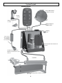
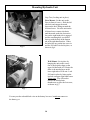
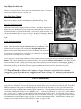
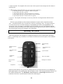
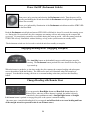
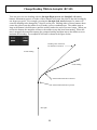
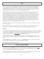
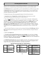
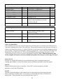
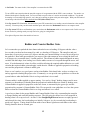
TR-1 Gold
Owner’s Manual
906-2000-00
RevH 101507
Thank You
Your purchase of this TR-1 Gold outboard management system enters you in the
prestigious fraternity of anglers who count on TR-1 to control their outboard kickers.
TR-1 Autopilots is dedicated to creating the finest controls and guidance systems for the
best in boating and fishing.
TR-1 Gold represents that effort. Enjoy your best fishing partner ever. We’re sure you will
agree it is worth its weight in GOLD.
Table of Contents
Safety & Cautions
Parts List
Specifications
Preparation
System Layout
Tools
Installation of E-H Unit (Pump)
Installation of Sensor Ball (Compass)
Installation of Deckmount/ Tach
Installation of Handheld/Remote
Verify Connections
Battery Connections
Connect & Fill Hydraulic System
GPS Connections System Functions and Features
Operating the System
Power On/Off (Deckmount)
Engaging Heading Hold
Change Heading with Remote Steer
Change Heading with RCAH (Changing Heading while in Autopilot)
GPS Steering
Setting North
Course overground
Steer to Waypoint
Orbit Waypoint
Cloverleaf Pattern
Search Pattern
Step Turns, Change Heading with
Circles, Change heading with
Reverse
MOB, change heading with
Idle/Resume
Throttle Up & Down
Zig-Zags, change heading with
Selecting Special Functions
Setup, How to make changes with
Setup Codes, Table of
Explanation of Codes
Adjusting Your Autopilot (Tuning and Setup)
Rudder and Counter Rudder Gain
Trouble Shooting Guide
Page 3
Page 4 & 5
Page 6
Page 6 & 7
Page 8
Page 9
Page 9 & 10
Page 11 &12
Page 13
Page 14
Page 14
Page 14
Page 15
Page 18
Page 19
Page 20
Page 21
Page 21
Page 21
Page 22
Page 23
Page 23
Page 23
Page 24
Page 24
Page 24
Page 25
Page 26
Page 26
Page 26
Page 26
Page 27
Page 27
Page 27
Page 28
Page 29
Page 30 & 31
Page 31 & 32
Pages 33-35
Pages 35-37
Page 39
2
Rev.H 101507
Safety
You are responsible for the safe and prudent operation of your vessel.
Your TR-1 Gold Autopilot is a tool that will enhance your capability to
operate your boat and catch fish. It does not relieve you from the
responsibility for safe operation of your vessel. You must avoid hazards
to navigation and never leave the helm unattended.
You must always be prepared to promptly regain manual control of your kicker. The
autopilot and the throttle actuators can fail hard over. Learn to operate your autopilot on
calm and hazard free open water.
In case the autopilot becomes inoperable, remove the in line fuse from the battery power
cable.
The steering cylinder can be removed from its mounting bracket on the outboard in case
of hydraulic jamming.
Removing the actuating link between the stepper motor and the carburetor butterfly
crank can disable the electric throttle.
Caution:
Before drilling holes in your boat, be sure you know what you are drilling into.
Watch out for fuel tanks, electrical cables, and hydraulic hoses.
Do not run your pilot with the outboard hard on the steering stops for any
extended time or you will burn out the pump motor.
Be sure to leave the system in Standby mode when Autopilot is not in use, or if
the kicker motor is not running.
We recommend you use only BioSOY hydraulic fluid in your autopilot hydraulics.
Keep your hands out of the outboard steering hinge area, the autopilot may steer the
motor and smash (or worse) your fingers.
3
TR-1 Gold Autopilot System Parts List
Electro-Hydraulic unit……………….…….
120-2100-00
Kinked tubing with tie wrap……………….
3 ea. Truss head machine screws #8-32x 3/4
3 ea. Lock washer nuts #8-32………………
3 ea. Truss head sheet metal screws #8 x 3/4
Sensor Ball Unit……………………………….……..
120-2200-00
Sensor Ball Bracket ………………………………….
3 ea. Pan head machine screws #8-32 x 1”…………
3 ea. Lock washer nuts #8-32…………………………
3 ea. Pan head sheet metal screws #8 x 1”…………
Sensor Ball Capture Cage...………………………….
Deck Mount Switch/Tach …………………………
120-2215-00
4
Handheld/Remote Unit...………………………….
120-2020-00
Cylinder Mounting Kit…………………
(Motor Specific)
18 feet Hydraulic Hose…………………………………
120-0013-01
Steering Cylinder………………………………………...
120-0900-00
Throttle Actuator ( Motor Specific)……………………….
1 pt. Hydraulic Fluid
120-0001-01(Bio-Soy)………………………………
5
5
TR-1 Gold Specifications
E-H unit
6.5”H x 7” W x 5” D
Sensor Ball
3.6” Dia.
Cable length 18’
Remote
5”x 2.5”x 1” Cable length 18’
Deckmount/Tach
5/8”x 2”
Cable length 6’
Battery Cable
Cable length 9’
Fluid
1 pt.
BioSOY Oil
Supply Voltage
11.5 – 14.0
VDC
Maximum Current
12
Amperes
Inline Fuse
ATO 20 Amp
Operating Ambient Temperature
20 – 120 deg F
8 lb
2 lb
1 lb
1 lb
Introduction
This manual comprises two major sections. The first section is a guide to installation of
the “onboard” components of the autopilot system on your boat. The second section is a
guide to adjusting and operating your system. Installation instructions for the throttle
actuator and steering cylinder are motor specific and are provided in separate manuals.
Preparation
You will be hard mounting three autopilot components in your boat: 1) The Electrohydraulic
Unit. 2) The Deckmount switch. 3) The Sensor ball. These components are shown in relation
to each other and to the engine mounted components in the System Layout diagram on page 8.
As indicated by this diagram, the Electrohydraulic unit and the Deckmount switch are to be
located near the kicker and the Sensor ball is to be located FORWARD OF THE CENTER
OF YOUR BOAT
Spend some time to figure out where you are going to mount all of the components before you
mount any of them. Place the components where you expect to mount them and verify you
have access to and routes for the cables and hoses that connect the components.
x Mounting Screws
Mounting screws are provided for through and blind hole applications. You may choose
to drill and tap the mounting surface.
SCREW
TAP DRILL
TAP
#8 – 32 machine
#29 .136 dia
#8 –32
#8 – 32 machine
CLEARANCE
PILOT
3/16
#8 sheet metal
1/8
6
6
x Access
The Electrohydraulic Unit is the place where all the components connect together and the place where
fluid is added and fluid level is checked. Leave room for service loops in the cables and hoses.
The Deckmount switch should be easy to reach with your free hand when your other hand is on the
kicker tiller. This can be done after the initial turn on blinking setup is complete. In case of an
emergency, quick access to the deckmount switch is a good idea, by pressing the button once it will
take the autopilot to standby, allowing you to take control of the tiller handle. Pressing the button
again will return it to autopilot mode.
If you intend to hook up to GPS, the connection between the GPS and the autopilot is made at the
Sensor ball and the NMEA 0183 output on your GPS.
x Protection
Locate the Electrohydraulic unit and Sensor ball in places where they will not get submerged or
exposed to wash down.
Use a quality electrical insuating grease compound on all electrical connections (Dow Corning
#4) except the orange connectors # 1,2,3, & 4.
x Moving Parts
Hoses and cables that connect the Electrohydraulic unit to the engine mounted components
need to be free from binding and kinking. Be sure to remember your kicker moves up and down
on the lift bracket, tilts up and down, and steers lock to lock.
x Hose Length
Try to keep the hose length between the steering cylinder and the Electrohydraulic unit short. But
leave enough length for movement of Kicker (See note above on moving Parts).
x Magnetic Environment
The Sensor ball has a compass in it. Do not mount the ball near magnetic materials, magnets
(speakers and electric motors), or high current carrying wires. Small, vehicle fixed, magnetic
disturbances can be calibrated out, but moveable or changing magnetic disturbances such as anchors,
anchor chain, and wiper motors should be kept at least 24” away. A common problem is to have
mounted the ball near a glove box, and then someone puts tools in the glove box. Keep the Sensor
ball away from Air Ride seats.
x Strain Relief and Cable Protection
Do not let the connectors on the Electrohydraulic unit be the sole support for the cables connected to
them. Use the tie wraps to tie the cables down to the Electrohydraulic frame. There are several holes
in the sheet metal frame provided for this purpose.
Don’t run cables and hoses over sharp edges. Use grommets in through holes to protect the cables.
7
7
System Layout
Handheld/Remote
Sensor Ball: Mount
in front 1/2 of boat.
Throttle
Actuator
Mounts on carburetor
on motor.
GPS connection
NMEA 0183
1
2
3
Battery
12V
4
Tach sensor
wire:Attaches
to spark plug
wire on kicker.
Electrohydraulic Unit: Mount near
transom.
Deckmount On/Off switch:
Mounts near kicker motor, near
transom.
Cylinder
Cylinder Mounting Bracket: Mounts on Motor
lower end.
8
Tools
You should gather the following tools before beginning installation. See throttle and cylinder
supplements for any additional tools that may be needed for your application.
Tools
Power Drill
#1 Phillips screw driver
.125 (1/8) or 3.17 mm dia. drill
.469 (15/32) or 11.90 mm dia. drill
Roll of masking tape
Rags
Knife
Pliers
Silicone RTV
Loctite or similar product
Electrical grease compound
(Dow Corning #4)
Fig .4
Installation of The Electro-Hydraulic Unit
Please read the complete instructions thoroughly before starting your installation. If
you have any questions call our Tech Support line. 1-800-588-7655
Locate the Electro-Hydraulic unit where it
it will not be subjected to water submersion
or spray from wash down.
Step one (Template)
Fig. 5
Find the mounting template in your autopilot
documentation package. Use the wall or floor
section of the template as needed. Decide which
screw type you need. Hold the template in the
place with tape and drill right through it in the
three indicated locations. See fig.5. Remove
template and install screws in the indicated
locations on template. Tighten these 2 screws
down to 3/32” from the surface to allow enough
space for the bracket on the pump to slide behind
the screw.
9
9
Mounting Hydraulic Unit
Step Two (Locking unit in place)
Fig. 6
Floor Mount: Set the unit on the
floor in front of screws. Slide the left
side back and engage the notch
between the hose fittings around the
left hand screw. Pivot the unit on the
left hand screw counter clockwise
until the notch under the electronics
box on the right hand side is engaged
and the remaining hole you drilled
lines up with the hole in the bottom
tab of the right hand bracket. When
the holes line up, put the last screw in
and the E-H unit is locked in place, as
shown in fig.6.
Wall Mount: Set in place by
hanging the unit on the screws.
One is the keyhole shape on the
upper left backside of E-H unit; the
other is the notched area on the
lower right side of E-H unit. Lock
E-H unit in place by lining up the
last hole on upper right hand corner.
Please note: You will need to
remove the black plastic
thumbscrew to place the last screw,
as shown in fig.7
Fig. 7
You may run the red and black wires to the battery box now, but do not connect to
the battery yet.
10
10
Installation of the Sensor Ball
The Sensor (Compass) Ball needs to be mounted forward of the center of your boat. Make sure
you mount it away from magnetic disturbances (stereo speakers, wiper motors, anchors). You
will need to calibrate your compass on the water after installation of system and before you use
the autopilot.
Step one (Mounting the Sensor Ball)
Hold the mounting bracket in the desired
position and drill through the holes into the
mounting surface. (Be sure that the wire
coming out of the ball can exit the ball
straight down.) Tap if necessary. Install and
tighten the three mounting screws as shown
in fig.8-a
If you need to make a paper template for a
drill pattern: The mounting holes are equally
spaced on a 1.224 inch radius circle.
Fig. 8-a
Step two (Placing ball in bracket)
Place the ball, wires down, into the
bracket and capture it by snapping the
cage over the ball, sliding the tips of the
cage between the ball and the legs of the
bracket. Do the two legs without the
thumbscrew first. Rotate cage upwards to
catch the bracket with the thumbscrew.
See fig. 8-b
Fig. 8-b
11
Step 3 (Adjusting Sensor Ball)
Readjust the ball if necessary and fix
it in position by tightening the
thumbscrew. See Fig 9-A. Make
sure that the wires from the Sensor
Ball are pointing straight down out
the bottom; otherwise the sensor ball
will not work properly. See Fig. 9-B
Fig. 9-A
Fig. 10-a
Fig. 9-B
Note: It is important to match
your ECU wiring configuration
to the picture. Just remember
to always plug into matching
numbers from the wire to the
ECU.
Fig. 10-b
Run the wire back to the E-H unit. The wire connector from the Sensor Ball is labeled number
4. It connects to the E-H unit at connector 4, as shown in fig.10-a or 10-b. (this will depend on
your ECU wiring configuration). When you plug in the connectors, the wires go at about a 45qangle left of the numbers on the E-H unit (fig. 10-a) or at a 90° angle for fig 10-b. Feel the
connectors start before pushing it down.
12
12
Installation of the Deckmount and Tach
Step One: (Deckmount)
If the material you wish to mount the Deckmount
switch in is less than ¼” thick: Drill a hole 15/32
Diameter perpendicular to the surface. Unscrew
the bezel from the switch and leave one washer on
the neck. Put the switch button, with washer,
through the hole from below. Screw the bezel on
to the top and your done. Refer to Fig.11
Fig. 11
If the surface you want to mount the Deckmount on
is thicker than ¼ inch, Drill a 19/32 hole through
the surface. Unscrew the bezel from the top of the
switch and remove the washers. Slide the switch
all the way through the hole from the backside of
the panel. Apply some silicone sealer/adhesive to
the barrel of the switch. Screw the bezel, with or
without a washer back onto the switch and slide the
switch back into the hole. It may be necessary to
tape or otherwise hold the switch in place until the
sealer/adhesive sets. Alternatively, you can make
a custom sheet metal bezel/mounting bracket for
the switch.
Note: Route the cable for the tach on the
opposite side of the kicker motor that you route
the throttle actuator wire.
Step Two (Tach)
Fig. 11-A
The Tach is the portion of the cable with a white antenna
end. The antenna end needs to be installed into your
outboard motor. The wire connector from the deck
mount/Tach switch is labeled number 1. It connects to the
E-H unit at connector number 1. Route the Tach portion of
the wire from the E-H unit back to the motor. Remove the
outboard cover. Route the cable through the grommets on
the front of your motor, then route the cable around the
motor to the spark plug wires. You will need to lay the
white or antenna end of the cable along side of one of the
spark plug wires in your motor. Keep the antenna end at
least 1” from either end of spark plug wire. Do not
stick the end of the wire into the boot of the spark plug
wire. Use tie-wraps to attach the antenna end of cable to the
Spark plug wire. (Fig. 11-A)
(After installation of your Autopilot, you will need to verify
your tach. Please refer to page 31, paragraph 2 for more
information).
13
Installation of the Handheld/Remote
Connect the Remote cable to the ECU unit at
connector number 3. Strain Relieve the cable.
One place to do this is the bottom right hand side
of the ECU unit. See Fig. 12. This will help
protect the Remote cable from being pulled out
of the connector on the ECU unit and possibly
damaging unit. If you need to drill a hole in the
boat for the cable be sure to put a grommet in the
hole to protect cable from the sharp edges.
Fig. 12
Installation of the Cylinder Kit and Throttle Actuator
Refer to the manuals supplied with the throttle and steering cylinder kits, and install these parts
before continuing with the procedures that follow. If you do not use the throttle actuator, it is
recommended that you coat #2 pico connector with a grease to protect it from corrosion.
Connections
At this point, all electrical connections to the
Electrohydraulic unit are complete. Some
Fig.13-a
ECU wiring configurations are slightly
different see fig. 13-a and fig.
13-b for your variation. Verify these
connections as follows:
Deck mount #1
Throttle #2
Handheld #3
Sensor Ball #4
To
To
To
To
ECU connector #1
ECU connector #2
ECU connector #3
ECU connector #4
Fig.13-b
Battery Connection Installation
Now hook up the battery connections. We recommend that you
connect the battery cable directly to the battery. Connect the
ground side first. Connect the black wire to negative (-) side of
the battery. Connect the orange wire to the positive (+) battery
terminal.
Note: Do not be alarmed if connection sparks when connected to
battery, you are charging a capacitor inside the unit.
Do not cut out or eliminate the fuse portion on your battery
cable, it is there to protect your system and may void your
warranty if removed.
If you unplug the battery cable be sure to replace the tie wrap
around connectors to prevent them from separating.
14
Connect and Fill the Hydraulic System
Before you start………
x As with all hydraulic systems, it is very important to keep any dirt or debris from entering
the system.
x If you haven’t already, loosen the steering tension adjustment on your motor to the minimum
setting. The motor should turn very easily. (If necessary refer to your outboard motor’s
owner’s manual).
x The fittings in the electro hydraulic unit (Pump unit) and the Cylinder are barbed hose fittings.
It is important that you push the hose completely over the barbs. Use some fluid to lube the inside
of hose before pushing them on. It will make the process slightly easier.
x This process may be a little messy so keep a few rags handy. Safety glasses are also a good idea.
Step One
Remove the Left side of the kinked clear shipping tube from
the E-H unit. Keep the kinked clear tube (with the tie wrap)
on the Right barbed fitting (It will act as a plug).Fig.A
Step Two
Run a continuous section of black rubber hose from the Left
E-H fitting, out the back of the boat to the cylinder and back
into the boat to the pump. Do not cut the hose at this time.
See.Fig. B
Fig A
Fig. A
Fig. B
15
15
Step Three
Arrange the hose at the cylinder end so that none will kink and they
are hanging free. Put a piece of tape on the right hose at the cylinder
end to identify it. You will need to know this when it’s time to
connect the hose to the cylinder. See Fig.14.
Step Four
Fig. 14
Get into the boat close to the E-H unit. Bring the Remote Handheld,
fluid, and some rags. Remove the screw that locks the E-H unit in
place so that you can move the unit around. Remove the tank plug by
unscrewing counterclockwise and remove. Note the tank has two
fluid level lines on it. The upper line is the full line and the lower line
is the low fluid line.
Step Five ( Purge Air)
Fig. 15
Fig. 15-a
Take the open end of the continuous loop of black hose,
and insert it into the tank as shown in Fig. 15. Be sure
that the other end of black hose is secure on the left
barbed fitting on the E-H unit. Also make sure that
the clear kinked hose is also secure on the right barbed
fitting. (Use of tie wraps may be necessary)
Turn the pilot on by momentarily pressing and releasing
the deckmount switch. When the Stby LED quits
blinking, press the top button on the remote (Auto/Stby)
the Auto Led will be lit. Holding the tube in the tank
press the Left Straight Arrow. Refer to fig. 15. The
fluid level will go down. Let the button up and place
system in STBY when the fluid is low and refill the
tank. (Do not press the Straight Right Arrow Button,
you will blow the clear tube off the right side and
create a hydraulic fluid mess)
You may need to fill the tank several times. Keep the
hose submerged in the tank fluid and keep pumping until bubbles stop
appearing in the tank.
Turn the system to standby by momentarily pressing the top
button (AUTO/STBY) on the handheld. Turn the unit off by
pushing in the deckmount button and hold until the lights are
out (about to the count of 5). Remove the hose from the tank,
keeping your thumb over hose to prevent air from entering or
losing fluid. Insert the tank plug, fitting it securely into the top
of tank. Tilt the fitting end of the E-H unit back and remove
the kinked shipping hose from the E-H. Now push the rubber
hose onto the right fitting pushing firmly until fully engaged
over barbs. Install the Two (2) Hose clamps over the hose and
barbed fittings at the manifold and tighten. See Figure 15-a.
You will need the clear shipping tube again in the next step
so don’t throw it away yet.
16
Step Six (Fill Cylinder)
Fig. 16
You will need the motor in the down position and
the cylinder fittings pointing straight up.
Disconnect the rod end of the cylinder from its
mount. Find the kinked piece of tubing that you
removed in step one. Remove the tie wrap and cut
the tubing in half. Push one half on each cylinder
barbed fitting. Open the fluid bottle. Insert pieces
of tubing into the fluid. They need to go to the
bottom of the bottle. Now hold the tubing in the
bottle with one hand and pull and push the rod in
and out of the cylinder until you stop seeing air
bubbles in the hose. Refer to fig. 16
Slide the rod into the cylinder as far as it will go. Now remove the short clear hose from the cylinder and
drain the fluid from the tubing into the bottle. Be sure both cylinder fittings are full to the top. Point the
rod end of the cylinder toward the pin that engages it but leave it pushed into the cylinder.
Step Seven (Correctly connect the hose)
At the cylinder, kink the black hose (bend it
over sharply and use a tie wrap to pinch hose
shut). See Fig. 17. Cut the hose as shown just
above the tie wrap and keep a thumb over the
right side to keep the fluid in the hose. Keep
the hose full to the brim and push the right
hose (hose that has tape) onto the right cylinder
fitting as shown in Fig.17-A
Cut the tie wrap on the left hose and insert it on
the left fitting on the cylinder as shown in
Fig.17-B. Reconnect the cylinder rod end.
Fig. 17
Fig. 17-A
Fig. 17-B
17
17
Step Eight (Check hose fit)
Check to see that the hose is free to move back and forth with motor. Tie wrap as
necessary to hold hose in place. See Fig. 18
Step Nine (Hose Clamp)
Place hose clamps over hose and fittings at cylinder end. Fig. 18-a
Step Ten (Top off the system)
Manually turn the motor back and forth several times. Air bubbles trapped in the
tubing may cause the fluid level in the tank to surge when the tiller is moved fast.
The more the tiller is cycled back and forth, the more air is purged from lines. Top
off the tank with fluid when the surge is reduced. Replace the tank plug. Remount
the pump unit following the instructions on page 10, making sure all screws are
tight.
Verify Proper Installation
Press the deck mount switch to turn the system on. Put the unit in AUTO
mode. Press and hold the Straight Left Arrow button on the Remote. The
kicker will steer to the port. Press and hold the Straight Right Arrow
button on the Remote and the kicker will steer to starboard. Turn the motor
several times in each direction to verify that hose connections are tight and
that you have no binding of hoses or cables.
Get in position to see the kicker carburetor and the throttle actuator you installed, then press and hold the Up Arrow
button. The actuator should open the carburetor throttle. Press and hold the Down Arrow button. The actuator should
run the carburetor to idle. Pushing and releasing these buttons quickly moves the throttle by small amounts. Holding
them down changes the throttle by large amounts. Move the throttle to mid-travel and then press the IDLE/RES button.
The throttle should go to idle. Press the button again and the throttle should go back to the mid-travel position.
!!!! You will need to calibrate the Compass of your Autopilot, and will need to tune the
Autopilot to your boat and motor configuration. Please see page 33, adjusting your Autopilot
for Heading Hold operations on your Boat.
GPS Connections
Check to see that your GPS transmits NMEA 0183 messages $GPRMB (RMB),and $GPRMC (RMC) before you hook
your GPS to the autopilot. These are the messages the autopilot must receive in order to steer with the GPS. Your GPS
NMEA output wires will usually be bundled with other conductors in the GPS cables. Look in your GPS manual for
instructions relating to NMEA output from the GPS to other devices. The GPS manual should identify two wires that
are named something like NMEA out (+) and NMEA out (-). Connect the NMEA out (+) to the red (+) and the NMEA
out (-) to the white (-) conductors in the stub cable with the blue tip at the Sensor ball. You will need to strip some of
the jacket from the blue tipped cable in order to get to the red and white conductors. 22 or 24 gage twisted pair wiring is
recommended for connecting this circuit. (See page 23 for more information on GPS.) You will need to calibrate your
compass and Set North in order for GPS functions to work. See pages 23 & 35
18
Introduction to Operation and Adjustments
This section of this document provides you with information that will let you take advantage of
your TR-1 Gold autopilots' capabilities. We have made every effort to minimize the pain in
getting you up to speed as a user of the TR-1, however, programmable devices such as your TR1, are often difficult to learn to use and to program. We recommend that you do not take your
fishing tackle with you on your first trip with your new autopilot. Take a few hours on a nice
day to get your system setup and familiarize yourself with its operation, then your first fishing
trip with the unit will really have you smiling.
This manual is laid out in sections that are, as best we can make them, self contained. We start
with the features and functions available and fundamentals of how the system works, then how to
operate the basic functions, and finally how to get into the fine adjustments.
Some of you will find that this manual is lacking in depth and clarity, and for this we apologize.
Please do not hesitate to call us for interpretation and other help you may need.
System Functions And Features
The TR-1 is, at its core, a heading hold autopilot. It steers the kicker to maintain a constant
magnetic heading. The autopilot measures magnetic heading with a flux gate compass and
receives rate of turn information from a vibrating beam rate sensor (gyroscope). The autopilot
computer forms a rudder rate command from a combination of the compass, gyro, and engine
tachometer signals. This rudder rate command is calculated and sent to the pump controller in
the electrohydraulic unit electronics 20 times each second. The pump control electronics
servos the pumping speed and direction to match the rudder rate command from the autopilot.
The autopilot is designed to disconnect from the steering cylinder when it is off or in standby.
It does this with a bypass valve that shunts fluid from the steering cylinder around the pump
when the bypass valve is open.
Beyond the basic heading hold function, the autopilot provides for several other modes of
automatic and manually controlled steering functions. These are listed below.
1. Rudder Command / Attitude Hold (RCAH). RCAH is the primary means for changing the
boats heading manually.
2. Remote steer. Remote steering is used for electrically steering the kicker without feedback
from the gyro or compass.
3. Step turns. The autopilot will execute predetermined fixed angle turns in this mode.
4. Circles. The autopilot will turn in circles of predetermined duration.
5. Zigzags. The autopilot will steer a zigzag course with predetermined angle and duration.
19
6. Man Overboard. The autopilot will execute a turn to the reciprocal course and pass near the maneuver
initiation point.
7. GPS steering. (Some GPS units may not support these features.)
7a. The autopilot will steer to a waypoint or series of waypoints.
7b. The autopilot will orbit a waypoint.
7c. The autopilot will steer a 3 leaf clover pattern over a waypoint.
7d. The autopilot will steer a spiral search pattern around a waypoint.
7e. The autopilot will steer to constant course over ground.
8. Reverse. The autopilot will attempt to execute any of the above steering functions while the boat is
backing.
The TR-1 system includes an electric throttle mechanism for remote control of the kicker throttle
valve. The throttle butterfly valve is actuated by a lead screw and stepper motor. The stepper advances
or retracts the lead screw in 1/1000 inch steps as commanded by the remote control pushbuttons. On
system power down, the stepper is commanded to take the butterfly valve to its' closed throttle position.
The throttle system has an Idle/Resume feature that provides for single button push reduction of throttle to
idle and subsequent button push resumption of the initial RPM.
Operating The System
Most of the operation of the autopilot is accomplished through the remote control and the deckmount
switch. To make things easy to talk about we will name the buttons as shown in the picture of the handheld/
remote below.
Autopilot/Standby
Button
Straight Left Arrow
Button
Straight Right Arrow
Button
GPS (Select Load)
Button
Up Arrow Button
Idle/Resume
Button
Down Arrow Button
Bent Left Arrow
Button
Bent Right Arrow Button
Setup Button
Almost all of the buttons in the systems have multiple functions, and many functions are accomplished by
button push sequences or by pushing more than one button at a time. The steering and throttle modes are not
all available simultaneously. The Idle/Resume , Bent Left Arrow, and Bent Right Arrow buttons are
sometimes referred to as “special function” buttons in the following text.
20
Power On/Off (Deckmount Switch)
Turn power on by pressing and releasing the Deckmount switch. Turn the power off by
pressing and holding the switch down until the Deckmount switch light has extinguished
(about four seconds).
Power on is indicated by illumination of the Deckmount switch button and the STBY LED
on the Hand Held.
Both the Deckmount switch light and remote STBY LED will blink for about 30 seconds after turning power
on. During this 30-second time, the pilot computers are running self-test and starting up the compass and
gyroscope. No autopiloting operations are available during this start up period. After the startup period the
STBY LED will stay illuminated, without blinking, as long as the system remains in standby mode.
The deckmount switch can also be used to switch the unit from standby to autopilot.
Engaging Heading Hold (Engaging Autopilot)
The Auto/Stby button on the handheld engages and disengages autopilot
steering. The Deckmount button performs the same function after the pilot
is powered up.
When the button is pushed to go into Auto mode, the pilot captures the compass heading and subsequent
moves the rudder to hold that heading. The LED next to Auto will illuminate when The autopilot is
engaged. You should be steering your boat on a constant heading at the time you Press the Auto/Stby
button.
Change Heading with Remote Steer
If you program the Bent Right Arrow and Bent Left Arrow buttons for
Remote Steer, when one of these buttons is pushed, the rudder is directly
controlled by these pushbuttons until a Straight Right Arrow or Straight
Left Arrow button is pushed to reengage the pilot or the system is returned standby.
(In remote steer, (autopilot0 heading hold is not engaged and will not lock on to a new heading until one
of the straight arrows are pressed to take it out of remote steer.)
21
Change
Heading
with
RCAH(RCAH)
Change
Heading
While in
Autopilot
You can steer to a new heading with the Straight Right Arrow and Straight Left Arrow
buttons. Momentary presses of either of these buttons will cause the pilot to alter the heading by
one degree per press. For example, pressing the Straight Left Arrow button five times will
cause the heading to be changed by 5 degrees to the port. Holding either of these buttons down
causes the pilot to turn the rudder so as to make a port or starboard turn. The rudder turns as
long as the button is held down or until the rudder reaches the end of its travel range. When you
release the button, the autopilot will move the rudder to stop the boat from turning. When the
turn is stopped, the autopilot captures the compass heading and then moves the rudder so as to
maintain this heading. An example RCAH turn is shown in the figure below.
Heading when starboard
RCAH button released
Initial heading
Final heading
Starboard RCAH button released
Starboard RCAH button pressed
Boat path
22
22
GPS Steering
GPS
The GPS steering functions are not guaranteed to work with all GPS systems. Each manufacturer of GPS equipment
puts his own spin on how to assemble the data on the NMEA data bus. Sometimes the data on the bus will not
conform to the needs of the autopilot. The autopilot expects to see, at least, the NMEA data sentences $GPRMB
and $GPRMC at 4800 baud. These sentences are the minimum recommended data to be transmitted when there is
an active waypoint. Some GPS systems do not conform to this NMEA specification.
Almost all GPS systems truncate the cross track error data to 0.01 NM resolution, this means that the autopilot
cannot be expected to stay on track any closer than 60 to 120 feet. There is a large discrepancy between
manufacturers in how they warn the user when the navigation fix is compromised. Some systems alert the NMEA
bus listener immediately upon position fix loss but wait 30 seconds to a minute to warn the operator on the GPS
display. This is disconcerting to the user because his autopilot drops out (The autopilot stops using the GPS
steering command immediately upon receiving a warning from the navigator.) of GPS steering and there is often
no indication on the GPS display that anything is wrong with the GPS. Some manufactures wait 30 seconds to
alert the user via the display and the devices on the NMEA’S data bus when the position fix is broken. The worst
performance in all the GPS units we have tested occurs when a satellite is occluded by the horizon; we have seen
steering errors on the order of several hundred feet in these situations.
The autopilot cannot fix steering errors that are GPS generated. Keep an eye on where you are going when you couple
the GPS to the autopilot.
When the autopilot is taking steering commands from the GPS, the GPS (Select Load) LED will be lit solid. If the
autopilot detects a GPS problem it will blink this LED. Press any button to extinguish the blinking LED.
Set North
To run a GPS course requires that the autopilot compass is in agreement with the GPS’s course estimate. You need to set
North with the pilot in standby mode. Do not set North except in calm sea’s and un-accelerated conditions. You should
be running at a reasonably high speed, it won’t hurt to be running on plane with your main engine. With your GPS
turned on and setup code 48 selected, press and hold the GPS (Select Load) button.
If the Up Arrow LED illuminates, this means that your GPS connection is not sending course information to the
autopilot correctly. You must point your boat north and then press and release the Deckmount switch to set compass
north.
If the Up Arrow LED does not illuminate, press and release the Deckmount switch to set compass north. In this case
you do not need to be pointing north-you only need to be going in a straight line.
Your pilot will power down after north has been set.
Course Overground Hold
If you press and release the GPS (Select Load) button when the autopilot is in heading hold and the GPS does not have
an active route, the pilot will maintain the GPS course over ground instead of the magnetic heading. Be aware that the
course over ground calculated by the GPS is erratic at low speeds.
All the special function and turn buttons will continue to behave as if you are in normal heading hold. If you use any of
the normal turning buttons, go to waypoint and course over ground hold are terminated.
23
Steer To Waypoints (GPS Steering)
If you press and release the GPS (Select Load) button when the autopilot is in heading hold and the GPS
has an active route, the pilot will steer to the selected waypoint.
If you are more than 1000 ft. off the courseline the pilot will steer directly at the waypoint and not try to
remove crosstrack error.
Return to heading hold by pressing one of the Straight Arrow buttons.
Orbit Waypoint (GPS Steering)
The autopilot will orbit the waypoint you have activated in your GPS, with the waypoint to your starboard
side if you press the Bent Right Arrow button when the GPS (Select Load) LED is lit and the special
function Orbit Wpt has been enabled. The waypoint will be on your port side if you use the Bent Left
Arrow button.
The orbital radius is the distance from the waypoint at the time you press one of the bent arrow buttons.
Return to heading hold by pressing one of the Straight Arrow buttons.
Three Leaf Clover Pattern (GPS Steering)
The cloverleaf pattern is intended for use when you wish to repeatedly pass over a point where you think
The cloverleaf pattern is intended for use when you wish to repeatedly pass over a point where you think
fish may be holding. You must mark the location of the cloverleaf stem with a waypoint in your GPS.
fish may be holding. You must mark the location of the cloverleaf stem with a waypoint in your GPS.
Once
Oncethe
thewaypoint
waypointisissaved,
saved,select
select“go
“goto”
to”this
thiswaypoint
waypointon
onyour
yourGPS.
GPS. From
Fromheading
headinghold,
hold,press
pressand
and
release
the
GPS
(Select
Load)
button.
The
pilot
will
start
maneuvering
toward
the
waypoint.
If
you
release the GPS (Select Load) button. The pilot will start maneuvering toward the waypoint. If youhave
have
selected
pattern
as the
function
for the
Arrow
buttons,
pressing
eithereither
Bent Bent
Arrow
selectedclover
3 Leafleaf
Clover
pattern
asspecial
the special
function
forBent
the Bent
Arrow
buttons,
pressing
button
startwill
the boat
cloverleaf
pattern. pattern.
If you used
the used
Bentthe
Right
Arrow
cloverleaf
Arrowwill
button
start on
thethe
boat
on the cloverleaf
If you
Bent
Rightbutton
Arrowthe
button
the
will
be
traversed
by
always
turning
to
port.
The
length
of
one
of
the
cloverleaves
is
programmed
with
cloverleaf will be traversed by always turning to starboard, the other Bent Arrow button will cause
the
setup
code
29.traversed
It is adjustable
in length
from to
500ft
6000
ft in 100
ft increments.
pattern
to be
while always
turning
port.to The
length
of one
of the cloverleaf is programmed
with setup code 28. It is adjustable in length from 500 ft. to 6000 ft. in 100 ft. increments.
Return to heading hold by pressing one of the
Straight Arrow buttons. An example of the CloverLeaf pattern is shown in the figure to the left.
24 24
Search Pattern (GPS Steering)
To do an outward spiraling search from a waypoint, setup the special function buttons for search
patterns. (See page 28 Selecting Special Functions) When you are near the waypoint you want
to search from, select “go to” this waypoint on your GPS. With the pilot in heading hold, press
and release the GPS (Select Load) button and then press and release one of the Bent Arrow
buttons. If you pressed the Bent Right Arrow button, the waypoint will remain on your
starboard side as the spiral search unwinds. The spacing between the spiral laps is set with setup
code 249.
Return to heading hold by pressing one of the straight arrow buttons. An example of the search
pattern is shown in the figure below.
25
Reverse
The autopilot will attempt to perform any of its steering functions when the boat is backing in
reverse gear. To engage the system in reverse: 1) Start from Standby. 2) Press and hold the GPS
(REV) button. 3) Press and release the Auto/Stby button. 4) Release the GPS (REV) button.
Circles
If you program the Bent Right Arrow and Bent Left Arrow buttons for Circles, pressing the
Bent Right Arrow button will cause your boat to be driven in a clockwise (from above) circle
with a lap time between 1 and 90 minutes (programmable). The Bent Left Arrow button will
cause counterclockwise turns. You can exit the circle and run straight anytime by pressing either
the Straight Right Arrow or Straight Left Arrow button.
Step Turns
If you program the Bent Right Arrow and Bent Left Arrow buttons for Steps, when one
of these buttons is pushed, the pilot will execute a port or starboard turn. The turn will
terminate when the programmed step angle is reached. The step angles are programmable
from 1 to 90 degrees. Multiple pushes of these buttons will result in a turn through an angle
equal to the sum of the angles per push. For example, if you have programmed the pilot for 10
degree steps, five pushes of the Bent Right Arrow button will turn you 50 degrees to starboard.
180 degrees is the maximum turn sum.
Changing Heading With MOB
The Man Overboard (MOB) function causes the boat to turn to starboard for a while then turn to
port until the reciprocal course is established, with the goal of running alongside the point where
the MOB button was pushed. The boat path will be as shown in the figure below.
2626
Throttle
Up/Down
Throttle
Up/Down
Increase throttle by pressing the Up Arrow button. Decrease throttle by pressing the Down Arrow
button. The electric throttle runs in parallel with the tiller throttle, this means that you can't reduce
the RPM with the electric throttle if the tiller throttle is set high. It is best to always run with the tiller
throttle set to idle. Be careful to set the electric throttle and tiller throttle to closed position before starting
your outboard.
Idle/Resume
Feature
Idle/Resume
Automatic idle and resume is accomplished by pressing the Idle/Resume button. If the throttle is set
higher than idle, the Idle/ Resume function will take the engine to idle. If the throttle is sitting in the
idle position, the Idle/Resume function will return the throttle to the last "above idle" position. The
Idle/Resume button must be programmed to perform Idle/Resume and not MOB or Zigzags.
Change Change
Heading
Using
Zig-Zags
Heading
with
Zigzags
If you program the Idle/Resume button for Zigzags (other), then when you press the Idle/Resume
button the pilot will begin to zigzag about the heading you were on when you pressed the button. The
zigzag angle and period are both programmable. An example zigzag path is shown in the figure below.
Heading Hold
Boat Path
27
27
Selecting Special Functions
When you select special functions, by the methods described below, you are simply choosing which
function is to be executed by the pilot when you push one of the tree special function buttons.
The Idle/Resume button is programmable to provide either Idle/Resume or MOB or Zigzags (other).
The Bent Left Arrow button is programmable to provide either Steps or Circles or Remote Steer.
The Bent Right Arrow is used to program the pilot for waypoint Orbiting or clover leaf or search
steering in conjunction with your GPS.
To change the functions of these programmable buttons, follow the directions below.
1. Autopilot must be in Heading Hold or Standby Mode before selection process can start.
(AUTO LED solid on or STBY LED solid on. No other LED's on.)
2. Press and hold Setup Button. Three LED’s next to the numbers 1 through 9 will illuminated,
indicating which (3) special functions are programmed to operate. For example, if LED 2, 4, and 7
illuminate, your system is programmed to do: 1) Idle Resume when the Idle/Resume button is
pressed. 2) Step turns to port when the Left Bent Arrow button is pressed. 3) Step Turns to
starboard when the Bent Right Arrow button is pressed. 4) Orbit a waypoint clockwise when the
Bent Right Arrow button is pressed and the system is tracking a GPS signal. 5) Orbit a waypoint
clunterclockwise when the Bent Left Arrow button is pressed and the system is tracking a GPS
signal.
3. Select the Special Function you want to use by pressing and releasing the Idle/Resume and Left
Bent Arrow button until the appropriate LED's are lit. (See the Table below for Special Function
Indicators.)
4. Release the Setup Button.
5. To make the selected Special Functions into start up defaults: Press and release the Setup
button and verify the setup LED is lit. Then press and hold the GPS (Select Load) button. Verify
that the Load LED is lit. Then press and release the Deckmount switch, then release the GPS (Select
Load button). (This Locks in your selections)
6. To illuminate the keypad on the remote for nighttime operation: Press and hold setup and press
the up arrow. Repeat to turn the back light off. The down arrow will toggle the brightness of the
orange LEDs between bright and dim when the setup button is held down.
Special Function Indicator LED Numbers
GPS Steering
(GPS connection required)
1
MOB
4
Steps
2
Idle/Resume
5
Circles
7
Orbit Wpt.
3
Other
6
Remote Steer
8
3 Leaf Clover
9
Search
28
How to Make System Changes with Setup
1. Autopilot must be in Heading Hold or Standby Mode before selection process can start.
(AUTO LED solid on or STBY LED solid on. No other LED's on.)
2. Press and release the Setup Button. The Setup LED will illuminate to indicate the system is
ready to take setup commands (button pushes).
3. Make selection of the Setup Function you want to use by pressing and releasing the buttons
labeled 1 through 9 until the appropriate LED's are lit. (See the Table below for Setup Codes.)
4. Increase an adjustable parameter one step by each press of the Up Arrow button. When the
parameter is adjusted to its maximum value, the Up Arrow LED will light. The parameter is
adjusted and is in use by the autopilot immediately.
5. Decrease an adjustable parameter one step by each press of the Down Arrow button. When
the parameter is adjusted to its minimum value, the Down Arrow LED will light. The parameter
is adjusted and is in use by the autopilot immediately.
6. You can stay in Setup and adjust more than one parameter.
7. Compass Calibration, and resetting to factory defaults are setup conditions that take the
system over and restart the autopilot computer. The button sequences for their operation are
given in the Table of Setup Codes below.
8. To view the operating value of an adjustable parameter, enter its code per the Table of Setup
codes, then press and hold the GPS (Select Load) button. The LED on the Up Arrow button
will blink the number of tens the parameter is set to and the LED on the Down Arrow button
will blink the number of ones the parameter is set to. For example if the parameter is set to a
current value of 15, the Up Arrow LED will blink once and the Down Arrow LED will blink 5
times to indicate the parameter is set to 1 (blink) X 10 + 5 (blinks) X 1. Of course, when a
parameter is adjusted to its minimum or maximum value, the appropriate LED stays on solid per
4. and 5. above.
9. For temporary use of the adjusted parameters: Press and release the Setup button to exit the
setup mode.
10. To make the selected Special Functions into start up defaults: Press and release the Setup button
and verify the setup LED is lit. Then press and hold the GPS (Select Load) button. Verify that the Load
LED is lit. Then press and release the Deckmount switch, then release the GPS (Select Load button).
(This Locks in your selections)
29
Table of Setup Codes
Tachometer Codes
Setup Action
Code #
Range of Settings or Responses
Default
Stby Safety Monitor
349
2 settings on, off, defaults to on every power up
on
Tach on/off
34
2 settings on, off
on
Show RPM
36
Hold Down Select Load Button:
1000’s blink on up Arrow
100’s blink on down Arrow
Throttle Codes
Throttle Speed
24
1 lowest speed, 10 highest speed
5
Throttle Delay
25
1 least delay, 10 most delay
5
Hydraulic Codes
Reverse Hoses
259
2 settings normal up arrow lit, reverse down arrow lit
normal
Automated Setup Codes
Calibrate Compass
47
Hold Down Select Load Button, press and release Deckmount
Button to start Calibration Process
Load Factory Compass
49
Hold Down Select Load Button, press and release Deckmount
Button to reload factory Compass Calibration
Load Factory Pilot
59
Hold down Select Load Button, press and release Deckmount
Button to Reload Factory Pilot Settings
Special Function Setup Codes
Degrees per Step
6
10 choices/1,2,3,4,5,10,15,30,45,or 90 Degrees
15
Circle Time
7
10 choices/ 1,2,3,4,5,10,,15,30,45,or 90 Minutes
5
Zig-Zag Amplitude
8
10 choices 5 to 50 degrees by 5’s
30
Zig-Zag Period
9
20 choices 1 to 20 minutes by 1’s
3
MOB overshoot
28
1 most overshoot command, 40 most undershoot command
20
Cloverleaf Length
29
500 ft to 1000 ft by 50 ft increments
1000
Search Spacing
249
50 ft to 1000 ft by 50 ft increments
50
30
30
Navigation Function Codes
Navigation Function Codes
Setup Action
Setup
Action
Navigation
Gain
Navigation
Navigation Function
Gain GainCodes
Navigation
Trim
Navigation
Trim
Gain
Use
Synthetic
XTE
Setup Action
Use Synthetic
Change
Sign
ofXTE
XTE
Navigation
Gain
Change
Sign ofNorth
XTE
Use
Magnetic
Navigation
Trim Gain
UseNorth
Magnetic North
Set
Use
Synthetic XTE
Set North
Change Sign of XTE
Use
Magnetic
North
Enable
Checksums
Set
North
Enable
Checksums
Code #
Code
15 #
15
16
16
37
Code
#
37
18
15
18
39
16
39
48
37
48
18
39
347
48
347
Range of settings or Responses
Range
of settings
orgain
Responses
1 lowest
gain,
73 highest
lowest gain,
gain, 73
73 highest
highest gain
gain
11 lowest
lowest gain,
73 highest gain
21 settings
off
Rangeon,
of settings
or Responses
2 settings
settings on,
off
2
on,
off
1 lowest gain, 73 highest gain
2 settings
settings on,
on,off
off
12lowest
gain, 73
highest gain
2 settings
on,Select
off Load Button, press and
Hold
Down
2 settings on, off
release
Deckmount
Button
to set press
north and
Hold Down
Select Load
Button,
2See
settings
on,
off
Notes
code #48 Button to set north
release
Deckmount
22See
settings
on,
off
Notes
code
settings on,
off#48
Hold
Downon,
Select
2 settings
off Load Button, press and
release Deckmount Button to set north
See Notes code #48
2 settings on, off
Default
Default
42
42
49
49
off
Default
off
off
42
off
on
49
on
off
off
on
on
on
Fine Tuning
Codes
Enable
Checksums
347
on
Fine Tuning Codes
Seastate Filtering
1
1 least responsive steering, 5most
5
responsive
steering.
Seastate Filtering
1
1 least responsive
steering, 5most
5
Rudder
Gain Codes
2
1responsive
Lowest gain,
60 highest gain
22
steering.
Fine
Tuning
Rudder Gain
2
1 Lowest gain, 60 highest gain
22
Counter
Rudder
Gain
3
1
lowest
gain,
60
highest
gain
37
Seastate Filtering
1
1 least responsive steering, 5most
5
Counter Rudder Gain
3
1 lowest gain,
60 highest gain
37
responsive
steering.
Speed
Schedule
35
4
settings
1
aggressive,
2
moderate,
3
mild,
Rudder Gain
2
1 Lowest gain, 60 highest gain
224
4 weak
Speed Schedule
35
settings 1 aggressive, 2 moderate, 3 mild,
4
weak gain, 60 highest gain
Counter Rudder Gain
3
14lowest
37
Notes:
Code 1 Sea State Filter.
Speed
Schedule seems to be too active35in rough
4 settings
1 aggressive,
2 moderate,
3 mild,
IfNotes:
the Autopilot
water (the
kicker motor
is overactive)
but works4perfect in
Code
1.
weakFactory default sets this code at the top of its range (4)
calm water, adjusting the Sea State Filter may4help.
Seastate
adjustments
toward
least
responsive
slow
the heading
down.
of the timeat the the
Code
1.
which is most active (least active is 1) . Most of the time
you willresponse
want to run
withMost
this parameter
you
want toTo
rundecrease
with
thisthe
parameter
allsensitivity
the
waythe
at
the
top water
of
its range.
Seastate
adjustments
toward
least
responsive
slow
response
down.
of the
time
Notes:
top
ofwill
its range.
autopilots
inheading
rough
1) Press
andMost
release
[SETUP}on
the
you
will
want
to
run
with
this
parameter
all
the
way
at
the
top
of
its
range.
handheld, the setup LED will be lit. 2) Press the [IDLE/RES] button and light up the number 1 LED .
Codes1.15 & 16.
Code
3) Press the down arrow button to decrease the autopilots sensitivity. Note: When the autopilot is shut
The
best
way
to tunetoward
GPS tracking
is to startslow
with the
the heading
trim gainresponse
at its minimum
and set the
Codes
15
& 16.
Seastate
adjustments
down.is Most
thepage
time28, Step 5.
off, the autopilot
will returnleast
to itsresponsive
factory default
setting unless
the setting
savedofSee
coupling
gain
as
high
as
it
can
be
set
without
causing
oscillations
around
the
course
line
capture.
The
best
way
to
tune
GPS
tracking
is
to
start
with
the
trim
gain
at
its
minimum
and
set
the
you will want to run with this parameter all the way at the top of its range.
coupling gain as high as it can be set without causing oscillations around the course line capture.
Code 18.
Codes
15 & 16.
Changes
the direction
to steer
to courseline.
SometheGPS’
wrong
way, and
turn set
thisthe
Code
18.way
The
best
to tune GPS
tracking
is to start with
trimsteer
gain the
at its
minimum
parameter
ondirection
to high
fix the
Changesgain
the
to courseline.
Some GPS’
steer thearound
wrongthe
way,
turn line
this capture.
coupling
as
astoGPS
itsteer
canproblem.
be
set without causing
oscillations
course
parameter on to fix the GPS problem.
Code28.
Code
18.
The
man
overboard
be tuned to
run over
target
any given
speed,
Code28.
Changes the
directionmaneuver
to steer tocan
courseline.
Some
GPS’the
steer
the at
wrong
way, turn
thisbut may
miss
by
a
distance
at
another
speed.
If
you
choose
to
use
this
function,
tune
it
with
two
The man overboard
maneuver
can be tuned to run over the target at any given speed,these
but may
parameter
on to fix the
GPS problem.
tuning
If theatman
passes
on your
starboard
codefunction,
28.
miss bycodes.
a distance
another
speed.
If you
choose reduce
to use this
tune it with these two
tuning
codes.
If
the
man
passes
on
your
starboard
reduce
code
28.
Code28.
The man overboard maneuver can be tuned to run over the target at any given speed, but may
miss by a distance at another speed. If you choose
31 to use this function, tune it with these two
tuning codes. If the man passes on your starboard
31reduce code 28.
31
31
Code 35.
Since the boat dynamics change with RPM the autopilot retunes itself as it sees the RPM change.
Most boats will work well with the mild setting. The easiest way to set the speed schedule is to
first get tuned up and working well at low speed, then run at high speed. 1) If steering response
is sluggish, increase code 35. 2) If the steering response is oscillatory, decrease code 35.
Code 37.
Turning this parameter on may provide tighter course line tracking when you are within one mile
range of a destination waypoint.
Code 39.
If you set your GPS to use true headings, turn this parameter off.
Code 48
To run a GPS course requires that the autopilot compass is in agreement with the GPS’s course
estimate. You need to set North with the pilot in standby mode. Do not set North except in calm
sea’s and un-accelerated conditions. You should be running at a reasonably high speed, it won’t
hurt to be running on plane with your main engine. With your GPS turned on and setup code 48
selected, press and hold the GPS (Select Load) button.
If the Up Arrow LED illuminates, this means that your GPS connection is not sending course
information to the autopilot correctly. You must point your boat north and then press and release
the Deckmount switch to set compass north.
If the Up Arrow LED does not illuminate, press and release the Deckmount switch to set
compass north. In this case you do not need to be pointing north-you only need to be going in a
straight line.
Your pilot will power down after north has been set.
Code 259.
If you find that you have connected the hydraulics backwards, use this code to electronically
“swap” the hoses.
Code 347.
If RMB and or RMC messages from the GPS aren’t received by the pilot, it may be due to a
message formatting error. If you turn this setting off, the pilot may still be able to use the data.
The integrity of the data used by the pilot in this condition is compromised.
Code 349.
The autopilot will automatically down mode to standby after a period of time of sensing no
RPM.From the kicker (This is done to avoid a melt down of the pump motor in the case the unit
was inadvertently left on when the boat was parked.) To stop it from down moding turn this
code off. This parameter cannot be set to off in permanent memory, therefore, must be used on a
as need basis.
Code 369. If you hold down the GPS (select Load) button with this code lit, the software version
number will blink out on the up and down arrow LED’s
32
32
Compass Calibration and Tuning your Autopilot
Your autopilot needs to be “tuned” to your boat and motor configuration. This is the most difficult part of
getting your pilot running the best it can. Have patience and don’t even try to do this until you have some time
on a nice calm day. Follow the directions below.
1. Calibrate your compass. The autopilot compass is made with a fluxgate. Like all compass installations,
fluxgate installations are susceptible to local magnetic disturbances that will cause erroneous heading outputs.
The autopilot computer can detect and correct deviations caused by magnets and iron materials around the
fluxgate-if the earths’ magnetic field near the compass isn’t too distorted. You should only calibrate the compass
on calm water. Stay away from large steel structures. Calibration will not work right if you try to do calibration
with your boat on the trailer because the trailer is made with iron. Compass calibration is not absolutely
required, but GPS functions will work best with the compass calibrated (North needs to be set also for GPS
functions.) Find some smooth water where you can drive in circles without running into anything.
With the pilot in Standby mode;
•Pess and release the [Setup] button then enter code 47. (Press and light up 4 LED and 7 LED)
•Press and hold the [Select Load] (GPS) button. While holding the Select Load button down, press and release the Deckmount Switch, then release Select Load. The Up Arrow LED will turn on.
•Now drive in a straight line and watch for the Up Arrow LED to start blinking. When it starts to blink, begin turning to starboard. Turn at a rate that makes a full 360 degree turn in 30 seconds to one minute. You will need to make about 3 to 4 full turns. Continue to turn until the Up Arrow and Down Arrow LED’s both light up. They will stay lit for about five seconds and then the system will completely power down. Your compass is now calibrated.
If Up and Down Arrows both continue to blink and does not power down, the compass Calibration has
failed. Check for magnetic disturbances in the space around the compass and try to calibrate again. Make
the turn as smooth ( un-accelerated) as you can. You will need to shut down the Autopilot and restart it before
recalibrating.
2. Verify your tachometer is functioning properly:
• Press and light up the [Setup] button and enter code 36. (Press and light up the 3 LED and 6 LED)
• Press and hold the [Select Load] (GPS) button and you should see the Up Arrow and Down Arrow LED’s blink your RPM.
For example: when the Up Arrow LED blinks 2 times and the Down Arrow LED blinks 5 times your engine is
running at 2500 RPM. The autopilot tachometer system has a lower limit setting of 500 RPM, so if your motor
is running more than 500 RPM and you see 500 on the remote, you are not receiving the tach signal. Move
your tachometer cable closer to your spark plug (do not put it into the boot) if you don’t see the correct RPM’s
on your remote. Also try moving it to the other spark plug wire, then try it again.
33
3. Tune the feedback gains. Start from [Standby] mode. (The STBY light should be lit on the handheld.)
• Press the [Setup] button and press and light up code 2 (Number 2 LED on the handheld) - this is the rudder gain adjustment code. Run your boat in a straight line at 1/3 to 1/2 full speed and engage the pilot by pressing the Auto/Stby button. Don’t expect to see good performance yet.
a) If the boat heading and kicker start oscillating, turn the Rudder Gain (code 2) down by pressing and
releasing the [Down Arrow] button as many times as required to calm the oscillation.
b) If the boat is making slow “S” turns, turn the Rudder Gain (code 2) up by pressing and releasing the
UP Arrow button until the boat heading and kicker start to get “twitchy” then back down on the Rudder
Gain a few clicks.
Now enter and light up code 3 on the handheld, this is the Counter Rudder Gain adjustment code.
• If the boat heading has slow oscillations, increase the Counter Rudder Gain.
Alternately adjust the Rudder Gain and Counter Rudder Gain until the boat is steering well.
Now initiate some turns with the [Straight Right Arrow] or [Straight Left Arrow buttons.] Hold the
button down only long enough to move the kicker 30 degrees or so, then let up. The pilot will try to stop the
turn smoothly and then maintain the new heading.
a) If the pilot doesn’t stop the turn very well, decrease Counter Rudder (code 3) gain and increase Rudder Gain
(code 2).
b) If the pilot moves the rudder too far when stopping the turn, increase the Counter Rudder Gain (Code 3)
You should be able to home in on the proper gain settings in a few minutes.
a) If you find that high-speed performance gets “twitchy” when low speed performance is adjusted well, reduce
the speed schedule (code 35) with the down arrow button and retune.
b) If you find that high-speed performance gets “loose” when low speed performance is adjusted well, increase
the speed schedule (code 35) with the up arrow button and re-tune.
You now want to try different speeds and make minor adjustments to the gains. You will probably need to
readjust several times at different speeds to get the system working well at all speeds. If you find that it just
won’t tune for all speeds consider the following.
You must save and download any adjustments you have made to the Autopilot. To make the
modified setup parameters into start up defaults:
Press and release the [Setup] button (the Setup LED Will light up) then
Press and hold the [Select Load] GPS button (the load LED will light) and then
While holding down the [Select Load] button, Press and release the Deckmount button quickly.
Release the [Select Load] Button.
(This will lock in your new settings)
Note: If the autopilot seems to be too active in rough water, adjust the Sea State Filter Continued Next Page.....
(code 1). Refer to page 31 for detailed instruction.
34
4. Set North: You must do this, if the autopilot is connected to the GPS.
To run a GPS course requires that the autopilot compass is in agreement with the GPS’s course estimate. You need to set
North with the pilot in standby mode. Do not set North except in calm sea’s and un-accelerated conditions. You should
be running at a reasonably high speed, it won’t hurt to be running on plane with your main engine. With your GPS turned
on and setup code 48 selected, press and hold the GPS (Select Load) button.
If the Up Arrow LED illuminates, this means that your GPS connection is not sending course information to the autopilot
correctly. You must point your boat north and then press and release the Deckmount switch to set compass north.
If the Up Arrow LED does not illuminate, press and release the Deckmount switch to set compass north. In this case you
do not need to be pointing north-you only need to be going in a straight line.
Your pilot will power down after north has been set.
Rudder and Counter Rudder Gain.
Let’s assume that you pushed the Auto button when the boat was heading 45 degrees and that after a
few seconds your boat has been turned, by wind, to a heading of 55 degrees. The autopilot (and you)
know that you are trying to steer to 45 degrees and that your current heading is in error by ten degrees to
the starboard. How much port rudder do you suspect is the right amount to steer to bring the boat back
to 45 degrees in a reasonable time? Loaded question! The amount of rudder required depends on many
variables like hull shape, boat loading, how fast the rudder can move, boat speed through the water, and
more. If we had numerical values for all the variables affecting the required rudder deflection, we could
calculate the required rudder gain and apply it with the rule: Rudder is applied in proportion to heading
error and the proportional constant is rudder gain.
Since we can’t make a very good guess at what value Rudder Gain should take, we have to adopt a cut
and try approach to finding the proper value. Fortunately, we can provide some guidelines as to how the
system behaves when the Rudder Gain is too large and when it is too small.
Counter rudder is rudder applied to oppose turning. It is used to “damp” heading changes and is more
responsive to disturbances in heading than the proportional rudder deflections caused by heading error.
Counter Rudder is applied in proportion to the rate of turn, as measured by the gyroscope, and the
proportionality constant is Counter Rudder Gain. We can provide some guidelines as to how the system
behaves when the Counter Rudder Gain is too large and when it is too small.
A good way to hunt for the proper Rudder and Counter Rudder Gains is by commanding the autopilot
to change heading and watch the heading response. The following plot shows how a boat responds in
heading when it is set up real well. At time = 0 the Straight Right Arrow button was rapidly pressed
and released five times, the boat heading was initially 0 degrees, in a few seconds the boat heading is
steady on 5 degrees. Tuning should be done with no more than a light breeze and riffles on the water.
Tuning should be done in forward gear.
35
Well Tuned Response
Heading
8
6
4
2
0
0
2
4
Time
6
8
10
The objective of tuning is to set the gains so as to elicit a response with a shape like this that
reaches the 5 degree heading in as short of a time interval as possible. You know that you have
reached this tune when attempts to increase the Rudder Gain or Decrease the counter rudder gain
results in oscillations in heading.
Initial factory setting for Counter Rudder Gain is on the high side for most boats and the
initial factory setting for Rudder Gain is on the low side. So the normal search pattern is to
increase Rudder gain and decrease Counter Rudder gain and look at the response after each
change.
Continued…………
37
36
Heading
Rudder Gain Effects
8
Too Low
6
Too High
4
2
0
0
2
4
Time
6
8
10
The Rudder Gain Effects plot shows that too low a Rudder Gain will make the heading response
slow and sloppy, if the Rudder Gain is turned down much lower the heading response will
become unstable (do everything but hold heading). The plot also shows, when the Rudder Gain
is set too high, that the heading oscillates with a high frequency, the rudder will be seen to be
oscillating with large amplitude and high frequency as the Rudder Gain becomes "too much."
Counter Rudder Gain Effects
Heading
8
Too Low
Too High
6
4
2
0
0
2
4
6
Time
8
Counter Rudder Gain effects are easy to see in the plot above.
38
37
10
Limited Warranty
This TR-1 product is warranted to be free from defects in materials or workmanship for one year from the
date of purchase. Within this period, TR-1 will, at its sole option, repair or replace any components that fail in
normal use. Such repairs or replacement will be made at no charge to the customer for parts or labor, provided
that the customer shall be responsible for any transportation cost. This warranty does not cover failures due to
abuse, misuse, accident, or unauthorized alteration or repairs.
THE WARRANTIES AND REMEDIES CONTAINED HEREIN ARE EXCLUSIVE AND IN LIEU OF
ALL OTHER WARRANTIES EXPRESS, IMPLIED, OR STATUTORY, INCLUDING ANY LIABILITY
ARISING UNDER ANY WARRANTY OF MERCHANTABILITY OR FITNESS FOR A PARTICULAR
PURPOSE, STATUTORY OR OTHERWISE. THIS WARRANTY GIVES YOU SPECIFIC LEGAL
RIGHTS, WHICH MAY VARY FROM STATE TO STATE.
IN NO EVENT SHALL TR-1 BE LIABLE FOR ANY INCIDENTAL, SPECIAL, INDIRECT, OR
CONSEQUENTIAL DAMAGES, WHETHER RESULTING FROM THE USE, MISUSE, OR INABILITY
TO USE THIS PRODUCT OR FROM DEFECTS IN THE PRODUCT. SOME STATES DO NOT
ALLOW THE EXCLUSION OF INCIDENTAL OR CONSEQUENTIAL DAMAGES, SO THE ABOVE
LIMITATIONS MAY NOT APPLY TO YOU.
TR-1 retains the exclusive right to repair or replace the unit or offer a full refund of the purchase price at its
sole discretion. SUCH REMEDY SHALL BE YOUR SOLE AND EXCLUSIVE REMEDY FOR ANY
BREACH OF WARRANTY.
Online Auction Purchases: Products sold through online auctions are not eligible for rebates or other special
offers from TR-1. Online auction confirmations are not accepted for warranty verification. To obtain warranty
service, an original or copy of the sales receipt from the original retailer is required. TR-1 will not replace
missing components from any package purchased through an online auction.
International Purchases: A separate warranty is provided by international distributors for units purchased
outside the United States. This warranty is provided by the local in-country distributor and this distributor
provides local service for your unit. Units purchased outside the United States or Canada must be returned to
a TR-1 authorized dealer in the United States for service.
To obtain warranty support, call or email TR-1 Technical Support Specialists to describe the problem you are
experiencing and request a Return Material Authorization (RMA) tracking number. You will need to provide
the unit’s serial number (if applicable), your return shipping address, and a daytime telephone number.
Phone:1-866-559-0229
e-mail:[email protected]
After you receive the RMA number, securely package the unit and ship it (insured) to the following address:
Garmin International, Inc.
1200 E. 151st Street
RMA number (insert your RMA number here)
Dock Door #1
Olathe, KS 66062
38