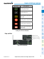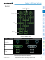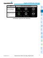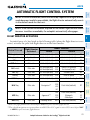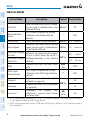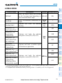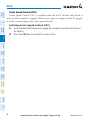
1
Embraer Prodigy™ Flight Deck 100
Cockpit Reference Guide
Embraer Phenom 100
System Software 0743.06 or later
Flight Instruments
ENGINE & AIRFRAME SYSTEMS
Nav/Com/Transponder/Audio Panel
Automatic Flight Control System
GPS Navigation
Flight Planning
Procedures
Hazard Avoidance
Additional Features
Abnormal Operation
Annunciations & Alerts
Appendix
INDEx
Copyright © 2008 Garmin Ltd. or its subsidiaries. All rights reserved.
This manual reflects the operation of System Software version 0743.06 or later for the Embraer
Phenom 100. Some differences in operation may be observed when comparing the information in
this manual to earlier or later software versions.
Garmin International, Inc., 1200 East 151st Street, Olathe, Kansas 66062, U.S.A.
Tel: 913/397.8200
Fax: 913/397.8282
Garmin AT, Inc., 2345 Turner Road SE, Salem, OR 97302, U.S.A.
Tel: 503/391.3411
Fax 503/364.2138
Garmin (Europe) Ltd, Liberty House, Bulls Copse Road, Hounsdown Business Park,
Southampton, SO40 9RB, U.K.
Tel: 44/0870.8501241
Fax: 44/0870.8501251
Garmin Corporation, No. 68, Jangshu 2nd Road, Shijr, Taipei County, Taiwan
Tel: 886/02.2642.9199
Fax: 886/02.2642.9099
Web Site Address: www.garmin.com
Except as expressly provided herein, no part of this manual may be reproduced, copied, transmitted,
disseminated, downloaded or stored in any storage medium, for any purpose without the express
written permission of Garmin. Garmin hereby grants permission to download a single copy of this
manual and of any revision to this manual onto a hard drive or other electronic storage medium to
be viewed for personal use, provided that such electronic or printed copy of this manual or revision
must contain the complete text of this copyright notice and provided further that any unauthorized
commercial distribution of this manual or any revision hereto is strictly prohibited.
Garmin® is a registered trademark of Garmin Ltd. or its subsidiaries. WATCH®, FliteCharts®, and
SafeTaxi® are trademarks of Garmin Ltd. or its subsidiaries. These trademarks may not be used
without the express permission of Garmin.
NavData® is a registered trademark of Jeppesen, Inc.; and XM® is a registered trademark of
XM Satellite Radio, Inc.; Honeywell® and Bendix/King® are registered trademarks of Honeywell
International, Inc.; CO Guardian is a trademark of CO Guardian, Inc.
July, 2008
190-00685-00 Rev. A
Printed in the U.S.A.
Warnings, Cautions & Notes
WARNING: Navigation and terrain separation must NOT be predicated upon
the use of the terrain avoidance feature. The terrain avoidance feature is NOT
intended to be used as a primary reference for terrain avoidance and does
not relieve the pilot from the responsibility of being aware of surroundings
during flight. The terrain avoidance feature is only to be used as an aid for
terrain avoidance. Terrain data is obtained from third party sources. Garmin
is not able to independently verify the accuracy of the terrain data.
WARNING: The displayed minimum safe altitudes (MSAs) are only advisory
in nature and should not be relied upon as the sole source of obstacle and
terrain avoidance information. Always refer to current aeronautical charts
for appropriate minimum clearance altitudes.
WARNING: The altitude calculated by the GPS receivers is geometric height
above Mean Sea Level and could vary significantly from the altitude displayed
by pressure altimeters, such as the GDC 74B Air Data Computer, or other
altimeters in aircraft. GPS altitude should never be used for vertical navigation.
Always use pressure altitude displayed by the PFD or other pressure altimeters
in aircraft.
WARNING: Do not use outdated database information. Databases used in
the system must be updated regularly in order to ensure that the information
remains current. Pilots using any outdated database do so entirely at their
own risk.
WARNING: Do not use basemap (land and water data) information for
primary navigation. Basemap data is intended only to supplement other
approved navigation data sources and should be considered as an aid to
enhance situational awareness.
WARNING: Traffic information shown on the multi-function display is provided
as an aid in visually acquiring traffic. Pilots must maneuver the aircraft based
only upon ATC guidance or positive visual acquisition of conflicting traffic.
WARNING: XM Weather should not be used for hazardous weather
penetration. Weather information provided by the GDL 69A is approved only
for weather avoidance, not penetration.
Cockpit Reference Guide for the Prodigy™ Flight Deck 100
190-00685-00 Rev. A
Warnings, Cautions & Notes
Warning: NEXRAD weather data is to be used for long-range planning
purposes only. Due to inherent delays in data transmission and the relative
age of the data, NEXRAD weather data should not be used for short-range
weather avoidance.
WARNING: The Prodigy™ Integrated Flight Deck, as installed in the Embraer
Phenom 100 aircraft, has a very high degree of functional integrity. However,
the pilot must recognize that providing monitoring and/or self-test capability
for all conceivable system failures is not practical. Although unlikely, it may
be possible for erroneous operation to occur without a fault indication
shown by the system. It is thus the responsibility of the pilot to detect such
an occurrence by means of cross-checking with all redundant or correlated
information available in the cockpit.
WARNING: For safety reasons, system operational procedures must be learned
on the ground.
WARNING: The United States government operates the Global Positioning
System and is solely responsible for its accuracy and maintenance. The
GPS system is subject to changes which could affect the accuracy and
performance of all GPS equipment. Portions of the system utilize GPS as a
precision electronic NAVigation AID (NAVAID). Therefore, as with all NAVAIDs,
information presented by the system can be misused or misinterpreted and,
therefore, become unsafe.
WARNING: To reduce the risk of unsafe operation, carefully review and
understand all aspects of the Prodigy™ Pilot’s Guide documentation and
the Embraer Phenom 100 Airplane Flight Manual. Thoroughly practice basic
operation prior to actual use. During flight operations, carefully compare
indications from the system to all available navigation sources, including
the information from other NAVAIDs, visual sightings, charts, etc. For safety
purposes, always resolve any discrepancies before continuing navigation.
WARNING: The illustrations in this guide are only examples. Never use
the system to attempt to penetrate a thunderstorm. Both the FAA Advisory
Circular, Subject: Thunderstorms, and the Aeronautical Information Manual
(AIM) recommend avoiding “by at least 20 miles any thunderstorm identified
as severe or giving an intense radar echo.”
190-00685-00 Rev. A
Cockpit Reference Guide for the Prodigy™ Flight Deck 100
Warnings, Cautions & Notes
WARNING: Lamp(s) inside this product may contain mercury (HG) and must
be recycled or disposed of according to local, state, or federal laws. For
more information, refer to our website at www.garmin.com/aboutGarmin/
environment/disposal.jsp.
WARNING: Because of anomalies in the earth’s magnetic field, operating
the system within the following areas could result in loss of reliable attitude
and heading indications. North of 70° North latitude and south of 70° South
latitude. An area north of 65° North latitude between longitude 75º West
and 120º West. An area south of 55° South latitude between longitude 120º
East and 165º East.
CAUTION: The PFD and MFD displays use a lens coated with a special
anti-reflective coating that is very sensitive to skin oils, waxes, and abrasive
cleaners. CLEANERS CONTAINING AMMONIA WILL HARM THE ANTIREFLECTIVE COATING. It is very important to clean the lens using a clean,
lint-free cloth and an eyeglass lens cleaner that is specified as safe for antireflective coatings.
CAUTION: The system does not contain any user-serviceable parts. Repairs
should only be made by an authorized Garmin service center. Unauthorized
repairs or modifications could void both the warranty and the pilot’s authority
to operate this device under FAA/FCC regulations.
nOTE: All visual depictions contained within this document, including screen
images of the panel and displays, are subject to change and may not reflect
the most current system and aviation databases. Depictions of equipment
may differ slightly from the actual equipment.
NOTE: This device complies with part 15 of the FCC Rules. Operation is
subject to the following two conditions: (1) this device may not cause harmful
interference, and (2) this device must accept any interference received,
including interference that may cause undesired operation.
NOTE: The data contained in the terrain and obstacle databases comes from
government agencies. Garmin accurately processes and cross-validates the
data, but cannot guarantee the accuracy and completeness of the data.
Cockpit Reference Guide for the Prodigy™ Flight Deck 100
190-00685-00 Rev. A
Warnings, Cautions & Notes
NOTE: This product, its packaging, and its components contain chemicals
known to the State of California to cause cancer, birth defects, or reproductive
harm. This notice is being provided in accordance with California’s Proposition
65. If you have any questions or would like additional information, please
refer to our web site at www.garmin.com/prop65.
NOTE: Interference from GPS repeaters operating inside nearby hangars can
cause an intermittent loss of attitude and heading displays while the aircraft
is on the ground. Moving the aircraft more than 100 yards away from the
source of the interference should alleviate the condition.
NOTE: Use of polarized eyewear may cause the flight displays to appear dim
or blank.
NOTE: The purpose of this Cockpit Reference Guide is to provide the pilot
a resource with which to find operating instructions on the major features
of the Prodigy system more easily. It is not intended to be a comprehensive
operating guide. Complete operating procedures for the complete system
are found in the Prodigy Flight Deck 100 Pilot’s Guide.
190-00685-00 Rev. A
Cockpit Reference Guide for the Prodigy™ Flight Deck 100
Warnings, Cautions & Notes
Blank Page
Cockpit Reference Guide for the Prodigy™ Flight Deck 100
190-00685-00 Rev. A
Record of Revisions
Part Number
190-00685-00
Change Summary
Initial release
Revision Date of Revision
A
July, 2008
190-00685-00 Rev. A
Affected Pages
Description
Production release
Cockpit Reference Guide for the Prodigy™ Flight Deck 100
RR-1
Record of Revisions
Blank Page
RR-2
Cockpit Reference Guide for the Prodigy™ Flight Deck 100
190-00685-00 Rev. A
Table of Contents
Flight Instruments. ............................................................................................................... 1
Selecting the Altimeter Barometric Pressure Setting....................................................... 1
Selecting Standard Barometric Pressure.............................................................................. 1
Change Altimeter Barometric Pressure Setting Units....................................................... 1
Synchronizing the Altimeter Barometric Pressure Settings............................................ 1
Synchronize CDI......................................................................................................................... 1
Change Navigation Sources.................................................................................................... 2
Enable/Disable OBS Mode While Navigating with GPS..................................................... 2
Generic Timer.............................................................................................................................. 2
Configure Vspeed Bugs Individually...................................................................................... 2
Turn Vspeed Bugs On or Off by Category............................................................................. 3
Set Barometric Minimum Descent Altitude......................................................................... 3
Displaying Wind Data............................................................................................................... 3
Engine & Airframe Systems............................................................................................. 5
Engine Indication System........................................................................................................ 5
Synoptics................................................................................................................................... 10
Nav/Com/Transponder/Audio Panel....................................................................... 19
Enter or Change Flight ID...................................................................................................... 19
DME Tuning............................................................................................................................... 19
Enter a Transponder Code..................................................................................................... 19
Selecting a COM Radio........................................................................................................... 20
Selecting a NAV Radio............................................................................................................ 20
NAV/COM Tuning...................................................................................................................... 20
Intercom..................................................................................................................................... 20
Passenger Address (PA) System............................................................................................ 21
Clearance Recorder and Player............................................................................................ 21
Automatic Flight Control System........................................................................... 23
Flight Director Activation...................................................................................................... 23
Vertical Modes.......................................................................................................................... 24
Lateral Modes........................................................................................................................... 25
GPS Navigation......................................................................................................................... 27
Direct-to Navigation............................................................................................................... 27
Activate a Stored Flight Plan................................................................................................ 28
Activate a Flight Plan Leg...................................................................................................... 28
Stop Navigating a Flight Plan............................................................................................... 29
Vertical Navigation (VNAV)................................................................................................... 29
190-00685-00 Rev. A
Cockpit Reference Guide for the Prodigy™ Flight Deck 100
i
Table of Contents
Flight Planning....................................................................................................................... 31
Weight Planning....................................................................................................................... 31
Trip Planning............................................................................................................................. 31
Create a New User Waypoint................................................................................................ 33
Delete a User Waypoint.......................................................................................................... 34
Create a New Flight Plan....................................................................................................... 34
Insert a Waypoint in the Active Flight Plan....................................................................... 36
Enter an Airway in a Flight Plan........................................................................................... 36
Invert An Active Flight Plan................................................................................................... 37
Remove a Departure, Arrival, Approach, or Airway from a Flight Plan...................... 37
Store a Flight Plan................................................................................................................... 38
Edit a Stored Flight Plan........................................................................................................ 38
Delete a Waypoint from the Flight Plan............................................................................. 38
Invert and Activate a Stored Flight Plan............................................................................ 39
Copy a Flight Plan.................................................................................................................... 39
Delete a Flight Plan................................................................................................................. 39
Graphical Flight Plan Creation.............................................................................................. 40
Procedures................................................................................................................................. 41
Load and Activate a Departure Procedure........................................................................ 41
Activate A Departure Leg...................................................................................................... 41
Load An Arrival Procedure..................................................................................................... 41
Activate An Arrival Leg.......................................................................................................... 42
Load and/or Activate an Approach Procedure.................................................................. 42
Activate An Approach in the Active Flight Plan................................................................ 43
Activate a Vector to Final Approach Fix............................................................................. 43
Activate A Missed Approach in the Active Flight Plan.................................................... 44
Hazard Avoidance................................................................................................................. 45
Customizing the Hazard Displays on the Navigation Map............................................. 45
XM Weather (Optional)........................................................................................................... 45
Traffic Information Service (TIS).......................................................................................... 47
Terrain Awareness & Warning System (TAWS) Display.................................................... 48
Airborne Color Weather Radar............................................................................................. 50
Additional Features............................................................................................................ 53
SafeTaxi®................................................................................................................................... 53
XM® Radio Entertainment..................................................................................................... 53
ii
Cockpit Reference Guide for the Prodigy™ Flight Deck 100
190-00685-00 Rev. A
Table of Contents
Abnormal Operation.......................................................................................................... 57
Engine......................................................................................................................................... 57
Cabin pressurization............................................................................................................... 57
Flaps............................................................................................................................................ 58
Trim............................................................................................................................................. 58
Reversionary Mode................................................................................................................. 58
Abnormal COM Operation..................................................................................................... 59
Hazard Displays with Loss of GPS Position........................................................................ 59
Unusual Attitudes.................................................................................................................... 60
Dead Reckoning....................................................................................................................... 60
Annunciations & Alerts................................................................................................... 63
CAS Messages........................................................................................................................... 63
Aural Alerts............................................................................................................................... 68
Other Prodigy™ Aural Alerts.................................................................................................. 68
Comparator Annunciations.................................................................................................... 69
Reversionary Sensor Annunciations.................................................................................... 69
TAWS Alerts............................................................................................................................... 70
MFD & PFD Message Advisories........................................................................................... 72
Database Message Advisories.............................................................................................. 73
GMA 1347D Message Advisories.......................................................................................... 76
GIA 63W Message Advisories................................................................................................ 77
GSD 41 Message Advisories.................................................................................................. 80
GEA 71 Message Advisories................................................................................................... 80
GTX 33/33D Message Advisories........................................................................................... 81
GRS 77 Message Advisories................................................................................................... 81
GMU 44 Message Advisories................................................................................................. 83
GDL 69A Message Advisories................................................................................................ 83
GWX 68 Alert Messages.......................................................................................................... 84
GDC 74B Message Advisories................................................................................................ 84
GCU 475 Message Advisories................................................................................................ 85
GMC 715 Message Advisories............................................................................................... 85
Miscellaneous Message Advisories...................................................................................... 86
Appendix........................................................................................................................................ 91
PFD Softkey Map..................................................................................................................... 91
MFD Softkey Map.................................................................................................................... 96
Index..........................................................................................................................................Index-1
190-00685-00 Rev. A
Cockpit Reference Guide for the Prodigy™ Flight Deck 100
iii
Table of Contents
Blank Page
iv
Cockpit Reference Guide for the Prodigy™ Flight Deck 100
190-00685-00 Rev. A
Flight Instruments
Flight
Instruments
Flight Instruments
Selecting the Altimeter Barometric Pressure Setting
EAS
Turn the BARO Knob to select the desired setting.
Nav/Com/
XPDR/Audio
Selecting Standard Barometric Pressure
Press the BARO Knob.
AFCS
Change Altimeter Barometric Pressure Setting Units
1) Select the PFD Softkey to display the second-level softkeys.
Or:
Select the HPA Softkey to display the barometric pressure setting in
hectopascals.
Procedures
Flight
Planning
3) Select the IN Softkey to display the barometric pressure setting in inches of
mercury (in Hg).
GPS Nav
2) Select the ALT UNIT Softkey.
4) Select the BACK Softkey to return to the top-level softkeys.
Hazard
Avoidance
Synchronizing the Altimeter Barometric Pressure Settings
Additional
Features
1) Select the AUX-SYSTEM SETUP Page on the MFD.
2) Press the FMS Knob to activate the cursor.
Abnormal
Operation
3) Turn the large FMS Knob to highlight BARO in the SYNCHRONIZATION
Window.
4) Turn the small FMS Knob clockwise to ON or counterclockwise to OFF.
Annun/
Alerts
Synchronize CDI
1) Select the AUX-SYSTEM SETUP Page on the MFD.
Appendix
2) Press the FMS Knob to activate the cursor.
3) Turn the large FMS Knob to highlight CDI in SYNCHRONIZATION Window.
190-00685-00 Rev. A
Cockpit Reference Guide for the Prodigy™ Flight Deck 100
Index
4) Turn the small FMS Knob clockwise to ON or counterclockwise to OFF.
1
Change Navigation Sources
1) Select the CDI Softkey to change from GPS to VOR1 or LOC1. This places
the light blue tuning box over the NAV1 standby frequency in the upper left
corner of the PFD.
EAS
Flight
Instruments
Flight Instruments
3) Select the CDI Softkey a third time to return to GPS.
Enable/Disable OBS Mode While Navigating with GPS
1) Select the OBS Softkey to select OBS Mode.
GPS Nav
AFCS
Nav/Com/
XPDR/Audio
2) Select the CDI Softkey again to change from VOR1 or LOC1 to VOR2
or LOC2. This places the light blue tuning box over the NAV2 standby
frequency.
3) Select the OBS Softkey again to disable OBS Mode.
Generic Timer
1) Select the TMR/REF Softkey, then turn the large FMS Knob to select the
time field (hh/mm/ss). Turn the FMS Knobs to set the desired time, then
press the ENT Key. The UP/DOWN field is now highlighted.
Hazard
Avoidance
Procedures
Flight
Planning
2) Turn the CRS Knob to select the desired course to/from the waypoint. Press
the CRS Knob to slew the CDI Course Pointer to a course bearing directly
to the waypoint.
Additional
Features
2) Turn the small FMS Knob to display the UP/DOWN window. Turn the FMS
Knob to select ‘UP’ or ‘DOWN’, then press the ENT Key. ‘START?’ is now
highlighted.
Configure Vspeed Bugs Individually
1) Select the TMR/REF Softkey.
2) Turn the large FMS Knob to highlight the desired Vspeed.
3) Use the small FMS Knob to change the Vspeed in 1-kt increments (when a
Appendix
Annun/
Alerts
Abnormal
Operation
3) Press the ENT Key to START, STOP, or RESET the timer (if the timer is
counting DOWN, it will start counting UP after reaching zero). Press the
CLR Key or the TMR/REF Softkey to remove the window.
Index
speed has been changed from a default value, an asterisk appears next to
the speed).
2
Cockpit Reference Guide for the Prodigy™ Flight Deck 100
190-00685-00 Rev. A
Flight Instruments
Flight
Instruments
4) Press the ENT Key or turn the large FMS Knob to highlight the ON/OFF
field.
5) Turn the small FMS Knob clockwise to ON or counterclockwise to OFF.
EAS
6) To remove the window, press the CLR Key or the TMR/REF Softkey.
Turn Vspeed Bugs On or Off by Category
Nav/Com/
XPDR/Audio
1) Press the TMR/REF Softkey.
2) Press the MENU Key.
AFCS
3) Turn the FMS Knob to highlight the desired option.
4) Press the ENT Key. Press the TMR/REF Softkey to remove the window.
GPS Nav
Set Barometric Minimum Descent Altitude
Flight
Planning
1) Press the TMR/REF Softkey.
2) Turn the large FMS Knob to highlight the OFF/BARO field to the right of
‘Minimums’.
Procedures
3) Turn the small FMS Knob clockwise to BARO.
4) Press the ENT Key.
Hazard
Avoidance
5) Use the small FMS Knob to enter the desired altitude.
6) Press the ENT Key.
Additional
Features
7) To remove the window, press the CLR Key or the TMR/REF Softkey.
Displaying Wind Data
2) Select the WIND Softkey to display wind data below the Selected Heading.
Annun/
Alerts
3) Select one of the OPTN softkeys to change how wind data is displayed.
Abnormal
Operation
1) Select the PFD Softkey.
4) To remove the Wind Data Window, select the OFF Softkey.
Appendix
Index
190-00685-00 Rev. A
Cockpit Reference Guide for the Prodigy™ Flight Deck 100
3
Index
Appendix
Annun/
Alerts
Abnormal
Operation
Additional
Features
Hazard
Avoidance
Procedures
Flight
Planning
GPS Nav
AFCS
Nav/Com/
XPDR/Audio
EAS
Flight
Instruments
Flight Instruments
Blank Page
4
Cockpit Reference Guide for the Prodigy™ Flight Deck 100
190-00685-00 Rev. A
Engine & Airframe Systems
Flight
Instruments
Engine & Airframe Systems
Engine Indication System
12
EAS
1
2
2
Nav/Com/
XPDR/Audio
1
AFCS
3
GPS Nav
3
4
4
Flight
Planning
5
5
6
7
Procedures
6
7
Hazard
Avoidance
8
9
10
8
Additional
Features
9
10
Abnormal
Operation
11
11
EIS Display (Reversionary Mode)
7
Pressurization Display
2
Interstage Turbine Temperature (ITT)
8
Speed Brake Status
3
9
Landing Gear Status
4
Engine High Pressure Compressor
Rotation Speed
Oil Pressure and Temperature
10
Flap Indicator
5
Fuel Display
11
Trim Indicator
6
Battery Voltmeter
12
Thrust Rating Indication(top)/Automatic
Thrust Reserve status (bottom)
190-00685-00 Rev. A
Cockpit Reference Guide for the Prodigy™ Flight Deck 100
Index
Engine Fan Rotation Speed
Appendix
1
Annun/
Alerts
EICAS Display (Normal Mode)
5
Engine & Airframe Systems
Flight
Instruments
Thrust Rating
AFCS
Nav/Com/
XPDR/Audio
EAS
Indication
CRZ
CLB
CON
TO
GA
Thrust Rating
Cruise
Climb
Continuous
Takeoff
Go Around
GPS Nav
Thrust Rating Indications
Hazard
Avoidance
Procedures
Flight
Planning
Selecting a thrust rating:
1) Select the SYSTEM Softkey.
2) Select the ENG SET Softkey
3) To choose the continuous thrust rating, select the CON Softkey,
Or:
To choose the maximum climb thrust rating, select the CLB Softkey.
4) Select the BACK Softkey to return to the previous softkey level.
Additional
Features
Automatic Thrust Reserve
Abnormal
Operation
Indication*
ATR
ATR
TO - RSV
Description
ATR enabled in both engines
ATR armed in both engines, but inactive
ATR activated in at least one engine
Annun/
Alerts
* When no indication is shown, ATR has not been enabled or armed
in both engines.
Appendix
Automatic Thrust Reserve (ATR) Status
Index
Disabling/enabling Automatic Thrust Reserve (ATR):
1) Select the SYSTEM Softkey.
2) Select the ENG SET Softkey to display the Takeoff Data Set Window.
6
Cockpit Reference Guide for the Prodigy™ Flight Deck 100
190-00685-00 Rev. A
Engine & Airframe Systems
Flight
Instruments
3) To disable ATR, select the ATR OFF Softkey;
Or:
To enable ATR, select the ATR ON Softkey.
EAS
4) If desired, change the OAT while the Takeoff Data Set Window is displayed.
Nav/Com/
XPDR/Audio
5) To confirm the selected takeoff settings and close the Takeoff Data Set
Window, select the ACCEPT Softkey,
Or:
To cancel the operation, select the BACK Softkey.
AFCS
Fuel and Electrical Indications
GPS Nav
Engine Fuel Flow
Flight
Planning
Tank Fuel Quantity
Total Fuel Quantity
Fuel Temperature
Procedures
Fuel Display
Hazard
Avoidance
Additional
Features
Electrical Display
Abnormal
Operation
Cabin Pressurization
Annun/
Alerts
High Landing Field Elevation
Pressure Altitude
Pressure Change Rate
Appendix
Pressure Differential
Landing Field Elevation
Oxygen System Pressure
Index
Cabin Pressure Display
190-00685-00 Rev. A
Cockpit Reference Guide for the Prodigy™ Flight Deck 100
7
Engine & Airframe Systems
Flight
Instruments
Setting the displayed landing field elevation:
1) Select the SYSTEM Softkey.
2) Select the LFE Softkey.
EAS
3) Select the FMS LFE Softkey to set the LFE to the value for the destination
airport in the current flight plan.
Nav/Com/
XPDR/Audio
Or:
Use the ±500 and ±50 FT softkeys to set the desired elevation.
AFCS
4) To confirm the new LFE value, select the ACCEPT Softkey.
GPS Nav
Speed Brakes and Landing Gear
Flight
Planning
Speed Brake Status
Procedures
Main Landing Gear
Hazard
Avoidance
Left-side Landing
Gear
Right-side Landing
Gear
Additional
Features
Speed Brake and Landing Gear
Indications
Annun/
Alerts
Abnormal
Operation
Indication
CLOSED
OPEN
NOT AVAIL
Description
Speed brakes retracted
Speed brakes deployed
Invalid information
Index
Appendix
Speed Brake Indications
8
Cockpit Reference Guide for the Prodigy™ Flight Deck 100
190-00685-00 Rev. A
Engine & Airframe Systems
Description
Flight
Instruments
Indication
Landing Gear Down
EAS
Landing Gear Up
Nav/Com/
XPDR/Audio
Landing Gear Transitioning
(Normal)
AFCS
Landing Gear Locked Down
GPS Nav
Landing Gear Locked Up
Flight
Planning
Landing Gear Transitioning
(Abnormal)
Procedures
Landing Gear Position Indications
Hazard
Avoidance
Flaps and Trim
Flap Position
Additional
Features
Flap Selected Bug
Flap Lever Setting
Abnormal
Operation
Annun/
Alerts
Flap and Trim Indications
Appendix
Index
190-00685-00 Rev. A
Cockpit Reference Guide for the Prodigy™ Flight Deck 100
9
Synoptics
1
2
3
4
5
6
7
Nav/Com/
XPDR/Audio
EAS
Flight
Instruments
Engine & Airframe Systems
10
GPS Nav
AFCS
8
Annun/
Alerts
Abnormal
Operation
Additional
Features
Hazard
Avoidance
Procedures
Flight
Planning
9
1
System Clock
6
Hrdraulic Pressure
2
Static Air Temperature (SAT)
7
Oxygen
3
Total Air Temperature (TAT)
8
Emergency Brake Accumulator Pressure
4
True Airspeed (TAS)
9
Door Status
5
Aircraft Gross Weight
10
Electrical
Index
Appendix
System Status Synoptics Page
10
Cockpit Reference Guide for the Prodigy™ Flight Deck 100
190-00685-00 Rev. A
Engine & Airframe Systems
Flight
Instruments
Environmental Control System (ECS)
EAS
3
1
4
5
Nav/Com/
XPDR/Audio
2
6
7
8
AFCS
9
11
10
GPS Nav
12
17
18
19
20
Hazard
Avoidance
16
Procedures
14
15
Flight
Planning
13
Cockpit Temperature Setting
11
Outflow Valve (OFV) Status*
2
Actual Cockpit Temperature
12
Heat Exchanger Pack Cooling Circuit
3
Cockpit Evaporator Fan
13
Bleed Line 1 (Left) Pressure
4
Cabin Temperature Setting
14
Bleed Line 2 (Right) Pressure
5
Actual Cabin Temperature
15
Cockpit Duct Temperature Setting
6
Cabin Evaporator Fan
16
Cabin Duct Temperature Setting
7
Flow Control Shutoff Valve (FCV) 1
17
Pressure Regulating Shutoff Valve (PRSOV) 1
8
Flow Control Shutoff Valve (FCV) 2
18
Pressure Regulating Shutoff Valve (PRSOV) 2
9
Ram Air Valve (RAV)
19
Ground Cooling Fan (GCF)
10
Ram Air Duct
20
Vapor Cycle System (VCS)
Additional
Features
1
Abnormal
Operation
Appendix
Index
Environmental Control System Synoptics Page
190-00685-00 Rev. A
Cockpit Reference Guide for the Prodigy™ Flight Deck 100
Annun/
Alerts
* Outflow valve (OFV) status is displayed only while the aircraft is parked or taxiing.
11
Unit
Icons and Descriptions
Fan
Procedures
Off
On
Off
On
Off
Vapor Cycle System
PRSOV
Open with flow
Open, no flow
Closed
Ram Air Duct From
NACA Scoop
Airborne
On ground
Ram Air Valve
Closed
Additional
Features
Hazard
Avoidance
On
Heat Exchanger
Flight
Planning
GPS Nav
AFCS
Nav/Com/
XPDR/Audio
EAS
Flight
Instruments
Engine & Airframe Systems
Open, airborne
Open, on ground
Index
Appendix
Annun/
Alerts
Abnormal
Operation
Environmental Control System Unit Status Indications
12
Cockpit Reference Guide for the Prodigy™ Flight Deck 100
190-00685-00 Rev. A
Engine & Airframe Systems
Flight
Instruments
Electrical
Ground Power Unit
EAS
Nav/Com/
XPDR/Audio
Generator
AFCS
GPS Nav
Bus
Flight
Planning
Procedures
Battery
Hazard
Avoidance
Electrical Synoptics Page
Additional
Features
Unit
Icons and Descriptions
Abnormal
Operation
Generator
On
Off
Annun/
Alerts
Bus
Off Bus
Abnormal
Normal
Abnormal
Appendix
Normal
Battery
Index
Electrical System Unit Status Indications
190-00685-00 Rev. A
Cockpit Reference Guide for the Prodigy™ Flight Deck 100
13
Engine & Airframe Systems
Flight
Instruments
Fuel
2
3
4
5
6
7
8
9
10
11
12
13
Procedures
Flight
Planning
GPS Nav
AFCS
Nav/Com/
XPDR/Audio
EAS
1
Appendix
Annun/
Alerts
Abnormal
Operation
Additional
Features
Hazard
Avoidance
14
15
1
Fuel Transfer SOV
9
Fuel 2 SOV
2
Left Tank Fuel Quantity
10
Total Fuel
3
Right Tank Fuel Quantity
11
Fuel Used
4
Left DC Pump
12
LH Pressure Switch
5
Right DC Pump
13
RH Pressure Switch
6
Left Feed Ejector
14
Left Engine Feed Line
7
Right Feed Ejector
15
Right Engine Feed Line
8
Fuel 1 SOV
Index
Fuel Synoptics Page
14
Cockpit Reference Guide for the Prodigy™ Flight Deck 100
190-00685-00 Rev. A
Engine & Airframe Systems
Icons and Descriptions
Flight
Instruments
Unit
Fuel Line
Not operating
Operating
Not operating
Operating
Not operation
EAS
Operating
AFCS
Fuel Pressure
Switch
Nav/Com/
XPDR/Audio
Feed Ejector
GPS Nav
Valve
Open with flow Open, no flow
In transit
Closed
Flight
Planning
DC Pump
Operating
Procedures
Not operating
Fuel Transfer Valve
In transit
Closed
Hazard
Avoidance
Open with flow
Fuel System Unit Status Indications
Additional
Features
Abnormal
Operation
Annun/
Alerts
Appendix
Index
190-00685-00 Rev. A
Cockpit Reference Guide for the Prodigy™ Flight Deck 100
15
Engine & Airframe Systems
Flight
Instruments
Ice Protection System
2
2
3
4
5
6
7
8
9
10
11
12
Blank Page
Abnormal
Operation
Additional
Features
Hazard
Avoidance
Procedures
Flight
Planning
GPS Nav
AFCS
Nav/Com/
XPDR/Audio
EAS
1
2
1
Windshield Heaters
7
EAI 1 Valve and Bleed Line
2
Boot Lines and Valves
8
EAI 2 Valve and Bleed Line
3
Inboard Ejector Flow Control Valve
9
4
Outboard Ejector Flow Control Valve
5
Engine Anti-ice 1 Bleed Duct and Lip Skin
Pressure Regulating Shut-Off Valve 1
(PRSOV 1)
10 Pressure Regulating Shut-Off Valve 2
(PRSOV 2)
11 Ice Protection Bleed Duct
6
Engine Anti-ice 2 Bleed Duct and Lip Skin
12
STAB EFCV
Index
Appendix
Annun/
Alerts
Ice Protection Synoptics Page
16
Cockpit Reference Guide for the Prodigy™ Flight Deck 100
190-00685-00 Rev. A
Engine & Airframe Systems
Icons and Descriptions
Closed
Open with flow Open, no flow
Closed
Nav/Com/
XPDR/Audio
STB EFCV and, EAI
Valve
Open with flow Open, no flow
EAS
Inboard/Outboard
EFCV and PRSOV
Flight
Instruments
Unit
AFCS
Ice Protection System Unit Status Indications
GPS Nav
Flight
Planning
Procedures
Hazard
Avoidance
Additional
Features
Abnormal
Operation
Annun/
Alerts
Appendix
Index
190-00685-00 Rev. A
Cockpit Reference Guide for the Prodigy™ Flight Deck 100
17
Index
Appendix
Annun/
Alerts
Abnormal
Operation
Additional
Features
Hazard
Avoidance
Procedures
Flight
Planning
GPS Nav
AFCS
Nav/Com/
XPDR/Audio
EAS
Flight
Instruments
Engine & Airframe Systems
Blank Page
18
Cockpit Reference Guide for the Prodigy™ Flight Deck 100
190-00685-00 Rev. A
Nav/Com/XPDR/Audio Panel
Flight
Instruments
Nav/Com/Transponder/Audio Panel
Enter or Change Flight ID
3) Turn the large FMS Knob to select the next field.
AFCS
4) Turn the small FMS Knob to enter the next desired character.
Nav/Com/
XPDR/Audio
2) Turn the small FMS Knob to enter the first character.
EAS
1) Press the TMR/REF Softkey, then turn the large FMS Knob to highlight the
Flight ID field.
5) Repeat steps 3 and 4 until the desired Flight ID is entered.
GPS Nav
6) Press the ENT Key to update the Flight ID.
DME Tuning
Flight
Planning
1) Press the DME Softkey.
Procedures
2) If two DMEs are installed, turn the large FMS to select the DME source
field.
3) Turn the small FMS Knob to select the desired Nav radio.
Hazard
Avoidance
4) Press the ENT Key to complete the selection.
Enter a Transponder Code
3) Press the CODE Softkey to display the transponder code selection softkeys,
for digit entry.
Annun/
Alerts
Appendix
4) Press the digit softkeys to enter the code in the code field. When entering
the code, the next key in sequence must be pressed within 10 seconds, or
the entry is cancelled and restored to the previous code. Five seconds after
the fourth digit has been entered, the transponder code becomes active.
Abnormal
Operation
2) If the aircraft is equipped with two transponders, press the XPDR1 or
XPDR2 Softkey to select the active transponder.
Additional
Features
1) Press the XPDR Softkey to display the transponder mode selection softkeys.
Index
190-00685-00 Rev. A
Cockpit Reference Guide for the Prodigy™ Flight Deck 100
19
Selecting a COM Radio
Transmit/Receive
EAS
Flight
Instruments
Nav/Com/XPDR/Audio Panel
Receive Only
Nav/Com/
XPDR/Audio
AFCS
Press the COM1 MIC, COM2 MIC, or COM3 MIC Key (HF, if installed) on
the audio panel.
Press the COM1, COM2, or COM3 Key (HF, if installed) on the audio panel.
Selecting a NAV Radio
2) Pressing the NAV1, NAV2, DME, or ADF Key on the audio panel selects
and deselects the navigation radio audio source. All radio keys can be
selected individually or together.
NAV/COM Tuning
Procedures
Flight
Planning
GPS Nav
1) Press the CDI Softkey to select NAV1 (VOR1/LOC1) or NAV2 (VOR2/LOC2).
Hazard
Avoidance
3) Press the Frequency Transfer Key to place the frequency into the active
frequency field.
Index
Appendix
Annun/
Alerts
Abnormal
Operation
2) Turn the respective tuning knobs to enter the desired frequency into the
standby frequency field. The large knob enters MHz and the small knob
enters kHz.
Additional
Features
1) Press the small tuning knob to select the desired radio for tuning. A light
blue box highlights the radio frequency to be tuned.
Intercom
Pressing the INTR COM Key on either Audio Panel selects and deselects the
intercom on both Audio Panels. The annunciator is lit when the intercom is active.
The intercom connects the pilot and copilot together. Either the pilot or copilot may
select or deselect the intercom.
The CABIN Key initiates two way communication between the pilot or copilot and
the passengers in the cabin. The annunciator is lit when the cabin intercom is active
on either Audio Panel.
The MAN SQ Key allows either automatic or manual control of the intercom
squelch setting. Pressing the MAN SQ Key enables manual squelch control, indicated
by the MAN SQ annunciator.
20
Cockpit Reference Guide for the Prodigy™ Flight Deck 100
190-00685-00 Rev. A
Nav/Com/XPDR/Audio Panel
Flight
Instruments
During manual squelch operation, pressing the ICS Knob switches between volume
and squelch adjustment, lighting the associated annunciator beneath the knob. When
the MAN SQ annunciator is lit, the ICS Knob controls both volume and squelch. When
the MAN SQ annunciator is extinguished, the ICS Knob controls only volume.
EAS
Passenger Address (PA) System
Nav/Com/
XPDR/Audio
AFCS
A passenger address system is provided by pressing the PA Key to deliver messages
to the passengers. The message is heard by the other pilot on the headset only if the
PA Key is enabled on both audio panels. PA messages are one way from the flight deck
to the passengers.
Clearance Recorder and Player
Abnormal
Operation
Annun/
Alerts
Appendix
Pressing the PLAY Key twice within one-half second while audio is playing
plays the previous block of recorded audio. Each subsequent two presses
of the PLAY Key within one-half second backtracks through the recorded
memory blocks to reach and play any recorded block.
Additional
Features
Pressing the PLAY Key once plays the latest recorded memory block and
then returns to normal operation. Pressing the PLAY Key again during play
of a memory block stops play. If a COM input signal is detected during play
of a recorded memory block, play is halted.
Hazard
Avoidance
The PLAY Key controls the play function. The PLAY annunciator is
illuminated to indicate when play is in progress. The PLAY annunciator
extinguishes after playback is finished.
Procedures
Recorded COM audio is stored in separate memory blocks. Once 2.5
minutes of recording time have been reached, the recorder begins recording
over the stored memory blocks, starting from the oldest block.
Flight
Planning
NOTE: Pressing the play key on the pilot’s Audio Panel plays recorded audio
to the Pilot. Pressing the play key on the Copilot’s Audio Panel plays recorded
audio to the Copilot.
GPS Nav
Index
190-00685-00 Rev. A
Cockpit Reference Guide for the Prodigy™ Flight Deck 100
21
Index
Appendix
Annun/
Alerts
Abnormal
Operation
Additional
Features
Hazard
Avoidance
Procedures
Flight
Planning
GPS Nav
AFCS
Nav/Com/
XPDR/Audio
EAS
Flight
Instruments
Nav/Com/XPDR/Audio Panel
Blank Page
22
Cockpit Reference Guide for the Prodigy™ Flight Deck 100
190-00685-00 Rev. A
AFCS
Note: If the attitude information required for the default flight director modes
becomes invalid or unavailable, the autopilot automatically disengages.
AFCS
Flight Director Activation
Copilot-side
AP Key
Pilot-side
CWS Button
Pilot-side
GA Switch
Pilot-side
ALT Key
Pilot-side
VS Key
Pilot-side
VNV Key
Pilot-side
Pilot-side
ROL
ROL
ROL
ROL
ROL
ROL
ROL
PIT
Pitch Hold (default)
Glidepath
Glideslope
PIT
GP
GS
Pitch Hold (default)
PIT
APR Key
Pilot-side
Approach**
GPS
VOR
LOC
HDG Key
Pilot-side
Heading Select
HDG
Appendix
Pitch Hold (default)
Annun/
Alerts
Navigation**
GPS
VOR
LOC
BC
Abnormal
Operation
NAV Key
ROL
Additional
Features
FD Key (copilot-side)
ROL
Vertical
Pitch Hold (default)
PIT
Pitch Hold (default)
PIT
Pitch Hold (default)
PIT
Pitch Hold (default)
PIT
Takeoff (on ground)
TO
Go Around (in air)
GA
Altitude Hold
ALT
Vertical Speed
VS
Vertical Path Tracking* VPTH
Hazard
Avoidance
Pilot-side
Lateral
Roll Hold (default)
Roll Hold (default)
Roll Hold (default)
Roll Hold (default)
Roll Hold (default)
Roll Hold (default)
Roll Hold (default)
Roll Hold (default)
Roll Hold (default)
Procedures
FD Key (pilot-side)
Modes Selected
Flight
Planning
Flight Director
Activated
GPS Nav
An initial press of a key listed in the following table (when the flight director is not
active) activates the pilot-side flight director in the listed modes.
Control Pressed
Nav/Com/
XPDR/Audio
Note: If sensor information (other than attitude) required for a flight director
mode becomes invalid or unavailable, the flight director automatically reverts
to the default mode for that axis.
EAS
Flight
Instruments
Automatic Flight Control System
*Valid VNV flight plan must be entered before VNV Key press activates flight director.
190-00685-00 Rev. A
Cockpit Reference Guide for the Prodigy™ Flight Deck 100
23
Index
**The selected navigation receiver must have a valid VOR or LOC signal or active GPS course before NAV
or APR Key press activates flight director.
Flight
Instruments
AFCS
Vertical Modes
AFCS
Nav/Com/
XPDR/Audio
EAS
Vertical Mode
Pitch Hold
Selected Altitude
Armed
Index
Appendix
Annun/
Alerts
Abnormal
Operation
Additional
Features
Hazard
Avoidance
Procedures
Flight
Planning
GPS Nav
Altitude Hold
Vertical Speed
Description
Control Annunciation
Holds the current aircraft pitch attitude;
may be used to climb/descend to the (default)
Selected Altitude
AFCS armed to capture the altitude
displayed in the Selected Altitude
*
window
Holds the current Altitude Reference
ALT Key
Maintains the current aircraft vertical
speed; may be used to climb/descend VS Key
to the Selected Altitude
Flight Level Change, Maintains the current aircraft airspeed
IAS Hold
(in IAS or Mach) while the aircraft is
FLC Key
Flight Level Change, climbing/descending to the Selected
Altitude
Mach Hold
VNAV
VNAV Target
Altitude Armed
Glidepath
Glideslope
Go Around
Captures and tracks the VNAV flight VNV
path
Key
AFCS armed to capture the altitude
displayed in the VNAV Target Altitude
**
window
Captures and tracks the WAAS
glidepath on approach
APR Key
Captures and tracks the ILS glideslope
on approach
Disengages the autopilot and
GA
commands a constant pitch attitude
Switch
and wings level
PIT
ALTS
ALT
nnnnn ft
VS
nnnn fpm
FLC
nnn kt
FLC
M .nnn
VPTH
ALTV
GP
GS
GA
* ALTS armed automatically when PIT, VS, FLC, or GA active, and under VPTH when Selected Altitude
is to be captured instead of VNAV Target Altitude
** ALTV armed automatically under VPTH when VNAV Target Altitude is to be captured instead of
Selected Altitude
24
Cockpit Reference Guide for the Prodigy™ Flight Deck 100
190-00685-00 Rev. A
AFCS
Lateral Mode
GPS
GPS Nav
Captures and tracks the selected
navigation source (GPS, VOR, LOC)
VOR
NAV
Key
LOC
Procedures
BC
Hazard
Avoidance
Captures and tracks a localizer signal
for backcourse approaches
Flight
Planning
GPS
VAPP
Abnormal
Operation
Captures and tracks the selected
APR Key
navigation source (GPS, VOR, LOC)
Additional
Features
LOC
Annun/
Alerts
Navigation, GPS
Arm/Capture/Track
Navigation, VOR
Enroute Arm/
Capture/Track
Navigation, LOC
Arm/Capture/Track
(No Glideslope)
Navigation,
Backcourse Arm/
Capture/Track
Approach, GPS
Arm/Capture/Track**
Approach, VOR
Arm/Capture/Track
Approach, ILS Arm/
Capture/Track
(Glideslope Mode
automatically armed)
AFCS
Heading Select
Nav/Com/
XPDR/Audio
Low Bank
EAS
Roll Hold
Description
Control Annunciation
Holds the current aircraft roll attitude
or rolls the wings level, depending on (default)
ROL
the commanded bank angle
Limits the maximum commanded roll BANK
*
angle
Key
Captures and tracks the Selected HDG
HDG
Heading
Key
Flight
Instruments
Lateral Modes
Appendix
* No annunciation appears in the AFCS Status Box. The acceptable bank angle range is indicated in
green along the Roll Scale of the Attitude Indicator.
** Glidepath Mode automatically arms if vertical guidance is available for the selected approach.
Index
190-00685-00 Rev. A
Cockpit Reference Guide for the Prodigy™ Flight Deck 100
25
Cruise Speed Control (CSC)
Cruise Speed Control (CSC) is available while the AFCS Altitude Hold Mode is
active and the autopilot is engaged. When active, green arcs appear on the N1 gauges,
at values corresponding to the cruise speed selected.
Selecting Cruise Speed Control (CSC):
1) Enter Altitude Hold Mode and engage the autopilot (see the AFCS Section
for details).
2) Press the CSC Key (on the AFCS Control Unit).
Index
Appendix
Annun/
Alerts
Abnormal
Operation
Additional
Features
Hazard
Avoidance
Procedures
Flight
Planning
GPS Nav
AFCS
Nav/Com/
XPDR/Audio
EAS
Flight
Instruments
AFCS
26
Cockpit Reference Guide for the Prodigy™ Flight Deck 100
190-00685-00 Rev. A
GPS Navigation
Flight
Instruments
GPS Navigation
Direct-to Navigation
) Key.
Nav/Com/
XPDR/Audio
1) With the MFD selected on the controller, press the Direct-to (
EAS
Direct-to Navigation using the MFD
2) Enter the waypoint identifier.
4) If no altitude constraint or course is desired, press the ENT Key to activate.
To enter an altitude constraint, proceed to step 5.
GPS Nav
5) Turn the large FMS Knob counterclockwise to place the cursor over the
‘VNV’ altitude field.
Flight
Planning
6) Enter the desired altitude.
Procedures
7) Press the ENT Key. If the waypoint entered is an airport, the option to
select MSL or AGL is now displayed. If the waypoint is not an airport,
proceed to step 9.
8) Turn the small FMS Knob to select ‘MSL’ or ‘AGL’.
10) Enter the desired offset distance before (-) the waypoint.
11) Press the ENT Key. The ‘Activate?’ field is highlighted.
Additional
Features
12) Press the ENT Key to activate.
Direct-to Navigation using the PFD
190-00685-00 Rev. A
Cockpit Reference Guide for the Prodigy™ Flight Deck 100
27
Index
6)
Appendix
5)
Annun/
Alerts
4)
) on the PFD or controller.
Turn the large FMS Knob to place the cursor in the desired selection field.
Turn the small FMS Knob to begin selecting the desired identifier, location,
etc.
Press the ENT Key.
The cursor is now flashing on ‘ACTIVATE?’. If no altitude constraint or
course is desired, press the ENT Key to activate. To enter an altitude
constraint, proceed to step 6.
Turn the large FMS Knob counterclockwise to place the cursor over the
‘ALT’ altitude field.
Abnormal
Operation
1) Press the Direct-to Key (
3)
Hazard
Avoidance
9) Press the ENT Key. The cursor is now flashing in the VNV offset distance field.
2)
AFCS
3) Press the ENT Key to confirm the identifier. The ‘Activate?’ field is
highlighted.
GPS Navigation
Flight
Instruments
7) Turn the small FMS Knob to enter the desired altitude constraint.
EAS
8) Press the ENT Key. If the waypoint entered is an airport, the option to
select MSL or AGL is now displayed. If the waypoint is not an airport,
proceed to step 10.
9) Turn the small FMS Knob to select ‘MSL’ or ‘AGL’.
Nav/Com/
XPDR/Audio
10) Press the ENT Key. The cursor is placed in the ‘OFFSET’ field.
11) Turn the small FMS Knob to enter the desired offset distance (-) from the
selected Direct-to.
AFCS
12) Press the ENT Key to highlight ‘Activate?’ or turn the large FMS Knob to
highlight the ‘CRS’ field.
14) Press the ENT Key to highlight ‘ACTIVATE?’.
15) Press the ENT Key again to activate the Direct-to.
Activate a Stored Flight Plan
1) Press the FPL Key and turn the small FMS Knob to display the Flight Plan
Catalog Page.
Procedures
Flight
Planning
GPS Nav
13) Turn the small FMS Knob to enter the desired course to the waypoint.
2) Press the FMS Knob to activate the cursor.
Hazard
Avoidance
3) Turn the large FMS Knob to highlight the desired flight plan
4) Select the ACTIVE Softkey. The confirmation window is now displayed.
Activate a Flight Plan Leg
1) From the Active Flight Plan Page, press the FMS Knob to activate the cursor
and turn the large FMS Knob to highlight the desired waypoint.
Annun/
Alerts
Abnormal
Operation
Additional
Features
5) With ‘OK’ highlighted, press the ENT Key to activate the flight plan. To cancel
the flight plan activation, turn the large FMS Knob to highlight ‘CANCEL’ and
press the ENT Key.
Index
Appendix
2) Select the ACT LEG Softkey.
or
Press the MENU Key, select the ‘Activate Leg’ option from the page menu
and press the ENT Key. This step must be used when activating a leg from
the PFD.
3) With ‘Activate’ highlighted, press the ENT Key.
28
Cockpit Reference Guide for the Prodigy™ Flight Deck 100
190-00685-00 Rev. A
GPS Navigation
Flight
Instruments
Stop Navigating a Flight Plan
1) Press the FPL Key to display the Active Flight Plan Page.
2) Press the MENU Key to display the Page Menu Window.
AFCS
GPS Nav
The navigation database only contains altitudes for procedures that call for “Cross
at” altitudes. If the procedure states “Expect to cross at,” the altitude is not in the
database. In this case the altitude may be entered manually.
Nav/Com/
XPDR/Audio
Vertical Navigation (VNAV)
EAS
3) Turn the large FMS Knob to highlight ‘Delete Flight Plan’ and press the ENT
Key. With ‘OK’ highlighted, press the ENT Key to deactivate the flight plan.
This will not delete the stored flight plan, only the active flight plan.
Flight
Planning
Procedures
Large White
Text
Large Light
Blue Text
Hazard
Avoidance
Small Light
Blue Text
Additional
Features
Small Light
Blue Subdued
Text
Abnormal
Operation
Small White Text
with Altitude
Restriction Bar
Cross AT or ABOVE 5,000 ft
Annun/
Alerts
Cross AT 2,300 ft
Appendix
Cross AT or BELOW 3,000 ft
190-00685-00 Rev. A
Cockpit Reference Guide for the Prodigy™ Flight Deck 100
29
Index
Altitudes associated with arrival and approach procedures are “auto-designated”.
This means the system will automatically use the altitudes loaded with the arrival
or approach for giving vertical flight path guidance outside the FAF. Note that these
altitudes will be displayed as small light blue text.
Altitudes that are designated for use in vertical navigation may also be made “nondesignated” by placing the cursor over the desired altitude and pressing the CLR Key.
The altitude is now displayed only as a reference. It will not be used to give vertical
flight path guidance. Other displayed altitudes may change due to re-calculations
or rendered invalid as a result of manually changing an altitude to a non-designated
altitude.
White Text
Light Blue Text
Light Blue
Subdued Text
Large Text Altitude calculated by
the system estimating
the altitude of the
aircraft as it passes
over the navigation
point. This altitude
is provided as a
reference and is not
designated to be used
in determining vertical
flight path guidance.
Altitude has been
entered by the pilot.
Altitude is designated
for use in giving
vertical flight path
guidance.  Altitude
does not match the
published altitude in
navigation database or
no published altitude
exists.
The system cannot
use this altitude in
determining vertical
flight path guidance.
Small Text Altitude is not
designated to be used
in determining vertical
flight path guidance.
Altitude has been
retrieved from the
navigation database
and is provided as a
reference.
Altitude is designated
for use in giving vertical
flight path guidance.
Altitude has been
retrieved from the
navigation database
or has been entered by
the pilot and matches
a published altitude
in the navigation
database.
The system cannot
use this altitude in
determining vertical
flight path guidance.
Index
Appendix
Annun/
Alerts
Abnormal
Operation
Additional
Features
Hazard
Avoidance
Procedures
Flight
Planning
GPS Nav
AFCS
Nav/Com/
XPDR/Audio
EAS
Flight
Instruments
GPS Navigation
30
Cockpit Reference Guide for the Prodigy™ Flight Deck 100
190-00685-00 Rev. A
Flight Planning
Flight
Instruments
Flight Planning
Weight Planning
EAS
All procedures apply to the MFD unless otherwise stated.
Entering Weight Parameters
Procedures
Hazard
Avoidance
Additional
Features
3) Select the FOB SYNC Softkey to enter the fuel on board quantity as read
from the aircraft fuel quantity sensors.
Abnormal
Operation
Manually enter the desired fuel quantity.
Flight
Planning
2) Turn the large FMS Knob to place the cursor in the ‘Fuel On Board’ field.
GPS Nav
1) If necessary, press the FMS Knob to activate the cursor.
Or:
AFCS
Entering Fuel Parameters
Nav/Com/
XPDR/Audio
The Weight Planning Page is displayed after system power-up. If it is necessary to
return to this page, turn the large FMS Knob to select the ‘AUX’ page group. Turn the
small FMS Knob to select the first rectangular page icon.
1) Select the EMPTY WT Softkey to place the cursor in the Basic Empty
Weight field.
2) Enter the desired aircraft empty weight.
3) Press the ENT Key. The cursor is now over the ‘Pilot & Stores’ field.
4) Enter the desired weight of Pilot & Stores.
5) Press the ENT Key.
6) Continue repeating these steps until all desired weights have been entered.
4) Press the ENT Key. The cursor is now in the ‘Fuel Reserves’ field.
5) Enter the desired reserve fuel quantity.
Annun/
Alerts
6) Press the FMS Knob to remove the cursor.
Trip Planning
Appendix
1) Turn the large FMS Knob to select the ‘AUX’ page group.
2) Turn the small FMS Knob to select the second rectangular page icon.
190-00685-00 Rev. A
Cockpit Reference Guide for the Prodigy™ Flight Deck 100
31
Index
3) The current ‘page mode’ is displayed at the top of the page: ‘AUTOMATIC’
or ‘MANUAL’. To change the page mode, select the AUTO or MANUAL
Softkey.
Flight Planning
Flight
Instruments
4) For Direct-to planning:
a) Select the WPTS Softkey and verify that the starting waypoint field
indicates ‘P.POS’ (present position).
EAS
b) If necessary, press the MENU Key and select ‘Set WPT to Present
Position’ to display ‘P.POS’.
Nav/Com/
XPDR/Audio
c) Press the ENT Key and the flashing cursor moves to the ending
waypoint field.
Or:
For point-to-point planning:
GPS Nav
AFCS
d) Enter the identifier of the ending waypoint and press the ENT Key to
accept the waypoint.
a) Enter the identifier of the starting waypoint.
Flight
Planning
b) Once the waypoint’s identifier is entered, press the ENT Key to accept
the waypoint. The flashing cursor moves to the ending waypoint.
c) Again, enter the identifier of the ending waypoint.
Or:
For flight plan leg planning:
Hazard
Avoidance
Procedures
d) Press the ENT Key to accept the waypoint.
a) Select the FPL Softkey (at the bottom of the display).
Additional
Features
b) Turn the small FMS Knob to select the desired flight plan (already
stored in memory), by number.
c) Turn the large FMS Knob to highlight the ‘LEG’ field.
Annun/
Alerts
Abnormal
Operation
d) Turn the small FMS Knob to select the desired leg of the flight plan, or
select ‘CUM’ to apply trip planning calculations to the entire flight plan.
Selecting ‘FPL 00’ displays the active flight plan. If an active flight plan
is selected, ‘REM’ will be an available option to display planning data
for the remainder of the flight plan.
Appendix
NOTE: The page mode must be set to ‘MANUAL’ to perform the following
steps.
5) Turn the large FMS Knob to highlight the departure time (DEP TIME) field.
Index
32
NOTE: The departure time on the Trip Planning Page is used for preflight
planning. Refer to the Utility Page for the actual flight departure time.
Cockpit Reference Guide for the Prodigy™ Flight Deck 100
190-00685-00 Rev. A
Flight Planning
7) Enter the fuel flow. Press the ENT Key when finished. Note that in ‘automatic’
page mode, fuel flow is provided by the system.
Nav/Com/
XPDR/Audio
9) The flashing cursor moves to the calibrated airspeed field. Enter a calibrated
airspeed. Press the ENT Key when finished.
EAS
8) The flashing cursor moves to the fuel onboard field. Modify the fuel onboard.
Press the ENT Key when finished. In ‘AUTOMATIC’ mode, fuel onboard is
provided by the entry made on the Weight Planning Page.
Flight
Instruments
6) Enter the departure time. Press the ENT Key when finished. Departure time
may be entered in local or UTC time, depending upon system settings.
AFCS
Create a New User Waypoint
GPS Nav
1) Turn the large FMS Knob to select the ‘WPT’ page group.
2) Turn the small FMS Knob to select the User WPT Information Page.
Flight
Planning
3) Select the NEW Softkey. A waypoint is created at the current aircraft
position.
4) Enter the desired waypoint name.
Additional
Features
a) Turn the small FMS Knob to the left to display a list of flight plan
waypoints. This list is populated only when there is an active flight
plan.
Hazard
Avoidance
6) The cursor is now in the ‘REFERENCE WAYPOINTS’ field. If desired, the
waypoint can be defined by a reference waypoint. Use one of the following
methods to enter the reference waypoint:
Procedures
5) Press the ENT Key.
b) Turn the large FMS Knob to select the desired waypoint.
Abnormal
Operation
c) Press the ENT Key.
Or:
Appendix
b) Turn the small FMS Knob to the right to display the ‘NRST’ waypoints
to the aircraft’s current position.
c) Turn the large FMS Knob to select the desired waypoint.
Index
d) Press the ENT Key.
Or:
190-00685-00 Rev. A
Cockpit Reference Guide for the Prodigy™ Flight Deck 100
Annun/
Alerts
a) Turn the small FMS Knob to the left. Initially, a flight plan waypoint list
is displayed.
33
Flight Planning
Flight
Instruments
a) Turn the small FMS Knob to the left. Initially, a flight plan waypoint list
is displayed.
EAS
b) Turn the small FMS Knob to the right to display the ‘RECENT’
waypoints.
c) Turn the large FMS Knob to select the desired waypoint.
Nav/Com/
XPDR/Audio
d) Press the ENT Key.
7) After pressing the ENT Key, the cursor is displayed in the ‘RAD’ (radial)
field. Enter the desired radial from the reference waypoint.
AFCS
8) Press the ENT Key.
10) Press the ENT Key. The cursor is now placed for entering another reference
waypoint, if desired.
11) Press the FMS Knob to remove the flashing cursor.
Delete a User Waypoint
Procedures
Flight
Planning
GPS Nav
9) The cursor is now displayed in the ‘DIS’ (distance) field. Enter the desired
distance from the reference waypoint.
1) Turn the large FMS Knob to select the ‘WPT’ page group.
2) Turn the small FMS Knob to select the User WPT Information Page.
Hazard
Avoidance
3) Press the FMS Knob to activate the cursor.
Additional
Features
4) Turn the large FMS Knob to the place the cursor in the ‘USER WAYPOINT LIST’
field.
5) Turn the small FMS Knob to highlight the desired waypoint.
7) The message ‘Would you like to delete the user waypoint?’ is displayed. With
‘YES’ highlighted, press the ENT Key.
Create a New Flight Plan
Appendix
Annun/
Alerts
Abnormal
Operation
6) Select the DELETE Softkey.
NOTE: When creating a new flight plan in the Active Flight Plan Window,
the first leg is activated automatically after it is created.
Index
34
Cockpit Reference Guide for the Prodigy™ Flight Deck 100
190-00685-00 Rev. A
Flight Planning
Flight
Instruments
Using the MFD
1) Press the FPL Key.
2) Turn the small FMS Knob to display the Flight Plan Catalog Page.
3) Select the NEW Softkey to display a blank flight plan for the first empty storage
location.
EAS
4) Turn the small FMS Knob to display the Waypoint Information Window.
Nav/Com/
XPDR/Audio
5) Enter the identifier of the departure waypoint.
6) Press the ENT Key.
NOTE: If a flight plan is active, an additional flight plan cannot be entered
using the PFD.
1) Press the FPL Key.
3) Turn the small FMS Knob to enter the first letter of the destination waypoint
identifier.
6) Press the ENT Key and the cursor is now ready for entering of the next flight
plan waypoint.
Appendix
8) Once all waypoints have been entered, press the FMS Knob to remove the
cursor. The new flight plan is now active.
Annun/
Alerts
7) Repeat steps 3 through 6 to enter the identifier for each additional flight plan
waypoint.
Abnormal
Operation
5) Repeat step 3 and 4 to spell out the rest of the waypoint identifier.
Additional
Features
4) Turn the large FMS Knob to the right to move the cursor to the next character
position.
Hazard
Avoidance
2) Turn the small FMS Knob to display the Waypoint Information Page.
Procedures
Flight
Planning
Using the PFD
GPS Nav
8) When all waypoints have been entered, press the FMS Knob to return to the
Flight Plan Catalog Page. The new flight plan is now in the list.
AFCS
7) Repeat step number 4, 5, and 6 to enter the identifier for each additional
flight plan waypoint.
Index
190-00685-00 Rev. A
Cockpit Reference Guide for the Prodigy™ Flight Deck 100
35
Flight
Instruments
Flight Planning
Insert a Waypoint in the Active Flight Plan
1) Press the FPL Key to display the active flight plan.
2) If necessary, press the FMS Knob to activate the cursor.
EAS
3) Turn the large FMS Knob to highlight the desired flight plan waypoint. The
new waypoint is inserted before the highlighted waypoint.
Nav/Com/
XPDR/Audio
4) Turn the small FMS Knob. The Waypoint Information Window is now
displayed.
5) Enter the new flight plan waypoint by one of the following:
AFCS
a) Enter the user waypoint identifier, facility, or city.
b) Press the ENT Key.
GPS Nav
Or:
Flight
Planning
a) Turn the small FMS Knob to the left. Initially, a flight plan waypoint list
is displayed.
b) Turn the small FMS Knob to the right to display the ‘NRST’ airport
waypoints to the aircraft’s current position.
Procedures
c) Turn the large FMS Knob to select the desired waypoint.
d) Press the ENT Key.
Hazard
Avoidance
Or:
a) Turn the small FMS Knob to the left. Initially, a flight plan waypoint list
is displayed.
Additional
Features
b) Turn the small FMS Knob to the right to display the ‘RECENT’
waypoints.
d) Press the ENT Key.
e) Press the ENT Key again to “accept” the waypoint.
Enter an Airway in a Flight Plan
1) Press the FPL Key.
Appendix
Annun/
Alerts
Abnormal
Operation
c) Turn the large FMS Knob to select the desired waypoint.
2) Press the FMS Knob to activate the cursor (not required on the PFD).
Index
3) Turn the large FMS Knob to highlight the waypoint after the desired airway
entry point. If this waypoint is not a valid airway entry point, a valid entry
point should be entered at this time.
36
Cockpit Reference Guide for the Prodigy™ Flight Deck 100
190-00685-00 Rev. A
Flight Planning
GPS Nav
Invert An Active Flight Plan
Flight
Planning
1) Press the FPL Key to display the active flight plan.
2) Press the MENU Key to display the Page Menu.
Procedures
3) Turn the large FMS Knob to highlight ‘Invert Flight Plan’.
4) Press the ENT Key. The original flight plan remains intact in its flight plan
catalog storage location.
Or, for a stored flight plan:
Annun/
Alerts
a) Press the MFD FPL Key and turn the small FMS Knob to select the
Flight Plan Catalog Page.
Abnormal
Operation
1) Press the FPL Key to display the active flight plan. Press the FMS Knob to
activate the cursor.
Additional
Features
Remove a Departure, Arrival, Approach, or Airway from a Flight
Plan
Hazard
Avoidance
5) With ‘OK’ highlighted, press the ENT Key to invert the flight plan.
AFCS
7) Press the ENT Key. The system returns to editing the flight plan with the
new airway inserted.
Nav/Com/
XPDR/Audio
6) Turn the FMS Knob to select the desired airway exit point from the list, and
press the ENT Key. ‘LOAD?’ is highlighted.
EAS
5) Turn the FMS Knob to select the desired airway from the list, and press the
ENT Key. Low altitude airways are shown first in the list, followed by “all”
altitude airways, and then high altitude airways.
Flight
Instruments
4) Turn the small FMS Knob one click clockwise and select the LD AIRWY
Softkey, or press the MENU Key and select “Load Airway”. The Select
Airway Page is displayed. The LD AIRWY Softkey or the “Load Airway”
menu item is available only when an acceptable airway entry waypoint has
been chosen (the waypoint ahead of the cursor position).
b) Press the FMS Knob to activate the cursor.
Appendix
c) Turn the large FMS Knob to highlight the desired flight plan.
d) Select the EDIT Softkey.
190-00685-00 Rev. A
Cockpit Reference Guide for the Prodigy™ Flight Deck 100
37
Index
2) Turn the large FMS Knob to highlight the title for the approach, departure,
arrival, or airway to be deleted. Titles appear in white directly above the
procedure’s waypoints.
Flight Planning
4) With ‘OK’ highlighted, press the ENT Key to remove the selected procedure
or airway.
Store a Flight Plan
1) After creating a flight plan on either the PFD or MFD, it may be saved by
pressing the MENU Key.
Nav/Com/
XPDR/Audio
EAS
Flight
Instruments
3) Press the CLR Key to display a confirmation window.
2) Turn the large FMS Knob to highlight ‘Store Flight Plan’ and press the ENT Key.
AFCS
3) With ‘OK’ highlighted, press the ENT Key to store the flight plan.
GPS Nav
Edit a Stored Flight Plan
1) Press the FPL Key for the MFD and turn the small FMS Knob to display the
Flight Plan Catalog Page.
Flight
Planning
2) Press the FMS Knob to activate the cursor.
3) Turn the large FMS Knob to highlight the desired flight plan.
Procedures
4) Select the EDIT Softkey.
5) Turn the large FMS Knob to place the cursor in the desired location.
7) Press the FMS Knob to return to the Flight Plan Catalog Page.
Delete a Waypoint from the Flight Plan
1) Press the FPL Key to display the active flight plan. Press the FMS Knob to
activate the cursor.
Abnormal
Operation
Additional
Features
Hazard
Avoidance
6) Enter the changes, then press the ENT Key.
Or, for a stored flight plan:
Annun/
Alerts
a) Press the FPL Key of the MFD and turn the small FMS Knob to select
the Flight Plan Catalog Page.
b) Press the FMS Knob to activate the cursor.
Appendix
c) Turn the large FMS Knob to highlight the desired flight plan.
d) Select the EDIT Softkey.
2) Turn the large FMS Knob to highlight the waypoint to be deleted.
Index
3) Press the CLR Key to display a ‘REMOVE (Wpt Name)?’ confirmation
window.
38
Cockpit Reference Guide for the Prodigy™ Flight Deck 100
190-00685-00 Rev. A
Flight Planning
Nav/Com/
XPDR/Audio
Invert and Activate a Stored Flight Plan
EAS
5) Once all changes have been made, press the FMS Knob to remove the
cursor.
Flight
Instruments
4) With ‘OK’ highlighted, press the ENT Key to remove the waypoint. To cancel
the delete request, turn the large FMS Knob to highlight ‘CANCEL’ and press
the ENT Key.
1) Press the FPL Key on the MFD or MFD Control Unit.
AFCS
2) Turn the small FMS Knob to select the Flight Plan Catalog Page.
3) Press the FMS Knob to activate the cursor.
5) Select the INVERT Softkey. ‘Invert and activate stored flight plan?’ is
displayed.
Flight
Planning
6) With ‘OK’ highlighted, press the ENT Key. The selected flight plan is now
inverted and activated. The original flight plan remains intact in its flight plan
catalog storage location.
GPS Nav
4) Turn the large FMS Knob to highlight the desired flight plan.
Procedures
Copy a Flight Plan
Hazard
Avoidance
1) Press the FPL Key on the MFD or MFD Control Unit.
2) Turn the small FMS Knob to select the Flight Plan Catalog Page.
4) Turn the large FMS Knob to highlight the flight plan to be copied.
6) With ‘OK’ highlighted, press the ENT Key to copy the flight plan. To cancel,
turn the large FMS Knob to highlight ‘CANCEL’ and press the ENT Key.
Abnormal
Operation
5) Select the COPY Softkey. A ‘Copy to flight plan #?’ confirmation window is
displayed.
Additional
Features
3) Press the FMS Knob to activate the cursor.
Annun/
Alerts
Delete a Flight Plan
Appendix
1) Press the FPL Key on the MFD or MFD Control Unit.
2) Turn the small FMS Knob to select the Flight Plan Catalog Page.
3) Press the FMS Knob to activate the cursor.
Index
4) Turn the large FMS Knob to highlight the flight plan to be deleted.
190-00685-00 Rev. A
Cockpit Reference Guide for the Prodigy™ Flight Deck 100
39
Flight Planning
6) With ‘OK’ highlighted, press the ENT Key to delete the flight plan. To cancel,
turn the large FMS Knob to highlight ‘CANCEL’ and press the ENT Key.
Graphical Flight Plan Creation
Nav/Com/
XPDR/Audio
EAS
Flight
Instruments
5) Select the DELETE Softkey. A ‘Delete flight plan #?’ confirmation window is
displayed.
1) Press the FPL Key to display the Active Flight Plan Page on the MFD.
AFCS
2) Press the Joystick to activate the map pointer. Use the Joystick to move
the pointer to the desired point on the map to be inserted as a waypoint in
the flight plan.
GPS Nav
3) The default insertion point is at the end of the flight plan. If the selected
waypoint is to be placed anywhere other than the end of the flight plan,
press the FMS Knob to activate the cursor. Waypoints are inserted ABOVE
the cursor. Turn the large FMS Knob to select the desired insertion point.
Procedures
Flight
Planning
4) Select the LD WPT Softkey. The selected waypoint is inserted at the selected
point. The default user waypoint naming is USR000, USR001, USR002, and
so on.
Index
Appendix
Annun/
Alerts
Abnormal
Operation
Additional
Features
Hazard
Avoidance
5) To change the user waypoint name, follow the procedure for modifying a user
waypoint.
40
Cockpit Reference Guide for the Prodigy™ Flight Deck 100
190-00685-00 Rev. A
Procedures
Flight
Instruments
Procedures
Load and Activate a Departure Procedure
EAS
1) Press the PROC Key.
3) Press the ENT Key. The cursor is displayed in the ‘DEPARTURE’ field with a
list of available departures.
5) Press the ENT Key. A list of runways may be displayed for the departure. If
so, turn either FMS Knob to select the desired runway.
Flight
Planning
7) Turn the large FMS Knob to highlight the desired transition.
GPS Nav
6) Press the ENT Key. The cursor is displayed in the ‘TRANSITION’ field with a
list of available transitions.
AFCS
4) Turn the large FMS Knob to highlight the desired departure.
Nav/Com/
XPDR/Audio
2) Turn the large FMS Knob to highlight ‘SELECT DEPARTURE’.
8) Press the ENT Key.
Hazard
Avoidance
Activate A Departure Leg
Procedures
9) With ‘LOAD?’ highlighted, press the ENT Key. The departure is active when
the flight plan is active.
1) Press the FPL Key on the MFD or MFD Control Unit to display the active
flight plan.
Additional
Features
2) Press the FMS Knob to activate the cursor.
4) Select the ACT LEG Softkey. A confirmation window showing the selected
leg is displayed.
Annun/
Alerts
5) With ‘ACTIVATE’ highlighted, press the ENT Key.
Abnormal
Operation
3) Turn the large FMS Knob to highlight the desired waypoint within the
departure.
Load An Arrival Procedure
Appendix
1) Press the PROC Key.
2) Turn the large FMS Knob to highlight ‘SELECT ARRIVAL’.
190-00685-00 Rev. A
Cockpit Reference Guide for the Prodigy™ Flight Deck 100
41
Index
3) Press the ENT Key. The cursor is displayed in the ‘ARRIVAL’ field with a list
of available arrivals.
Procedures
Flight
Instruments
4) Turn the large FMS Knob to highlight the desired arrival.
5) Press the ENT Key. A list of transitions is displayed for the selected arrival.
6) Turn either FMS Knob to select the desired transition.
EAS
7) Press the ENT Key. A list of runways may be displayed for the selected
arrival.
Nav/Com/
XPDR/Audio
8) Turn the large FMS Knob to highlight the desired runway.
9) Press the ENT Key.
10) With ‘LOAD?’ highlighted, press the ENT Key.
Activate An Arrival Leg
1) Press the FPL Key to display the active flight plan.
2) Press the FMS Knob to activate the cursor.
Flight
Planning
GPS Nav
AFCS
11) The arrival becomes part of the active flight plan.
4) Select the ACT LEG Softkey. A confirmation window showing the selected
leg is displayed.
5) With ‘ACTIVATE’ highlighted, press the ENT Key.
Load and/or Activate an Approach Procedure
Additional
Features
Hazard
Avoidance
Procedures
3) Turn the large FMS Knob to highlight the desired waypoint within the
arrival.
Abnormal
Operation
NOTE: If certain GPS parameters (WAAS, RAIM, etc.) are not available, some
published approach procedures for the desired airport may not be displayed
in the list of available approaches.
1) Press the PROC Key.
Annun/
Alerts
2) Turn the large FMS Knob to highlight ‘SELECT APPROACH’.
Appendix
4) Turn either FMS Knob to highlight the desired approach.
Index
3) Press the ENT Key. A list of available approaches for the destination airport
is displayed.
6) Turn either FMS Knob to select the desired transition. The “Vectors”
option assumes vectors will be received to the final course segment of
5) Press the ENT Key. A list of available transitions for the selected approach
procedure is now displayed.
42
Cockpit Reference Guide for the Prodigy™ Flight Deck 100
190-00685-00 Rev. A
Procedures
Flight
Instruments
the approach and will provide navigation guidance relative to the final
approach course.
7) Press the ENT Key. The cursor moves to the MINIMUMS field.
EAS
8) If desired, the DA/MDA for the selected approach procedure may be
entered and displayed on the PFD. Turn the small FMS Knob in the
direction of the green arrow to change the display from OFF to BARO.
Nav/Com/
XPDR/Audio
9) Press the ENT Key. The cursor moves to the altitude field. Turn the small
FMS Knob to enter the published DA/MDA for the selected approach
procedure.
AFCS
10) Press the ENT Key. ‘LOAD? or ACTIVATE?’ is now displayed with ‘LOAD?’
highlighted.
GPS Nav
11) Turn the large FMS Knob to select either ‘LOAD?’ or ‘ACTIVATE?’.
Flight
Planning
Selecting ‘LOAD?’ enters the selected approach procedure into the active
flight plan, but is not currently active. Selecting ‘ACTIVATE?’ enters the
selected approach procedure into the active flight plan and activates the
first leg of the approach.
Procedures
12) Press the ENT Key.
Activate An Approach in the Active Flight Plan
Hazard
Avoidance
1) Press the PROC Key.
2) Turn the large FMS Knob to highlight ‘ACTIVATE APPROACH’.
Additional
Features
3) Press the ENT Key.
Activate a Vector to Final Approach Fix
Abnormal
Operation
1) Press the PROC Key.
2) Turn the large FMS Knob to highlight ‘ACTIVATE VECTOR-TO-FINAL’.
Annun/
Alerts
3) Press the ENT Key.
4) The final approach course becomes the active leg.
Appendix
Index
190-00685-00 Rev. A
Cockpit Reference Guide for the Prodigy™ Flight Deck 100
43
Flight
Instruments
Procedures
Activate A Missed Approach in the Active Flight Plan
1) Press the PROC Key.
EAS
2) Turn the large FMS Knob to highlight ‘ACTIVATE MISSED APPROACH’.
3) Press the ENT Key. A confirmation window is displayed.
Or:
Press the go-around button.
Index
Appendix
Annun/
Alerts
Abnormal
Operation
Additional
Features
Hazard
Avoidance
Procedures
Flight
Planning
GPS Nav
AFCS
Nav/Com/
XPDR/Audio
4) With ‘ACTIVATE’ highlighted, press the ENT Key.
44
Cockpit Reference Guide for the Prodigy™ Flight Deck 100
190-00685-00 Rev. A
Hazard Avoidance
Flight
Instruments
Hazard Avoidance
Customizing the Hazard Displays on the Navigation Map
EAS
1) With the Navigation Map Page displayed, press the MENU Key to display
the Navigation Map Page Menu. The cursor flashes on the ‘Map Setup’
option.
GPS Nav
XM Weather (Optional)
AFCS
3) Press the small FMS Knob to return to the Navigation Map Page.
Nav/Com/
XPDR/Audio
2) Press the ENT Key. The Map Setup Menu is displayed. Turn the small FMS
Knob to select ‘Weather’ to customize the display of weather features.
Select ‘Traffic’ to customize the display of traffic.
Procedures
Displaying XM Weather on the Navigation Map Page
Flight
Planning
WARNING: Use of XM weather for hazardous weather penetration is not
recommended. Weather information provided by XM Radio Service is
approved only for weather avoidance, not penetration.
1) Select the MAP Softkey.
Hazard
Avoidance
Additional
Features
2) Select the NEXRAD or XM LTNG Softkey to display the desired weather.
Select the applicable softkey again to remove weather data from the
Navigation Map Page.
Display METAR and TAF information on the Airport Information Page
Abnormal
Operation
1) Turn the large FMS Knob to select the WPT Page Group.
2) Turn the small FMS Knob to select the Airport Information Page.
Annun/
Alerts
3) Select the WX Softkey to display METAR and TAF text (METAR and TAF
information is updated every 12 minutes).
Displaying Weather on the Weather Data Link Page
Appendix
1) Turn the large FMS Knob to select the Map Page Group.
2) Turn the small FMS Knob to select the Weather Data Link Page.
190-00685-00 Rev. A
Cockpit Reference Guide for the Prodigy™ Flight Deck 100
Index
3) Select the available softkeys to select the desired XM weather product.
45
Hazard Avoidance
Flight
Instruments
4) Select the LEGEND Softkey to view the legends for the selected products.
If necessary, turn either FMS Knob to scroll through the list. Press the small
FMS Knob or the ENT Key to return to the map.
EAS
Map Panning Information – Weather Data Link Page
Nav/Com/
XPDR/Audio
1) Push in the Joystick to display the panning arrow.
2) Move the Joystick to place the panning arrow on AIRMETs, TFRs, METARs,
or SIGMETs.
3) Press the ENT Key to display pertinent information for the selected product.
Flight
Planning
GPS Nav
AFCS
Note that pressing the ENT Key when panning over an AIRMET or a
SIGMET displays an information box that shows the text of the report.
Panning over an airport with METAR information does not display more
information but allows the user to press the ENT Key and select that
Airport’s Information Page to display the text of the report. Pressing the
ENT Key when panning over a TFR displays TFR specific information.
Procedures
Weather Products and Symbols
Echo Top (Cloud Top and Echo Top Mutually Exclusive)
NEXRAD
XM Lightning
Cloud Top
Cyclone Warnings
City Forecast Freezing Levels
METARs
SIGMETs/AIRMETs
County Warnings
Surface Analysis
Winds Aloft
Index
Appendix
Annun/
Alerts
Abnormal
Operation
Additional
Features
Hazard
Avoidance
Cell Movement
46
Cockpit Reference Guide for the Prodigy™ Flight Deck 100
190-00685-00 Rev. A
Hazard Avoidance
NOTE: Traffic Information Service (TIS) is only available when the aircraft is
within the service volume of a TIS capable terminal radar site.
Traffic Symbol
Nav/Com/
XPDR/Audio
EAS
WARNING: Traffic information shown on the multi-function display is provided
as an aid in visually acquiring traffic. Pilots must maneuver the aircraft based
only upon ATC guidance or positive visual acquisition of conflicting traffic.
Flight
Instruments
Traffic Information Service (TIS)
Description
AFCS
Non-Threat Traffic
(intruder is beyond 5 nm and greater than 1200’ vertical separation)
GPS Nav
Traffic Advisory (TA)
(closing rate, distance, and vertical separation meet TA criteria)
Flight
Planning
Traffic Advisory Off Scale
Procedures
Traffic Symbol Description
Displaying Traffic on the Traffic Map Page
Hazard
Avoidance
1) Turn the large FMS Knob to select the Map Page Group.
2) Turn the small FMS Knob to select the Traffic Map Page.
Additional
Features
3) Select the OPERATE Softkey to begin displaying traffic. ‘OPERATING’ is
displayed in the Traffic Mode field.
Abnormal
Operation
4) Select the STANDBY Softkey to place the system in the Standby Mode.
‘STANDBY’ is displayed in the Traffic Mode field.
Annun/
Alerts
5) Rotate the Joystick clockwise to increase the display range or rotate
counter-clockwise to decrease the display range.
Displaying Traffic on the Navigation Map
Appendix
1) Ensure TIS is operating. With the Navigation Map displayed, select the
MAP Softkey.
2) Select the TRAFFIC Softkey. Traffic is now displayed on the map.
Index
190-00685-00 Rev. A
Cockpit Reference Guide for the Prodigy™ Flight Deck 100
47
Terrain Awareness & Warning System (TAWS) Display
WARNING: The TAWS display shows supplemental information only. It should
not be used for navigation.
AFCS
Nav/Com/
XPDR/Audio
EAS
Flight
Instruments
Hazard Avoidance
NOTE: Terrain data is not displayed when the aircraft latitude is greater than
75 degrees north or 60 degrees south.
NOTE: TAWS operation is only available when the system is configured for
a TAWS-B installation.
Manual System Test
GPS Nav
1) While the TAWS Page is displayed, press the MENU Key.
2) Turn the small FMS Knob to select ‘Test TAWS’.
Flight
Planning
3) Press the ENT Key. During the test ‘TAWS TEST’ is displayed in the center
of the TAWS Page.
Procedures
When all is in working order, “TAWS System Test, OK” is heard.
Display Terrain on the TAWS Page
Hazard
Avoidance
1) Turn the large FMS Knob to select the Map Page Group.
2) Turn the small FMS Knob to select the TAWS Page.
Additional
Features
3) If desired, select the VIEW Softkey to access the ARC and 360 softkeys.
When the ARC Softkey is selected, a radar-like 120° view is displayed.
Select the 360 Softkey to return to the 360° default display.
Color
Terrain/Obstacle Location
Red
Terrain/Obstacle above or within 100’
below current aircraft altitude.
Yellow
Terrain/Obstacle between 100’ and
1000’ below current aircraft altitude.
Black
Terrain/Obstacle is more than 1000’
below aircraft altitude.
Index
Appendix
Annun/
Alerts
Abnormal
Operation
4) Rotate the Joystick clockwise to increase the display range or rotate
counter-clockwise to decrease the display range.
48
Cockpit Reference Guide for the Prodigy™ Flight Deck 100
190-00685-00 Rev. A
Hazard Avoidance
Flight
Instruments
Enable/Disable Aviation Data
1) While the TAWS Page is displayed, press the MENU Key.
2) Turn the small FMS Knob to select “Show (or Hide) Aviation Data”.
EAS
3) Press the ENT Key.
AFCS
NOTE: If TAWS alerts are inhibited when the Final Approach Fix is the active
waypoint in a GPS WAAS approach, a LOW ALT annunciation may appear on
the PFD next to the altimeter if the current aircraft altitude is at least 164
feet below the prescribed altitude at the Final Approach Fix.
Nav/Com/
XPDR/Audio
TAWS Inhibit
GPS Nav
Flight
Planning
Inhibit TAWS
While the TAWS Page is displayed, select the INHIBIT Softkey.
Or:
1) Press the MENU Key.
2) Turn the small FMS Knob to select ‘Inhibit TAWS’.
3) Press the ENT Key.
Procedures
Hazard
Avoidance
Enable TAWS
While the TAWS Page is displayed, select the INHIBIT Softkey.
Or:
1) While the TAWS Page is displayed, press the MENU Key.
2) Turn the small FMS Knob to select ‘Enable TAWS’.
3) Press the ENT Key.
Additional
Features
Abnormal
Operation
Annun/
Alerts
Appendix
Index
190-00685-00 Rev. A
Cockpit Reference Guide for the Prodigy™ Flight Deck 100
49
Airborne Color Weather Radar
WARNING: Begin transmitting only when it is safe to do so. If it is desired to
transmit while the aircraft is on the ground, no personnel or objects should
be within 11 feet of the antenna.
Nav/Com/
XPDR/Audio
EAS
Flight
Instruments
Hazard Avoidance
AFCS
CAUTION: In Standby Mode, the antenna is parked at the center line. It
is always a good idea to put the radar in Standby Mode before taxiing the
aircraft to prevent the antenna from bouncing on the bottom stop and possibly
causing damage to the radar assembly.
GPS Nav
Displaying Weather on the Weather Radar Page
1) Turn the large FMS Knob to select the Map Page Group.
2) Turn the small FMS Knob to select the Weather Radar Page.
Flight
Planning
3) Select the MODE Softkey.
Procedures
4) If the aircraft is on the ground, select the STANDBY Softkey to initiate the
one minute warm-up period. After the warm-up is complete, the radar will
enter the Standby Mode. After the aircraft is airborne, select the WEATHER
Softkey.
Hazard
Avoidance
Or:
Additional
Features
5) Turn the Joystick to select the desired range.
6) If desired, select the VERTICAL Softkey for vertical scanning.
Abnormal
Operation
Annun/
Alerts
Appendix
Index
If the aircraft is already airborne, select the WEATHER or GROUND
Softkey. The one-minute warm-up period will be initiated, after which the
radar will begin transmitting. The horizontal scan is initially displayed.
Adjusting Antenna Tilt
Move the Joystick up or down to adjust the tilt of the antenna up or down. Monitor the displayed tilt value in the TILT field.
When scanning vertically, a Tilt Line may be displayed to aid in positioning the tilt
of the antenna. If the Tilt Line is not displayed, perform the following steps:
1) Press the MENU Key
2) Turn the large FMS Knob to select ‘Show Tilt Line’.
3) Press the ENT Key.
50
Cockpit Reference Guide for the Prodigy™ Flight Deck 100
190-00685-00 Rev. A
Hazard Avoidance
EAS
Nav/Com/
XPDR/Audio
AFCS
Move the Joystick right or left to adjust the azimuth position of the antenna right
or left. Monitor the displayed bearing value in the BEARING field.
When scanning horizontally, a Bearing Line may be displayed to aid in positioning
the antenna for the vertical scan. If the Bearing Line is not displayed, perform the
following steps:
1) Press the MENU Key
2) Turn the large FMS Knob to select ‘Show Bearing Line’.
3) Press the ENT Key.
Flight
Instruments
Adjusting Antenna Bearing
Vertically Scan a Storm Cell
Flight
Planning
2) Select the VERTICAL Softkey. A vertical “slice” of the selected area will
now be displayed.
GPS Nav
1) While in the Horizontal Scan view, move the Joystick to place the Bearing
Line on the desired storm cell, or other area, to be vertically scanned.
4) Turn the Joystick to adjust the range.
Adjusting Gain
Additional
Features
Abnormal
Operation
WARNING: Changing the gain in Weather Mode will cause precipitation
intensity to be displayed as a color not representative of the true intensity.
Remember to return the gain setting to ‘Calibrated’ for viewing the actual
intensity of precipitation.
Hazard
Avoidance
5) To select a new area to be vertically scanned, select the HORIZON Softkey
to return to the Horizontal Scan view and repeat the previous steps.
Procedures
3) Move the Joystick right or left to move the scanned “slice” a few degrees
right or left.
1) Select the GAIN Softkey to activate the cursor in the ‘GAIN’ field.
Annun/
Alerts
Appendix
2) Turn the small FMS Knob to adjust the gain for the desirable level. The
gain setting is visible in the gain field as a movable horizontal bar in
a flashing box. The line pointer is a reference depicting the calibrated
position.
3) Press the FMS Knob to remove the cursor.
190-00685-00 Rev. A
Cockpit Reference Guide for the Prodigy™ Flight Deck 100
51
Index
4) Select the GAIN Softkey again to recalibrate the gain. ‘CALIBRATED’ will be
displayed in the ‘GAIN’ field.
Hazard Avoidance
Flight
Instruments
Ground Mapping
1) Select the MODE Softkey.
2) Select the GROUND Softkey to place the radar in Ground Map Mode.
EAS
3) Select the BACK Softkey.
Nav/Com/
XPDR/Audio
Sector Scan
AFCS
1) While in the Horizontal Scan Mode, move the Joystick right or left to place
the Bearing Line in the desired position. The location of the Bearing Line
will become the center point of the Sector Scan.
2) Press the FMS Knob to display the cursor.
3) Turn the large FMS Knob to place the cursor in the SECTOR SCAN field.
GPS Nav
4) Turn the small FMS Knob to select FULL, 60˚, 40˚, or 20˚ scan.
Flight
Planning
5) If desired, readjust the Bearing Line with the Joystick to change the center
of the Sector Scan.
6) Press the FMS Knob to remove the cursor.
Procedures
Antenna Stabilization
Index
Appendix
Annun/
Alerts
Abnormal
Operation
Additional
Features
Hazard
Avoidance
1) To activate or deactivate the antenna stabilization, select the MODE
Softkey.
2) Select the STAB ON Softkey to activate antenna stabilization or select
the STAB OFF Softkey to deactivate. The current stabilization condition is
shown in the upper right of the weather radar display.
Weather Attenuated Color Highlight (WATCH®)
To activate or deactivate the Watch® feature, select the WATCH Softkey. This
feature is only available in the Horizontal Scan Mode.
Weather Alert
To activate or deactivate Weather Alert, select the WX ALRT Softkey. Activating
and deactivating will also enable or inhibit the alert on the PFD.
Automatic Standby
When the weather radar system is in the Weather or Ground Map Mode, upon
landing the system will automatically switch to Standby Mode.
52
Cockpit Reference Guide for the Prodigy™ Flight Deck 100
190-00685-00 Rev. A
Additional Features
Flight
Instruments
Additional Features
SafeTaxi®
Flight
Planning
Procedures
Hazard
Avoidance
Additional
Features
Abnormal
Operation
1) Turn the large FMS Knob to select the Auxiliary Page Group.
2) Turn the small FMS Knob to select the displayed AUX - XM Information
Page.
Annun/
Alerts
3) Select the RADIO Softkey to show the XM Radio Page where audio
entertainment is controlled.
53
Index
The Active Channel Box on the XM Radio Page displays the currently selected
channel. The Channels List Box of the XM Radio Page shows a list of the available
channels for the selected category.
Appendix
Active Channel and Channel List
Cockpit Reference Guide for the Prodigy™ Flight Deck 100
GPS Nav
Selecting the XM Radio Page
190-00685-00 Rev. A
AFCS
The XM® Radio Page provides information and control of the audio entertainment
features of the XM Satellite Radio.
Nav/Com/
XPDR/Audio
XM® Radio Entertainment
EAS
SafeTaxi® is an enhanced feature that gives greater map detail as the map range
is adjusted in on the airport. The airport display on the map reveals runways with
numbers, taxiways identifiers, and airport landmarks including ramps, buildings,
control towers, and other prominent features. Resolution is greater at lower map
ranges. The aircraft symbol provides situational awareness while taxiing.
Pressing the DCLTR Softkey (declutter) once removes the taxiway markings and
airport identification labels. Pressing the DCLTR Softkey twice removes VOR station
ID, the VOR symbol, and intersection names if within the airport plan view. Pressing
the DCLTR Softkey a third time removes the airport runway layout, unless the airport
in view is part of an active route structure. Pressing the DCLTR Softkey again cycles
back to the original map detail.
The SafeTaxi database contains detailed airport diagrams for selected airports.
These diagrams aid in following ground control instructions by accurately displaying
the aircraft position on the map in relation to taxiways, ramps, runways, terminals, and
services. This database is updated on a 56-day cycle.
AFCS
Nav/Com/
XPDR/Audio
EAS
Flight
Instruments
Additional Features
Selecting a Category
The Category Box of the XM Radio Page displays the currently selected category
of audio.
1) Select the CATGRY Softkey on the XM Radio Page.
2) Select the CAT + and CAT - softkeys to cycle through the categories.
Or:
Turn the small FMS Knob to display the ‘Categories’ list. Highlight the
desired category with the small FMS Knob.
3) Press the ENT Key.
GPS Nav
Select an Available Channel within the Selected Category
1) While on the XM Radio Page, select the CHNL Softkey.
Flight
Planning
2) Select the CH + Softkey to go up through the list in the Channel Box, or
move down the list with the CH – Softkey.
Or:
Procedures
Press the FMS Knob to highlight the channel list and turn the large FMS
Knob to scroll through the channels.
Hazard
Avoidance
3) With the desired channel highlighted, press the ENT Key.
Entering a Channel Directly
Additional
Features
1) While on the XM Radio Page, select the CHNL Softkey.
2) Select the DIR CH Softkey. The channel number in the Active Channel Box
is highlighted.
Abnormal
Operation
3) Select the numbered softkeys located on the bottom of the display to
directly select the desired channel number.
Annun/
Alerts
4) Press the ENT Key to activate the selected channel.
Assigning Channel Presets
Index
Appendix
Up to 15 channels from any category can be assigned a preset number.
1) On the XM Radio Page, with the desired channel active, select the
PRESETS Softkey to access the first five preset channels (PS1 - PS5).
2) Select the MORE Softkey to access the next five channels (PS6 – PS10),
and again to access the last five channels (PS11 – PS15). Pressing the
MORE Softkey repeatedly cycles through the preset channels.
54
Cockpit Reference Guide for the Prodigy™ Flight Deck 100
190-00685-00 Rev. A
Additional Features
4) Select the SET Softkey on the desired channel number to save the channel
as a preset.
Flight
Instruments
3) Select any one of the (PS1 - PS15) softkeys to assign a number to the
active channel.
EAS
Adjusting Volume
GPS Nav
3) Select the MUTE Softkey to mute the audio. Select the MUTE Softkey
again to unmute the audio.
AFCS
2) Select the VOL – Softkey to reduce volume or select the VOL + Softkey to
increase volume. (Once the VOL Softkey is selected, the volume can also be
adjusted using the small FMS Knob.)
Nav/Com/
XPDR/Audio
1) With the XM Radio Page displayed, select the VOL Softkey.
Flight
Planning
Radio volume may also be adjusted at each passenger station.
Procedures
Hazard
Avoidance
Additional
Features
Abnormal
Operation
Annun/
Alerts
Appendix
Index
190-00685-00 Rev. A
Cockpit Reference Guide for the Prodigy™ Flight Deck 100
55
Index
Appendix
Annun/
Alerts
Abnormal
Operation
Additional
Features
Hazard
Avoidance
Procedures
Flight
Planning
GPS Nav
AFCS
Nav/Com/
XPDR/Audio
EAS
Flight
Instruments
Additional Features
Blank Page
56
Cockpit Reference Guide for the Prodigy™ Flight Deck 100
190-00685-00 Rev. A
Abnormal Operation
NOTE: The Embraer Phenom 100 Airplane Flight Manual (AFM) always takes
precedence over the information found in this section.
AFCS
When an engine failure occurs, besides the CAS message corresponding to the
failed engine (“E1 FAIL” or “E2 FAIL”), the corresponding N1 gauge displays the annunciation “FAIL” in yellow (Figure 3-21). Detection of an engine fire causes the red
annunciation “FIRE” to be displayed over the ITT gauge.
Nav/Com/
XPDR/Audio
Engine
EAS
Flight
Instruments
Abnormal Operation
GPS Nav
Flight
Planning
Procedures
Engine Failure Indication
Engine Fire Indication
Additional
Features
If low flow or a cabin leak is detected, the cabin pressure change rate readout and
arrow turn red.
Hazard
Avoidance
Cabin pressurization
Abnormal
Operation
Annun/
Alerts
Appendix
Cabin Leak Indication
Index
190-00685-00 Rev. A
Cockpit Reference Guide for the Prodigy™ Flight Deck 100
57
Flaps
The following denote abnormal flap conditions:
• Flaps not in position for takeoff – Flap pointer and readout turn red (A and B).
• Flaps have failed or become jammed – Flap pointer and readout turn yellow (C)
• Flaps unavailable – Flap pointer is removed and readout turns light blue (D)
A - Flaps Retracted
at Takeoff
B - Flaps at FULL
(Landing) Position at
Takeoff
D - Flaps Unavailable
Aileron or rudder mistrim are denoted with yellow arrows pointing in the direction
of mistrim on the Roll and Yaw Trim indicators (A).
If takeoff configuration has been selected and the pitch trim position is not within
the green band on the pitch trim scale, the pointers and readout turn red (B). If an
asymmetrical pitch trim condition exists, the pointers and readout turn yellow (C).
Aileron
Mistrim
Abnormal
Operation
Annun/
Alerts
Rudder
Mistrim
A - Mistrim
Reversionary Mode
B - Pitch Trim
Outside Takeoff
Configuration
C - Asymmetrical
Pitch Trim
Condition
If the system detects a failure in PFD1, reversionary mode is entered
automatically. Reversionary mode must be entered manually in the case of
PFD2 or MFD failure.. In reversionary mode, critical flight instrumentation is
combined with engine instrumentation on the remaining display.
Index
Appendix
C - Flaps Failed
Trim
Additional
Features
Hazard
Avoidance
Procedures
Flight
Planning
GPS Nav
AFCS
Nav/Com/
XPDR/Audio
EAS
Flight
Instruments
Abnormal Operation
58
Cockpit Reference Guide for the Prodigy™ Flight Deck 100
190-00685-00 Rev. A
Abnormal Operation
AFCS
GPS Nav
When a COM tuning failure is detected by the system, the emergency frequency
(121.500 MHz) is automatically loaded into the active frequency field of the COM
radio for which the tuning failure was detected. In the event of a failure of both PFDs,
the emergency frequency (121.500 MHz) automatically becomes the active frequency
on both COM radios.
Nav/Com/
XPDR/Audio
Abnormal COM Operation
EAS
• PFD1 – By pressing the DISPLAY BACKUP Button on the left audio panel.
• MFD – By pressing the DISPLAY BACKUP Button on the left or the right
audio panel.
• PFD2 – By pressing the DISPLAY BACKUP Button on the right audio
panel.
Flight
Instruments
Manual activation of reversionary display mode is accomplished by pressing the
DISPLAY BACKUP Button on the appropriate audio panel.
Flight
Planning
Hazard Displays with Loss of GPS Position
Procedures
If GPS position is lost, or becomes invalid, selected hazards being displayed on the
Navigation Map Page are removed until GPS position is again established.
Hazard
Avoidance
Additional
Features
Loss of Hazard Functions with Loss of GPS
Position
Abnormal
Operation
Annun/
Alerts
Appendix
Index
190-00685-00 Rev. A
Cockpit Reference Guide for the Prodigy™ Flight Deck 100
59
Unusual Attitudes
The PFD ‘declutters’ when the aircraft enters an unusual attitude. Only the primary
functions are displayed in these situations.
The following information is removed from the PFD (and corresponding softkeys
are disabled) when the aircraft experiences unusual attitudes:
• Traffic Annunciations
• AFCS Annunciations
• Flight director Command Bars
• Inset Map
• Temperatures
• DME Information
Window
• Wind Data
• Selected Heading Box
• Selected Course Box
• Transponder Status
Box
• System Time
• PFD Setup Menu
• Windows displayed in
the lower right corner
of the PFD:
– Timer/References
– Nearest Airports
– Flight Plan
– Messages
– Procedures
– ADF/DME Tuning
• Barometric Minimum
Descent Altitude Box
• Glideslope, Glidepath, and Vertical
Deviation Indicators
• Altimeter Barometric
Setting
• Selected Altitude
• VNV Target Altitude
Extreme Pitch Indication
Dead Reckoning
While in Enroute or Oceanic phase of flight, if the system detects an invalid GPS
solution or is unable to calculate a GPS position, the system automatically reverts to
Dead Reckoning (DR) Mode. In DR Mode, the system uses its last-known position
combined with continuously updated airspeed and heading data (when available) to
calculate and display the aircraft’s current estimated position.
Index
Appendix
Annun/
Alerts
Abnormal
Operation
Additional
Features
Hazard
Avoidance
Procedures
Flight
Planning
GPS Nav
AFCS
Nav/Com/
XPDR/Audio
EAS
Flight
Instruments
Abnormal Operation
60
Cockpit Reference Guide for the Prodigy™ Flight Deck 100
190-00685-00 Rev. A
Abnormal Operation
Nav/Com/
XPDR/Audio
AFCS
GPS Nav
Flight
Planning
Procedures
Hazard
Avoidance
Additional
Features
Abnormal
Operation
DR Mode is indicated by the appearance of the letters ‘DR’ superimposed in yellow
over the ‘own aircraft’ symbol as shown in the following figure. In addition, ‘DR’ is
prominently displayed, also in yellow, on the HSI slightly above and to the right of the
aircraft symbol on the CDI as shown in the following figure. Also, the CDI deviation
bar is removed from the display. Lastly, but at the same time, a ‘GPS NAV LOST’ alert
message appears on the PFD.
Normal navigation using GPS/WAAS source data resumes automatically once a
valid GPS solution is restored.
It is important to note that estimated navigation data supplied by the system in
DR Mode may become increasingly unreliable and must not be used as a sole means
of navigation. If, while in DR Mode, airspeed and/or heading data is also lost or
not available, the DR function is not be capable of estimating your position and,
consequently, the system may display a path that is different than the actual movement
of the aircraft. Estimated position information displayed by the system through
DR while there is no heading and/or airspeed data available should not be used for
navigation.
DR Mode is inherently less accurate than the standard GPS/WAAS Mode due to the
lack of satellite measurements needed to determine a position. Changes in wind speed
and/or wind direction compounds the relative inaccuracy of DR Mode. Because of this
degraded accuracy, the crew must maintain position awareness using other navigation
equipment until GPS-derived position data is restored.
EAS
NOTE: Dead Reckoning Mode only functions in Enroute (ENR) or Oceanic
(OCN) phase of flight. In all other phases, an invalid GPS solution produces
a “NO GPS POSITION” annunciation on the map and the system stops
navigating in GPS Mode.
Flight
Instruments
Annun/
Alerts
Appendix
CDI ‘DR’ Indication on PFD
Symbolic Aircraft
(Map pages and Inset Map)
Index
Dead Reckoning Indications
190-00685-00 Rev. A
Cockpit Reference Guide for the Prodigy™ Flight Deck 100
61
As a result of operating in DR Mode, all GPS-derived data is computed based upon
an estimated position and is displayed as yellow text on the display to denote degraded
navigation source information. This data includes the following:
• Navigation Status Box fields except Active Leg, TAS, and DTK
• GPS Bearing Pointer
• Wind data and pointers in the Wind Data Box on the PFD
• Track Bug
• All Bearing Pointer Distances
• Active Flight Plan distances, bearings, and ETE values
Also, while the system is in DR Mode, the autopilot will not couple to GPS, and
both TAWS and Terrain Proximity are disabled. Additionally, the accuracy of all nearest
information (airports, airspaces, and waypoints) is questionable. Finally, airspace
alerts continue to function, but with degraded accuracy.
Index
Appendix
Annun/
Alerts
Abnormal
Operation
Additional
Features
Hazard
Avoidance
Procedures
Flight
Planning
GPS Nav
AFCS
Nav/Com/
XPDR/Audio
EAS
Flight
Instruments
Abnormal Operation
62
Cockpit Reference Guide for the Prodigy™ Flight Deck 100
190-00685-00 Rev. A
Annunciations & Alerts
Flight
Instruments
Annunciations & Alerts
CAS Messages
EAS
Warning Messages
Description
Cabin altitude pressure altitude high
Emergency door open
Passenger door open
Fire in engine 1
Fire in engine 2
Low oil pressure in engine 1
Low oil pressure in engine 2
Generators offline
Generators offline and electrical emergency transfer has failed
Landing gear position and control lever disagreement
No takeoff configuration
AFCS
GPS Nav
Flight
Planning
Procedures
Message
CAB ALTITUDE HI
DOOR EMER OPEN
DOOR PAX OPEN
E1 FIRE
E2 FIRE
E1 OIL LO PRES
E2 OIL LO PRES
ELEC EMERGENCY
ELEC XFR FAIL
LG LEVER DISAG
NO TO CONFIG
Nav/Com/
XPDR/Audio
See the Airplane Flight Manual (AFM) for recommended pilot actions.
Caution Messages
Hazard
Avoidance
See the Airplane Flight Manual (AFM) for recommended pilot actions.
Annun/
Alerts
Appendix
Index
Cockpit Reference Guide for the Prodigy™ Flight Deck 100
Abnormal
Operation
190-00685-00 Rev. A
Description
ADS 1 offline or failed
ADS 2 offline or failed
Pitot heater 1 offline or heater element failed
Pitot heater 2 offline or heater element failed
AHRS 1 failure
AHRS 2 failure
Anti-ice system failue in engine 1
Anti-ice system failue in engine 2
Anti-skid function lost; main brake still available
Loss of autopilot function
Airplane mistrimmed in pitch axis when autopilot is engaged
Airplane mistrimmed in roll axis when autopilot is engaged
Audio panel 1 is offline
Audio panel 2 is offline
Additional
Features
Message
ADS 1 FAIL
ADS 2 FAIL
ADS 1 HTR FAIL
ADS 2 HTR FAIL
AHRS 1 FAIL
AHRS 2 FAIL
A-I E1 FAIL
A-I E2 FAIL
ANTI-SKID FAIL
AP FAIL
AP PITCH MISTRIM
AP ROLL MISTRIM
AUDIO PNL 1 FAIL
AUDIO PNL 2 FAIL
63
Index
Appendix
Annun/
Alerts
Abnormal
Operation
Additional
Features
Hazard
Avoidance
Procedures
Flight
Planning
GPS Nav
AFCS
Nav/Com/
XPDR/Audio
EAS
Flight
Instruments
Annunciations & Alerts
Message
AURAL WRN FAIL
AUTO PTRIM FAIL
BATT DISCHARG
BATT 1 OFF BUS
BATT 2 OFF BUS
BATT EXCEEDANCE
BLEED 1 FAIL
BLEED 2 FAIL
BLEED 1 LEAK
BLEED 2 LEAK
BRK FAIL
CAB DELTA-P FAIL
CLUTCH PIT FAIL
CLUTCH ROL FAIL
CLUTCH YAW FAIL
CONFIG MDL FAIL
D-I WINGSTB FAIL
DOORBAG AFT OPEN
DOORBAG FWD OPEN
DUCT 1 OVERTEMP
DUCT 2 OVERTEMP
E1 CTRL FAULT
E2 CTRL FAULT
E1 FAIL
E2 FAIL
E1 FIRE DET FAIL
E2 FIRE DET FAIL
E1 FIREX FAIL
E2 FIREX FAIL
E1 FUEL IMP BYP
E2 FUEL IMP BYP
E1 TLA FAIL
E2 TLA FAIL
E1 TT0 HTR FAIL
E2 TT0 HTR FAIL
EBAY OVHT
EMER BRK LO PRES
ENG EXCEEDANCE
64
Description
Aural warning system failure due to non-communicating LRUs
Auto pitch trim failure; other pitch trim functions still available
Battery discharging under normal operation
Battery 1 offline
Battery 2 offline
Battery voltage has exceeded 29 VDC
Bleed 1 system not under control
Bleed 2 system not under control
Bleed 1 hot air leakage at some region of the ducting
Bleed 2 hot air leakage at some region of the ducting
Main brake system lost
Excessive cabin pressure differential
Slip clutch maintenance test failed
Slip clutch maintenance test failed
Slip clutch maintenance test failed
Master Configuration Module failed or non-communicative
Deice system in wings and tail failure
Crew baggage door open
Forward baggage door open
Duct 1 temperature over specified safe value
Duct 2 temperature over specified safe value
Engine 1 responds slowly or not at all to thrust commands
Engine 2 responds slowly or not at all to thrust commands
Uncommanded shutdown detected for engine 1
Uncommanded shutdown detected for engine 2
Fire detection system failure in engine 1
Fire detection system failure in engine 2
Fire extinguisher failure in engine 1
Fire extinguisher failure in engine 2
Fuel filter impending bypass condition for engine 1
Fuel filter impending bypass condition for engine 2
Thrust Lever Angle failure for engine 1
Thrust Lever Angle failure for engine 2
Heater failue in engine 1
Heater failue in engine 2
Electrical bay over temperature
Few emergency brake functions available
Limit exceeded in engine(s) during flight
Cockpit Reference Guide for the Prodigy™ Flight Deck 100
190-00685-00 Rev. A
Annunciations & Alerts
FADEC detected no dispatch fault condition in engine(s)
No takeoff data entered
Loss of flaps deployment or retraction
Low fuel level in tank 1
Low fuel level in tank 2
Fuel pressure low in engine 1 feed line
Fuel pressure low in engine 2 feed line
Fuel feed SOV 1 closed or unavilable
Fuel feed SOV 2 closed or unavilable
Fuel is imbalanced between the tanks
Fuel tank overfilled
Fuel transfer failure
Generator 1 offline
Generator 2 offline
Generator(s) overload
Generator start fault
Failure of GIA 1
Failure of GIA 2
GIA 1 over temperature
GIA 2 over temperature
Hydraulic temperature high
Hydraulic pressure low
Landing gear weight-on-wheels system failure
MFD configuration error
Fault with the MFD
MFD over temperature
Oxygen system pressure low
Parking brake not released
Cabin altitude high and passenger oxygen system pressure low
PFD 1 configuration error
PFD 2 configuration error
Fault with PFD 1
Fault with PFD 2
PFD 1 over temperature
PFD 2 over temperature
Pressurization controller failure
Loss of backup pitch trim actuator
Loss of normally-operating pitch trim actuator
Nav/Com/
XPDR/Audio
AFCS
GPS Nav
Flight
Planning
Procedures
Hazard
Avoidance
Additional
Features
Abnormal
Operation
Annun/
Alerts
Appendix
Index
Cockpit Reference Guide for the Prodigy™ Flight Deck 100
EAS
190-00685-00 Rev. A
Description
Flight
Instruments
Message
ENG NO DISPATCH
ENG NO TO DATA
FLAP FAIL
FUEL 1 LO LEVEL
FUEL 2 LO LEVEL
FUEL 1 LO PRES
FUEL 2 LO PRES
FUEL 1 SOV FAIL
FUEL 2 SOV FAIL
FUEL IMBALANCE
FUEL OVERFILL
FUEL XFR FAIL
GEN 1 OFF BUS
GEN 2 OFF BUS
GEN OVLD
GEN START FAULT
GIA 1 FAIL
GIA 2 FAIL
GIA 1 OVHT
GIA 2 OVHT
HYD HI TEMP
HYD LO PRES
LG WOW SYS FAIL
MFD CONFIG
MFD FAULT
MFD OVHT
OXY LO PRES
PARK BRK NOT REL
PAX OXY NO PRES
PFD 1 CONFIG
PFD 2 CONFIG
PFD 1 FAULT
PFD 2 FAULT
PFD 1 OVHT
PFD 2 OVHT
PRESN AUTO FAIL
PTRIM BKP FAIL
PTRIM NML FAIL
65
Annunciations & Alerts
Nav/Com/
XPDR/Audio
EAS
Flight
Instruments
Message
PUSHER FAIL
PUSHER OFF
STBY HTR FAIL
SWPS FAIL
SWPS FAULT
GPS Nav
AFCS
SWPS HTR 1 FAIL
SWPS HTR 2 FAIL
SWPS UNTESTED
WSHLD 1 HTR FAIL
WSHLD 2 HTR FAIL
YD FAIL
YD MISTRIM
Description
Stall Warning & Protection System pusher has failed
Stall Warning Pusher is off
Failure of standby heater
Stall Warning & Protection System inoperative
Stall Warning & Protection System activation angles anticipated to
conservative settings
Stall Warning & Protection System heater 1 failure
Stall Warning & Protection System heater 2 failure
Stall Warning & Protection System has not been tested
Windshield 1 heater failure
Windshield 2 heater failure
Loss of yaw damper function
Airplane mistrimmed in yaw axis when YD is engaged
Flight
Planning
Advisory Messages
Index
Appendix
Annun/
Alerts
Abnormal
Operation
Additional
Features
Hazard
Avoidance
Procedures
See the Airplane Flight Manual (AFM) for recommended pilot actions.
Message
Description
De-ice system on in engine 1
A-I E1 ON
De-ice system on in engine 2
A-I E2 ON
ADS 1 HTR FAULT Fault in ADS 1 heater
ADS 2 HTR FAULT Fault in ADS 2 heater
ADS-AOA HTR ON ADS - Angle-of-attack heater on
Fault with AHRS 1
AHRS 1 FAULT
Fault with AHRS 2
AHRS 2 FAULT
AUDIO PNL 1 FAULT Fault with audio panel 1
AUDIO PNL 2 FAULT Fault with audio panel 2
AURAL WRN FAULT Partial loss of aural warning function
Avionics fan failure
AVNX FAN FAIL
Bleed pressure regulator 1 and shut-off valve closed
BLEED 1 OFF
Bleed pressure regulator 2 and shut-off valve closed
BLEED 2 OFF
CLUTCH PIT PASS Pitch slip clutch maintenance test passed
CLUTCH PIT PROG Pitch slip clutch maintenance test in progress
CLUTCH ROL PASS Roll slip clutch maintenance test passed
CLUTCH ROL PROG Roll slip clutch maintenance test in progress
CLUTCH YAW PASS Yaw slip clutch maintenance test passed
CLUTCH YAW PROG Yaw slip clutch maintenance test in progress
DC bus 1 offline
DC BUS 1 OFF
DC bus 2 offline
DC BUS 2 OFF
66
Cockpit Reference Guide for the Prodigy™ Flight Deck 100
190-00685-00 Rev. A
Annunciations & Alerts
Description
Flight
Instruments
Deice system in wings and tail ON
Chip detected by engine 1 oil chip detector
Chip detected by engine 2 oil chip detector
FADEC fault in engine 1
FADEC fault in engine 2
Engine 1 in short dispatch condition
Engine 2 in short dispatch condition
Electrical system fault
Emergency bus OFF
Engine fire extinguisher discharge
Flaps not available
Fuel quantity asymmetry corrected; XFEED SOV is open
DC pump on due to low fuel pressure
DC pump on due to low fuel pressure
Fuel pressure switch stuck in “high” position
Fuel pressure switch stuck in “high” position
Fuel pump 1 failure
Fuel pump 2 failure
Failure of GEA 1
Failure of GEA 2
Failure of GEA 3
GSD non-communicative
An LRU has stopped communicating over an HSDB
HSDB switch in reversionary position
Mach trim failure; other pitch trim functions still available
Failure of MFD fan
Oxygen system switch in manual mode
Failure of PFD 1 fan
Failure of PFD 2 fan
Pitch trim disconnected
Failure of pilot pitch trim switch
Failure of copilot pitch trim switch
Ram air valve failure
Shed bus off
Stall Warning System activation angles anticipated due to ice conditions
EAS
Nav/Com/
XPDR/Audio
AFCS
GPS Nav
Flight
Planning
Procedures
Hazard
Avoidance
Additional
Features
Abnormal
Operation
Annun/
Alerts
Appendix
Message
D-I WINGSTB ON
E1 CHIP DETECTED
E2 CHIP DETECTED
E1 FADEC FAULT
E2 FADEC FAULT
E1 SHORT DSPTCH
E2 SHORT DSPTCH
ELEC SYS FAULT
EMER BUS OFF
ENG FIREX DISCH
FLAP NOT AVAIL
FUEL EQUAL
FUEL 1 FEED FAULT
FUEL 2 FEED FAULT
FUEL 1 PSW FAIL
FUEL 2 PSW FAIL
FUEL PUMP 1 FAIL
FUEL PUMP 2 FAIL
GEA 1 FAIL
GEA 2 FAIL
GEA 3 FAIL
GSD FAIL
HSDB FAULT
HSDB SW REV POS
MACH TRIM FAIL
MFD FAN FAIL
OXY SW NOT AUTO
PFD 1 FAN FAIL
PFD 2 FAN FAIL
PTRIM DISCONNECT
PTRIM SW1 FAIL
PTRIM SW2 FAIL
RAM AIR FAIL
SHED BUS OFF
SWPS ICE SPEED
Index
190-00685-00 Rev. A
Cockpit Reference Guide for the Prodigy™ Flight Deck 100
67
Hazard
Avoidance
Procedures
Flight
Planning
GPS Nav
AFCS
Nav/Com/
XPDR/Audio
EAS
Flight
Instruments
Annunciations & Alerts
Aural Alerts
Message
Priority
Description
“Cabin”
High cabin altitude
“Fire, Fire”
Engine fire
“High Speed”
Maximum operating speed exceeded
“Landing Gear”
Gear up in landing condition
“No Takeoff Brakes”
No Takeoff Configuration due to brake status
Warning
“No Takeoff Flap”
No Takeoff Configuration due to flap status
“No Takeoff Trim”
No Takeoff Configuration due to trim status
“Stall, Stall”
Airplane in stall condition
“Flight Director”
Flight director has reverted to pitch or roll default mode
“Timer Expired”
Countdown timer on the PFD has reached zero
“Trim Trim Trim” Advisory Trim switch malfunction
“Aural Warning OK”
Aural warning system test passes
“Aural Warning One
Status Aural warning system test detects failure in one channel
Channel”
“Takeoff OK”
Takeoff configuration test passed
Other Prodigy™ Aural Alerts
Aural Alert
Description
“Minimums, minimums” The aircraft has descended below the preset barometric minimum descent
altitude.
Additional
Features
“Vertical track”
“Traffic”
The Traffic Information Service (TIS) has issued a Traffic Advisory alert.
“TIS not available”
The aircraft is outside the Traffic Information Service (TIS) coverage area.
Index
Appendix
Annun/
Alerts
Abnormal
Operation
The aircraft is one minute from Top of Descent. Issued only when vertical
navigation is enabled.
68
Cockpit Reference Guide for the Prodigy™ Flight Deck 100
190-00685-00 Rev. A
Annunciations & Alerts
Comparator
Window Text
Condition
Difference in altitude sensors is > 200 ft.
EAS
ALT MISCOMP
Flight
Instruments
Comparator Annunciations
If both airspeed sensors detect < 35 knots, this is inhibited.
If either airspeed sensor detects > 35 knots, and the difference in sensors is >
10 kts.
If either airspeed sensor detects > 80 knots, and the difference in sensors is
> 7 kts.
ROL MISCOMP
Difference in roll sensors is > 6 degrees.
ALT NO COMP
No data from one or both altitude sensors.
IAS NO COMP
No data from one or both airspeed sensors.
HDG NO COMP
No data from one or both heading sensors.
PIT NO COMP
No data from one or both pitch sensors.
ROL NO COMP
No data from one or both roll sensors..
Procedures
Difference in pitch sensors is > 5 degrees.
Flight
Planning
PIT MISCOMP
GPS Nav
Difference in heading sensors is > 6 degrees.
AFCS
HDG MISCOMP
Condition
Both PFDs are displaying data from the number one Air Data Computer.
BOTH ON AHRS2
Both PFDs are displaying data from the number two Attitude & Heading
Reference System.
BOTH ON AT STBY
Both PFDs are displaying data from the standby attitude and heading reference
input.
Both PFDs are displaying data from the number two Air Data Computer.
Abnormal
Operation
Both PFDs are displaying data from the standby air data input.
Both PFDs are displaying data from the number one Attitude & Heading
Reference System.
Annun/
Alerts
Appendix
Both PFDs are displaying data from the number one GPS receiver.
Both PFDs are displaying data from the number two GPS receiver.
Cockpit Reference Guide for the Prodigy™ Flight Deck 100
Index
190-00685-00 Rev. A
Additional
Features
BOTH ON ADC1
BOTH ON ADC2
BOTH ON AD STBY
BOTH ON AHRS1
BOTH ON GPS1
BOTH ON GPS2
Hazard
Avoidance
Reversionary Sensor Annunciations
Reversionary
Sensor Window
Text
Nav/Com/
XPDR/Audio
IAS MISCOMP
69
Annunciations & Alerts
Flight
Instruments
Reversionary
Sensor Window
Text
Nav/Com/
XPDR/Audio
EAS
USING ADC1
USING ADC2
USING AD STBY
USING AHRS1
USING AHRS2
AFCS
USING AT STBY
Hazard
Avoidance
Additional
Features
Abnormal
Operation
Annun/
Alerts
PFD1 is displaying data from the #2 Air Data Computer.
PFD1 or PFD2 is displaying data from the standby air data input.
PFD2 is displaying data from the #1 AHRS.
PFD1 is displaying data from the #2 AHRS.
PFD1 or PFD2 is displaying data from the standby attitude and heading reference input.
PFD2 is displaying data from the #1 GPS.
PFD1 is displaying data from the #2 GPS.
PFD/MFD
TAWS Page
Annunciation
Alert Type
MFD
Pop-Up Alert
Aural Message
Excessive Descent
Rate Warning (EDR)
“Pull Up”
Reduced Required
Terrain Clearance
Warning (RTC)
“Terrain, Terrain; Pull Up,
Pull Up”
Imminent Terrain
Impact Warning (ITI)
“Terrain, Terrain; Pull Up,
Pull Up”
Reduced Required
Obstacle Clearance
Warning (ROC)
“Obstacle, Obstacle; Pull
Up, Pull Up”
Imminent Obstacle
Impact Warning
(IOI)
““Obstacle, Obstacle; Pull
Up, Pull Up”
Reduced Required
Terrain Clearance
Caution (RTC)
“Caution, Terrain; Caution,
Terrain”
Index
Appendix
PFD2 is displaying data from the #1 Air Data Computer.
TAWS Alerts
Procedures
Flight
Planning
GPS Nav
USING GPS1
USING GPS2
Condition
70
Cockpit Reference Guide for the Prodigy™ Flight Deck 100
190-00685-00 Rev. A
Annunciations & Alerts
PFD/MFD
TAWS Page
Annunciation
MFD
Pop-Up Alert
Flight
Instruments
Alert Type
Aural Message
Reduced Required
Obstacle Clearance
Caution (ROC)
“Caution, Obstacle; Caution, Obstacle”
Imminent Obstacle
Impact Caution (IOI)
“Caution, Obstacle; Caution, Obstacle”
Premature Descent
Alert Caution (PDA)
“Too Low, Terrain”
None
GPS Nav
None
AFCS
Altitude Callout
“500”
Nav/Com/
XPDR/Audio
“Caution, Terrain; Caution,
Terrain”
“Five-Hundred”
Negative Climb
Rate Caution (NCR)
“Don’t Sink”
Procedures
“Sink Rate”
Flight
Planning
Excessive Descent
Rate Caution (EDR)
Hazard
Avoidance
TAWS System Status Annunciations
None
“TAWS System Failure”
TAWS Alerting is disabled
None
None
No GPS position or
excessively degraded GPS
signal
None
System Test in progress
None
None
None
“TAWS System Test OK”
“TAWS Available” will be
heard when sufficient GPS
signal is re-established.
None
Cockpit Reference Guide for the Prodigy™ Flight Deck 100
Index
190-00685-00 Rev. A
“TAWS Not Available”
Appendix
System Test pass
Annun/
Alerts
TAWS System Test Fail
Abnormal
Operation
Aural Message
Additional
Features
PFD/MFD
TAWS Page
Annunciation
MFD
Pop-Up Alert
Alert Type
EAS
Imminent Terrain
Impact Caution (ITI)
71
MFD & PFD Message Advisories
Message
Comments
DATA LOST – Pilot stored data was The pilot profile data was lost. System reverts
lost. Recheck settings.
to default pilot profile and settings. The pilot
may reconfigure the MFD & PFDs with preferred
settings, if desired.
XTALK ERROR – A flight display
The MFD and PFDs are not communicating with
crosstalk error has occurred.
each other. The system should be serviced.
PFD1 SERVICE – PFD1 needs
service. Return unit for repair.
PFD2 SERVICE – PFD2 needs
The PFD and/or MFD self-test has detected a
service. Return unit for repair.
problem. The system should be serviced.
MFD1 SERVICE – MFD1 needs
service. Return unit for repair.
MANIFEST – PFD1 software
mismatch, communication halted.
MANIFEST – PFD2 software
The PFD and/or MFD has incorrect software
mismatch, communication halted. installed. The system should be serviced.
MANIFEST – MFD1 software
mismatch, communication halted.
PFD1 CONFIG – PFD1 config error.
The PFD configuration settings do not match
Config service req’d.
backup configuration memory. The system
PFD2 CONFIG – PFD2 config error. should be serviced.
Config service req’d.
MFD1 CONFIG – MFD1 config
The MFD configuration settings do not match
error. Config service req’d.
backup configuration memory. The system
should be serviced.
SW MISMATCH – GDU software
The MFD and PFDs have different software
version mismatch. Xtalk is off.
versions installed. The system should be
serviced.
Index
Appendix
Annun/
Alerts
Abnormal
Operation
Additional
Features
Hazard
Avoidance
Procedures
Flight
Planning
GPS Nav
AFCS
Nav/Com/
XPDR/Audio
EAS
Flight
Instruments
Annunciations & Alerts
72
Cockpit Reference Guide for the Prodigy™ Flight Deck 100
190-00685-00 Rev. A
Annunciations & Alerts
Comments
EAS
The PFD and/or MFD is overheating and is
reducing power consumption by dimming the
display. If problem persists, the system should
be serviced.
Nav/Com/
XPDR/Audio
AFCS
A key is stuck on the PFD and/or MFD bezel.
Attempt to free the stuck key by pressing it
several times. The system should be serviced if
the problem persists.
GPS Nav
Flight
Planning
The PFD1 configuration module backup memory
has failed. The system should be serviced.
Procedures
The PFD1 voltage is low. The system should be
serviced.
The PFD2 voltage is low. The system should be
serviced.
The MFD voltage is low. The system should be
serviced.
Hazard
Avoidance
Additional
Features
Message
PFD1 COOLING – PFD1 has poor
cooling. Reducing power usage.
PFD2 COOLING – PFD2 has poor
cooling. Reducing power usage.
MFD1 COOLING – MFD1 has poor
cooling. Reducing power usage.
PFD1 KEYSTK – PFD1 [key name]
Key is stuck.
PFD2 KEYSTK – PFD2 [key name]
Key is stuck.
MFD1 KEYSTK – MFD [key name]
Key is stuck.
CNFG MODULE – PFD1
configuration module is
inoperative.
PFD1 VOLTAGE – PFD1 has low
voltage. Reducing power usage
PFD2 VOLTAGE – PFD2 has low
voltage. Reducing power usage
MFD1 VOLTAGE – MFD1 has low
voltage. Reducing power usage
Flight
Instruments
MFD & PFD Message Advisories (Cont.)
Abnormal
Operation
Database Message Advisories
The MFD and/or PFD detected a failure in
the aviation database. Attempt to reload the
aviation database. If problem persists, the
system should be serviced.
Index
Cockpit Reference Guide for the Prodigy™ Flight Deck 100
Appendix
190-00685-00 Rev. A
Comments
Annun/
Alerts
Message
MFD1 DB ERR – MFD1 aviation
database error exists.
PFD1 DB ERR – PFD1 aviation
database error exists.
PFD2 DB ERR – PFD2 aviation
database error exists.
73
Database Message Advisories (Cont.)
MFD1 DB ERR – MFD1 basemap
database error exists.
PFD1 DB ERR – PFD1 basemap
database error exists.
PFD2 DB ERR – PFD2 basemap
database error exists.
MFD1 DB ERR – MFD1 terrain
database error exists.
PFD1 DB ERR – PFD1 terrain
database error exists.
PFD2 DB ERR – PFD2 terrain
database error exists.
MFD1 DB ERR – MFD1 terrain
database missing.
PFD1 DB ERR – PFD1 terrain
database missing.
PFD2 DB ERR – PFD2 terrain
database missing.
MFD1 DB ERR – MFD1 obstacle
database error exists.
PFD1 DB ERR – PFD1 obstacle
database error exists.
PFD2 DB ERR – PFD2 obstacle
database error exists.
MFD1 DB ERR – MFD1 obstacle
database missing.
PFD1 DB ERR – PFD1 obstacle
database missing.
PFD2 DB ERR – PFD2 obstacle
database missing.
The MFD and/or PFD detected a failure in the
basemap database.
The MFD and/or PFD detected a failure in the
terrain database. Ensure that the terrain card
is properly inserted in display. Replace terrain
card. If problem persists, the system should be
serviced.
The terrain database is present on another LRU,
but is missing on the specified LRU.
The MFD and/or PFD detected a failure in the
obstacle database. Ensure that the data card is
properly inserted. Replace data card. If problem
persists, the system should be serviced.
The obstacle database is present on another LRU,
but is missing on the specified LRU.
Index
Appendix
Annun/
Alerts
Abnormal
Operation
Additional
Features
Hazard
Avoidance
Procedures
Flight
Planning
GPS Nav
AFCS
Nav/Com/
XPDR/Audio
EAS
Flight
Instruments
Annunciations & Alerts
74
Cockpit Reference Guide for the Prodigy™ Flight Deck 100
190-00685-00 Rev. A
Annunciations & Alerts
Comments
EAS
The MFD and/or PFD detected a failure in the
airport terrain database. Ensure that the data
card is properly inserted. Replace data card. If
problem persists, the system should be serviced.
Nav/Com/
XPDR/Audio
AFCS
The airport terrain database is present on
another LRU, but is missing on the specified LRU.
Flight
Planning
Additional
Features
Abnormal
Operation
Annun/
Alerts
Appendix
Index
75
Hazard
Avoidance
Cockpit Reference Guide for the Prodigy™ Flight Deck 100
Procedures
The MFD and/or PFD detected a failure in the
Safe Taxi database. Ensure that the data card is
properly inserted. Replace data card. If problem
persists, the system should be serviced.
The MFD and/or PFDs detected a failure in the
ChartView database (optional feature). Ensure
that the data card is properly inserted. Replace
data card. If problem persists, the system should
be serviced.
MFD1 DB ERR – MFD1 FliteCharts The MFD and/or PFDs detected a failure in the
database error exists.
FliteCharts database (optional feature). Ensure
that the data card is properly inserted. Replace
data card. If problem persists, the system should
be serviced.
DB MISMATCH – Aviation
The PFDs and MFD have different aviation
database version mismatch. Xtalk database versions installed. Crossfill is off. Install
is off.
correct aviation database version in all displays.
190-00685-00 Rev. A
GPS Nav
Message
MFD1 DB ERR – MFD1 airport
terrain database error exists.
PFD1 DB ERR – PFD1 airport
terrain database error exists.
PFD2 DB ERR – PFD2 airport
terrain database error exists.
MFD1 DB ERR – MFD1 airport
terrain database missing.
PFD1 DB ERR – PFD1 airport
terrain database missing.
PFD2 DB ERR – PFD2 airport
terrain database missing.
MFD1 DB ERR – MFD1 Safe Taxi
database error exists.
PFD1 DB ERR – PFD1 Safe Taxi
database error exists.
PFD2 DB ERR – PFD2 Safe Taxi
database error exists.
MFD1 DB ERR – MFD1 Chartview
database error exists.
Flight
Instruments
Database Message Advisories (Cont.)
Database Message Advisories (Cont.)
Message
DB MISMATCH – Aviation
database type mismatch. Xtalk is
off.
Comments
The PFDs and MFD have different aviation
database types installed (Americas, European,
etc.). Crossfill is off. Install correct aviation
database type in all displays.
DB MISMATCH – Terrain database The PFDs and MFD have different terrain
version mismatch.
database versions installed. Install correct terrain
database version in all displays.
DB MISMATCH – Terrain database The PFDs and MFD have different terrain
type mismatch.
database types installed. Install correct terrain
database type in all displays.
DB MISMATCH – Obstacle
The PFDs and MFD have different obstacle
database version mismatch.
database versions installed. Install correct
obstacle database version in all displays.
DB MISMATCH – Airport Terrain
The PFDs and MFD have different airport terrrain
database mismatch.
databases installed. Install correct airport terrain
database in all displays.
GMA 1347D Message Advisories
Message
Comments
GMA1 FAIL – GMA1 is inoperative. The audio panel self-test has detected a failure.
GMA2 FAIL – GMA2 is inoperative. The audio panel is unavailable. The system
should be serviced.
GMA XTALK – GMA crosstalk error An error has occurred in transferring data
has occurred.
between the two GMAs. The system should be
serviced.
GMA1 CONFIG – GMA1 config
The audio panel configuration settings do not
error. Config service req’d.
match backup configuration memory. The system
GMA2 CONFIG – GMA2 config
should be serviced.
error. Config service req’d.
Index
Appendix
Annun/
Alerts
Abnormal
Operation
Additional
Features
Hazard
Avoidance
Procedures
Flight
Planning
GPS Nav
AFCS
Nav/Com/
XPDR/Audio
EAS
Flight
Instruments
Annunciations & Alerts
76
Cockpit Reference Guide for the Prodigy™ Flight Deck 100
190-00685-00 Rev. A
Annunciations & Alerts
The audio panel self-test has detected a problem
in the unit. Certain audio functions may still be
available, and the audio panel may still be usable.
The system should be serviced when possible.
AFCS
GPS Nav
Comments
Flight
Planning
The GIA1 and/or GIA2 configuration settings do
not match backup configuration memory. The
system should be serviced.
Procedures
The GIA1 and/or GIA2 have an error in the audio
configuration. The system should be serviced.
Additional
Features
Abnormal
Operation
The GIA1 and/or GIA2 temperature is too low
to operate correctly. Allow units to warm up to
operating temperature.
Annun/
Alerts
The GIA1 and/or GIA2 temperature is too
high. If problem persists, the system should be
serviced.
Appendix
Index
The GIA1 and/or GIA2 self-test has detected
a problem in the unit. The system should be
serviced.
Cockpit Reference Guide for the Prodigy™ Flight Deck 100
Hazard
Avoidance
190-00685-00 Rev. A
The audio panel has incorrect software installed. The
system should be serviced.
Nav/Com/
XPDR/Audio
GIA 63W Message Advisories
Message
GIA1 CONFIG – GIA1 config error.
Config service req’d.
GIA2 CONFIG – GIA2 config error.
Config service req’d.
GIA1 CONFIG – GIA1 audio config
error. Config service req’d.
GIA2 CONFIG – GIA2 audio config
error. Config service req’d.
GIA1 COOLING – GIA1
temperature too low.
GIA2 COOLING – GIA2
temperature too low.
GIA1 COOLING – GIA1 over
temperature.
GIA2 COOLING – GIA2 over
temperature.
GIA1 SERVICE – GIA1 needs
service. Return the unit for repair.
GIA2 SERVICE – GIA2 needs
service. Return the unit for repair.
Comments
EAS
Message
MANIFEST – GMA1 software
mismatch, communication halted.
MANIFEST – GMA2 software
mismatch, communication halted.
GMA1 SERVICE – GMA1 needs
service. Return unit for repair.
GMA2 SERVICE – GMA2 needs
service. Return unit for repair.
Flight
Instruments
GMA 1347D Message Advisories (Cont.)
77
Index
Appendix
Annun/
Alerts
Abnormal
Operation
Additional
Features
Hazard
Avoidance
Procedures
Flight
Planning
GPS Nav
AFCS
Nav/Com/
XPDR/Audio
EAS
Flight
Instruments
Annunciations & Alerts
GIA 63W Message Advisories (Cont.)
HW MISMATCH – GIA hardware
mismatch. GIA1 communication
halted.
A GIA mismatch has been detected, where only
one is WAAS capable.
HW MISMATCH – GIA hardware
mismatch. GIA2 communication
halted.
MANIFEST – GIA1 software
mismatch, communication halted. The GIA1 and/or GIA 2 has incorrect software
installed. The system should be serviced.
MANIFEST – GIA2 software
mismatch, communication halted.
MANIFEST – GFC software
Incorrect servo software is installed, or gain
mismatch, communication halted. settings are incorrect.
COM1 TEMP – COM1 over temp. The system has detected an over temperature
Reducing transmitter power.
condition in COM1 and/or COM2. The
COM2 TEMP – COM2 over temp. transmitter is operating at reduced power. If the
problem persists, the system should be serviced.
Reducing transmitter power.
COM1 SERVICE – COM1 needs
The system has detected a failure in COM1 and/or
service. Return unit for repair.
COM2. COM1 and/or COM2 may still be usable.
COM2 SERVICE – COM2 needs
The system should be serviced when possible.
service. Return unit for repair.
COM1 PTT – COM1 push-to-talk
The COM1 and/or COM2 external push-to-talk
key is stuck.
switch is stuck in the enable (or “pressed”) position.
Press the PTT switch again to cycle its operation.
COM2 PTT – COM2 push-to-talk
If the problem persists, the system should be
key is stuck.
serviced.
COM1 RMT XFR – COM1 remote The COM1 and/or COM2 transfer switch is stuck
transfer key is stuck.
in the enabled (or “pressed”) position. Press
COM2 RMT XFR – COM2 remote the transfer switch again to cycle its operation.
If the problem persists, the system should be
transfer key is stuck.
serviced.
LOI – GPS integrity lost. Crosscheck GPS integrity is insufficient for the current phase
with other NAVS.
of flight.
78
Cockpit Reference Guide for the Prodigy™ Flight Deck 100
190-00685-00 Rev. A
Annunciations & Alerts
Abort approach due to loss of GPS navigation.
Vertical guidance generated by WAAS is
unavailable, use LNAV only minimums.
Displayed after passing the first waypoint of a
true north approach when the nav angle is set
to ‘AUTO’.
GPS Nav
Flight
Planning
Procedures
A failure has been detected in the GPS1 and/
or GPS2 receiver. The receiver may still be
available. The system should be serviced.
Hazard
Avoidance
A failure has been detected in the NAV1 and/
or NAV2 receiver. The receiver may still be
available. The system should be serviced.
Additional
Features
The remote NAV1 and/or NAV2 transfer switch
is stuck in the enabled (or “pressed”) state.
Press the transfer switch again to cycle its
operation. If the problem persists, the system
should be serviced.
Abnormal
Operation
Annun/
Alerts
A failure has been detected in glideslope
receiver 1 and/or receiver 2. The system should
be serviced.
Appendix
G/S2 FAIL – G/S2 is inoperative.
Loss of GPS navigation due to GPS failure.
AFCS
G/S1 FAIL – G/S1 is inoperative.
Loss of GPS navigation due to position error.
Nav/Com/
XPDR/Audio
GPS1 SERVICE – GPS1 needs
service. Return unit for repair.
GPS2 SERVICE – GPS2 needs
service. Return unit for repair.
NAV1 SERVICE – NAV1 needs
service. Return unit for repair.
NAV2 SERVICE – NAV2 needs
service. Return unit for repair.
NAV1 RMT XFR – NAV1 remote
transfer key is stuck.
NAV2 RMT XFR – NAV2 remote
transfer key is stuck.
Comments
Loss of GPS navigation due to insufficient
satellites.
EAS
Message
GPS NAV LOST – Loss of GPS
navigation. Insufficient satellites.
GPS NAV LOST – Loss of GPS
navigation. Position error.
GPS NAV LOST – Loss of GPS
navigation. GPS fail.
ABORT APR – Loss of GPS
navigation. Abort approach.
APR DWNGRADE – Approach
downgraded.
TRUE APR – True north approach.
Change HDG reference to TRUE.
Flight
Instruments
GIA 63W Message Advisories (Cont.)
Index
190-00685-00 Rev. A
Cockpit Reference Guide for the Prodigy™ Flight Deck 100
79
Index
Appendix
Annun/
Alerts
Abnormal
Operation
Additional
Features
Hazard
Avoidance
Procedures
Flight
Planning
GPS Nav
AFCS
Nav/Com/
XPDR/Audio
EAS
Flight
Instruments
Annunciations & Alerts
GIA 63W Message Advisories (Cont.)
G/S1 SERVICE – G/S1 needs
service. Return unit for repair.
G/S2 SERVICE – G/S2 needs
service. Return unit for repair.
A failure has been detected in glideslope
receiver 1 and/or receiver 2. The receiver may
still be available. The system should be serviced
when possible.
GSD 41 Message Advisories
Message
GSD1 CONFIG – GSD1 config error.
Config service req’d.
GSD1 COOLING – GSD1
temperature too low.
GSD1 COOLING – GSD1 over
temperature.
GSD1 SERVICE – GSD1 needs
service. Return unit for repair.
GSD1 COOLING – GSD1 over
temperature.
GSD1 SERVICE – GSD1 needs
service. Return unit for repair.
Comments
GSD1 and the CDU have different copies of
the GSD1 configuration.
GSD1 is reporting a low temperature
condition.
GSD1 is reporting an over-temperature
condition.
GSD1 is reporting an internal error condition.
The GSD may still be usable.
GSD1 is reporting an over-temperature
condition.
GSD1 is reporting an internal error condition.
The GSD may still be usable.
GEA 71 Message Advisories
Message
Comments
GEA1 CONFIG – GEA1 config error. The GEA1 configuration settings do not match
Config service req’d.
those of backup configuration memory. The
system should be serviced.
GEA2 CONFIG – GEA2 config error. The GEA2 configuration settings do not match
Config service req’d.
those of backup configuration memory. The
system should be serviced.
MANIFEST – GEA1 software
The #1 GEA 71 has incorrect software installed.
mismatch, communication halted. The system should be serviced.
MANIFEST – GEA2 software
The #2 GEA 71 has incorrect software installed.
mismatch, communication halted. The system should be serviced.
80
Cockpit Reference Guide for the Prodigy™ Flight Deck 100
190-00685-00 Rev. A
Annunciations & Alerts
Abnormal
Operation
Annun/
Alerts
Appendix
Index
81
Additional
Features
Cockpit Reference Guide for the Prodigy™ Flight Deck 100
Hazard
Avoidance
190-00685-00 Rev. A
Procedures
Comments
The #1 AHRS is not receiving true airspeed from
the air data computer. The AHRS relies on GPS
information to augment the lack of airspeed.
The system should be serviced.
AHRS2 TAS – AHRS2 not receiving The #2 AHRS is not receiving true airspeed from
valid airspeed.
the air data computer. The AHRS relies on GPS
information to augment the lack of airspeed.
The system should be serviced.
AHRS1 GPS – AHRS1 using backup The #1 AHRS is using the backup GPS path.
GPS source.
Primary GPS path has failed. The system should
be serviced when possible.
Flight
Planning
Message
AHRS1 TAS – AHRS1 not receiving
valid airspeed.
GPS Nav
GRS 77 Message Advisories
AFCS
MANIFEST – GTX1 software
mismatch, communication halted.
MANIFEST – GTX2 software
mismatch, communication halted.
XPDR1 SRVC – XPDR1 needs
service. Return unit for repair.
XPDR2 SRVC – XPDR2 needs
service. Return unit for repair.
XPDR1 FAIL – XPDR1 is
inoperative.
XPDR2 FAIL – XPDR2 is
inoperative.
Nav/Com/
XPDR/Audio
XPDR2 CONFIG – XPDR2 config
error. Config service req’d.
Comments
The transponder configuration settings do not
match those of backup configuration memory.
The system should be serviced.
The transponder configuration settings do not
match those of backup configuration memory.
The system should be serviced.
The transponder has incorrect software installed.
The system should be serviced.
The transponder has incorrect software installed.
The system should be serviced.
The #1 transponder should be serviced when
possible.
The #2 transponder should be serviced when
possible.
There is no communication with the #1
transponder.
There is no communication with the #2
transponder.
EAS
Message
XPDR1 CONFIG – XPDR1 config
error. Config service req’d.
Flight
Instruments
GTX 33/33D Message Advisories
Index
Appendix
Annun/
Alerts
Abnormal
Operation
Additional
Features
Hazard
Avoidance
Procedures
Flight
Planning
GPS Nav
AFCS
Nav/Com/
XPDR/Audio
EAS
Flight
Instruments
Annunciations & Alerts
GRS 77 Message Advisories (Cont.)
Message
Comments
AHRS2 GPS – AHRS2 using backup The #2 AHRS is using the backup GPS path.
GPS source.
Primary GPS path has failed. The system should
be serviced when possible.
AHRS1 GPS – AHRS1 not receiving The #1 AHRS is not receiving any or any useful
any GPS information.
GPS information. Check AFMS limitations. The
system should be serviced.
AHRS2 GPS – AHRS2 not receiving The #2 AHRS is not receiving any or any useful
any GPS information.
GPS information. Check AFMS limitations. The
system should be serviced.
AHRS1 GPS – AHRS1 not receiving The #1 AHRS is not receiving backup GPS
backup GPS information.
information. The system should be serviced.
AHRS2 GPS – AHRS2 not receiving The #2 AHRS is not receiving backup GPS
backup GPS information.
information. The system should be serviced.
AHRS1 GPS – AHRS1 operating
The #1 AHRS is operating exclusively in no-GPS
exclusively in no-GPS mode.
mode. The system should be serviced.
AHRS2 GPS – AHRS2 operating
The #2 AHRS is operating exclusively in no-GPS
exclusively in no-GPS mode.
mode. The system should be serviced.
AHRS MAG DB – AHRS magnetic
The #1 AHRS and #2 AHRS magnetic model
model database version mismatch. database versions do not match.
AHRS1 SRVC – AHRS1 Magnetic- The #1 AHRS earth magnetic field model is out of
field model needs update.
date. Update magnetic field model when practical.
AHRS2 SRVC – AHRS2 Magnetic- The #2 AHRS earth magnetic field model is out of
field model needs update.
date. Update magnetic field model when practical.
GEO LIMITS – AHRS1 too far
North/South, no magnetic compass. The aircraft is outside geographical limits for
approved AHRS operation. Heading is flagged
GEO LIMITS – AHRS2 too far
as invalid.
North/South, no magnetic compass.
MANIFEST – GRS1 software
The #1 AHRS has incorrect software installed.
mismatch, communication halted.
The system should be serviced.
MANIFEST – GRS2 software
The #2 AHRS has incorrect software installed.
mismatch, communication halted.
The system should be serviced.
82
Cockpit Reference Guide for the Prodigy™ Flight Deck 100
190-00685-00 Rev. A
Annunciations & Alerts
AFCS
GPS Nav
The GMU 44 has incorrect software installed.
The system should be serviced.
Flight
Planning
MANIFEST – GMU1 software
mismatch, communication halted.
MANIFEST – GMU2 software
mismatch, communication halted.
Nav/Com/
XPDR/Audio
HDG FAULT – AHRS2
magnetometer fault has occurred.
Comments
A fault has occurred in the #1 GMU 44.
Heading is flagged as invalid. The AHRS uses
GPS for backup mode operation. The system
should be serviced.
A fault has occurred in the #2 GMU 44.
Heading is flagged as invalid. The AHRS uses
GPS for backup mode operation. The system
should be serviced.
EAS
Message
HDG FAULT – AHRS1
magnetometer fault has occurred.
Flight
Instruments
GMU 44 Message Advisories
GDL 69A Message Advisories
Additional
Features
Abnormal
Operation
MANIFEST – GDL software
mismatch, communication halted.
Comments
GDL 69 configuration settings do not match
those of backup configuration memory. The
system should be serviced.
A failure has been detected in the GDL 69. The
receiver is unavailable. The system should be
serviced
The GDL 69 has incorrect software installed.
The system should be serviced.
Hazard
Avoidance
GDL69 FAIL – GDL 69 has failed.
Procedures
Message
GDL69 CONFIG – GDL 69 config
error. Config service req’d.
Annun/
Alerts
Appendix
Index
190-00685-00 Rev. A
Cockpit Reference Guide for the Prodigy™ Flight Deck 100
83
GWX 68 Alert Messages
Message
GWX CONFIG – GWX config error.
Config service req’d.
GWX FAIL – GWX is inoperative.
GWX SERVICE – GWX needs
service. Return unit for repair.
MANIFEST – GWX software
mismatch, communication halted.
WX ALERT – Possible severe
weather ahead.
Comments
GWX 68 configuration settings do not match
those of the GDU configuration. The system
should be serviced.
The GDU is not recieving status packet from the
GWX 68 or the GWX 68 is reporting a fault.
The GWX 68 radar system should be serviced.
A failure has been detected in the GWX 68. The
GWX 68 may still be usable.
The GWX 68 has incorrect software installed.
The system should be serviced.
Possible severe weather detected within +/- 10
degrees of the aircraft heading at a range of 80
to 320 nm.
GDC 74B Message Advisories
Message
ADC1 ALT EC – ADC1 altitude error
correction is unavailable.
ADC2 ALT EC – ADC2 altitude error
correction is unavailable.
ADC1 AS EC – ADC1 airspeed error
correction is unavailable.
ADC2 AS EC – ADC2 airspeed error
correction is unavailable.
MANIFEST – GDC1 software
mismatch, communication halted.
MANIFEST – GDC2 software
mismatch, communication halted.
Comments
GDC1 or GDC2 is reporting that the altitude
error correction is unavailable.
GDC1 or GDC2 is reporting that the airspeed
error correction is unavailable.
The GDC 74B has incorrect software installed.
The system should be serviced.
Index
Appendix
Annun/
Alerts
Abnormal
Operation
Additional
Features
Hazard
Avoidance
Procedures
Flight
Planning
GPS Nav
AFCS
Nav/Com/
XPDR/Audio
EAS
Flight
Instruments
Annunciations & Alerts
84
Cockpit Reference Guide for the Prodigy™ Flight Deck 100
190-00685-00 Rev. A
Annunciations & Alerts
Flight
Planning
Comments
Procedures
Error in the configuration of the GMC 715.
Hazard
Avoidance
A failure has been detected in the GMC 715.
The GMC 715 is unavailable.
The GMC 715 has incorrect software installed.
The system should be serviced.
A key is stuck on the GMC 715 bezel. Attempt
to free the stuck key by pressing it several
times. The system should be serviced if the
problem persists.
Additional
Features
Abnormal
Operation
MANIFEST – GMC software
mismatch. Communication halted.
GMC KEYSTK – GMC [key name]
Key is stuck.
GPS Nav
GMC 715 Message Advisories
Message
GMC CONFIG – GMC Config error.
Config service req’d.
GMC FAIL – GMC is inoperative.
AFCS
MANIFEST – GCU software
mismatch, communication halted.
GCU KEYSTK – GCU [key name]
Key is stuck.
Nav/Com/
XPDR/Audio
GCU FAIL – GCU is inoperative.
Comments
GCU 475 configuration settings do not match
those of backup configuration memory. The
system should be serviced.
A failure has been detected in the GCU 475.
The GCU 475 is unavailable.
The GCU 475 has incorrect software installed.
The system should be serviced.
A key is stuck on the GCU 475 bezel. Attempt
to free the stuck key by pressing it several times.
The system should be serviced if the problem
persists.
EAS
Message
GCU CNFG – GCU Config error.
Config service req’d.
Flight
Instruments
GCU 475 Message Advisories
Annun/
Alerts
Appendix
Index
190-00685-00 Rev. A
Cockpit Reference Guide for the Prodigy™ Flight Deck 100
85
Miscellaneous Message Advisories
Message
FPL WPT LOCK – Flight plan
waypoint is locked.
Comments
Upon power-up, the system detects that a
stored flight plan waypoint is locked. This
occurs when an aviation database update
eliminates an obsolete waypoint. The flight
plan cannot find the specified waypoint and
flags this message. This can also occur with
user waypoints in a flight plan that is deleted.
Remove the waypoint from the flight plan if it
no longer exists in any database,
Or
update the waypoint name/identifier to reflect
the new information.
FPL WPT MOVE – Flight plan
The system has detected that a waypoint
waypoint moved.
coordinate has changed due to a new aviation
database update. Verify that stored flight plans
contain correct waypoint locations.
TIMER EXPIRD – Timer has expired. The system notifies the pilot that the timer has
expired.
DB CHANGE – Database changed. This occurs when a stored flight plan contains
Verify user modified procedures.
procedures that have been manually edited.
This alert is issued only after an aviation
database update. Verify that the user-modified
procedures in stored flight plans are correct and
up to date.
Index
Appendix
Annun/
Alerts
Abnormal
Operation
Additional
Features
Hazard
Avoidance
Procedures
Flight
Planning
GPS Nav
AFCS
Nav/Com/
XPDR/Audio
EAS
Flight
Instruments
Annunciations & Alerts
86
Cockpit Reference Guide for the Prodigy™ Flight Deck 100
190-00685-00 Rev. A
Annunciations & Alerts
Flight
Planning
Procedures
Hazard
Avoidance
Additional
Features
Abnormal
Operation
Annun/
Alerts
Appendix
Index
87
GPS Nav
Cockpit Reference Guide for the Prodigy™ Flight Deck 100
AFCS
190-00685-00 Rev. A
Nav/Com/
XPDR/Audio
Comments
This occurs when a stored flight plan contains
procedures that have been manually edited.
This alert is issued only after an aviation
database update. Verify that the user-modified
procedures in stored flight plans are correct and
up to date.
LOCKED FPL – Cannot navigate
This occurs when the pilot attempts to activate
locked flight plan.
a stored flight plan that contains locked
waypoint. Remove locked waypoint from flight
plan. Update flight plan with current waypoint.
WPT ARRIVAL – Arriving at
Arriving at waypoint [xxxx], where [xxxx] is the
waypoint -[xxxx]
waypoint name.
STEEP TURN – Steep turn ahead.
A steep turn is 15 seconds ahead. Prepare to
turn.
INSIDE ARSPC – Inside airspace.
The aircraft is inside the airspace.
ARSPC AHEAD – Airspace ahead
Special use airspace is ahead of aircraft. The
less than 10 minutes.
aircraft will penetrate the airspace within 10
minutes.
ARSPC NEAR – Airspace near and Special use airspace is near and ahead of the
ahead.
aircraft position.
ARSPC NEAR – Airspace near – less Special use airspace is within 2 nm of the
than 2 nm.
aircraft position.
APR INACTV – Approach is not
The system notifies the pilot that the loaded
active.
approach is not active. Activate approach when
required.
SLCT FREQ – Select appropriate
The system notifies the pilot to load the
frequency for approach.
approach frequency for the appropriate NAV
receiver. Select the correct frequency for the
approach.
SLCT NAV – Select NAV on CDI for The system notifies the pilot to set the CDI to
approach.
the correct NAV receiver. Set the CDI to the
correct NAV receiver.
EAS
Message
DB CHANGE – Database changed.
Verify user modified procedures.
Flight
Instruments
Miscellaneous Message Advisories (Cont.)
Miscellaneous Message Advisories (Cont.)
Message
PTK FAIL – Parallel track unavailable:
bad geometry.
PTK FAIL – Parallel track unavailable:
invalid leg type.
PTK FAIL – Parallel track unavailable:
past IAF.
UNABLE V WPT – Can’t reach
current vertical waypoint.
VNV – Unavailable. Unsupported
leg type in flight plan.
VNV – Unavailable. Excessive track
angle error.
VNV – Unavailable. Excessive
crosstrack error.
VNV – Unavailable. Parallel course
selected.
NO WGS84 WPT – Non WGS 84
waypoint for navigation -[xxxx]
TRAFFIC FAIL – Traffic device has
failed.
FAILED PATH – A data path has
failed.
Comments
Bad parallel track geometry.
Invalid leg type for parallel offset.
IAF waypoint for parallel offset has been
passed.
The current vertical waypoint can not be
reached within the maximum flight path angle
and vertical speed constraints. The system
automatically transitions to the next vertical
waypoint.
The lateral flight plan contains a procedure
turn, vector, or other unsupported leg type
prior to the active vertical waypoint. This
prevents vertical guidance to the active vertical
waypoint.
The current track angle error exceeds the limit,
causing the vertical deviation to go invalid.
The current crosstrack exceeds the limit,
causing vertical deviation to go invalid.
A parallel course has been selected, causing
the vertical deviation to go invalid.
The selected waypoint [xxxx] does not use the
WGS 84 datum. Cross-check position with
alternate navigation sources.
The system is no longer receiving data from
the traffic system. The traffic device should be
serviced.
A data path connected to the GDU or the GIA
63/W has failed.
Index
Appendix
Annun/
Alerts
Abnormal
Operation
Additional
Features
Hazard
Avoidance
Procedures
Flight
Planning
GPS Nav
AFCS
Nav/Com/
XPDR/Audio
EAS
Flight
Instruments
Annunciations & Alerts
88
Cockpit Reference Guide for the Prodigy™ Flight Deck 100
190-00685-00 Rev. A
Annunciations & Alerts
Nav/Com/
XPDR/Audio
SCHEDULER [#] – <message>.
Comments
The GDU’s internal model cannot determine
the exact magnetic variance for geographic
locations near the magnetic poles. Displayed
magnetic course angles may differ from the
actual magnetic heading by more than 2°.
Message criteria entered by the user.
EAS
Message
MAG VAR WARN – Large magnetic
variance. Verify all course angles.
Flight
Instruments
Miscellaneous Message Advisories (Cont.)
AFCS
GPS Nav
Flight
Planning
Procedures
Hazard
Avoidance
Additional
Features
Abnormal
Operation
Annun/
Alerts
Appendix
Index
190-00685-00 Rev. A
Cockpit Reference Guide for the Prodigy™ Flight Deck 100
89
Index
Appendix
Annun/
Alerts
Abnormal
Operation
Additional
Features
Hazard
Avoidance
Procedures
Flight
Planning
GPS Nav
AFCS
Nav/Com/
XPDR/Audio
EAS
Flight
Instruments
Annunciations & Alerts
Blank Page
90
Cockpit Reference Guide for the Prodigy™ Flight Deck 100
190-00685-00 Rev. A
Appendix
Flight
Instruments
Appendix
PFD Softkey Map
EAS
CAS
Nav/Com/
XPDR/Audio
AFCS
GPS Nav
Top Level PFD Softkeys
CAS
Flight
Planning
Select the BACK Softkey on this level to
return to the top softkey level.
CAS ↓
Procedures
CAS ↑
BACK
CAS Softkeys
Hazard
Avoidance
Displays the scroll up and scroll down softkeys.
CAS
Abnormal
Operation
CAS ↓
Scroll up (Displayed only when a sufficient number
of items are displayed in the Crew Alerting System
Display to warrant scrolling)
Scroll down (Displayed only when a sufficient
number of items are displayed in the Crew Alerting
System Display to warrant scrolling)
Additional
Features
CAS ↑
Annun/
Alerts
Appendix
Index
190-00685-00 Rev. A
Cockpit Reference Guide for the Prodigy™ Flight Deck 100
91
Flight
Instruments
Appendix
EAS
CAS
Nav/Com/
XPDR/Audio
TRFC-1
AFCS
Inset Map Softkeys
Displays Inset Map in PFD lower left corner
INSET
OFF
Removes Inset Map
DCLTR (3) Selects desired amount of map detail; cycles through
declutter levels:
DCLTR (No Declutter): All map features visible
DCLTR-1: Declutters land data
DCLTR-2: Declutters land and SUA data
DCLTR-3: Removes everything except the active
flight plan
TRAFFIC Cycles through traffic display options:
TRFC-1: Traffic displayed on inset map
TRFC-2: Traffic Map Page is displayed in the inset
map window
Displays topographical data (e.g., coastlines, terrain,
TOPO
rivers, lakes) and elevation scale on Inset Map
Annun/
Alerts
Abnormal
Operation
Additional
Features
Hazard
Avoidance
Procedures
Flight
Planning
GPS Nav
Select the BACK or OFF Softkey
to return to the top-level softkeys.
TRFC-2
TERRAIN
Displays terrain information on Inset Map
NEXRAD
Displays NEXRAD weather and coverage
information on Inset Map (optional feature)
Displays XM lightning information on Inset Map
(optional feature)
Index
Appendix
XM LTNG
92
Cockpit Reference Guide for the Prodigy™ Flight Deck 100
190-00685-00 Rev. A
Appendix
Flight
Instruments
CAS
ADC1
ADC2
AD STBY
AHRS1
AHRS2
MSG
BACK
AT STBY
EAS
Press the BACK Softkey to
return to the top level softkeys.
Nav/Com/
XPDR/Audio
Sensor Softkeys
Selects the #2 Air Data Computer
AD STBY
Selects standby air data input
AHRS1
Selects the #1 AHRS
AHRS2
Selects the #2 AHRS
AT STBY
Selects standby AHRS input
GPS Nav
ADC2
AFCS
ADC1
Displays softkeys for selecting the #1 and #2 AHRS
and Air Data Computers
Selects the #1 Air Data Computer
SENSOR
Flight
Planning
Procedures
Hazard
Avoidance
CAS
DME2
HSI FMT
NAV2
GPS
GPS
OFF
OFF
BACK
ARC HSI
IN
HPA
Appendix
METERS
Select the STD BARO or
BACK Softkey to return to
the top-level softkeys
Annun/
Alerts
360 HSI
ALT UNIT
Abnormal
Operation
NAV1
Additional
Features
DME1
Index
PFD Configuration Softkeys
190-00685-00 Rev. A
Cockpit Reference Guide for the Prodigy™ Flight Deck 100
93
PFD
DFLTS
EAS
Flight
Instruments
Appendix
Nav/Com/
XPDR/Audio
WIND
OPTN 1
AFCS
OPTN 2
GPS Nav
OPTN 3
OFF
Flight
Planning
DME1
Procedures
BRG1
HSI FRMT
Hazard
Avoidance
360 HSI
ARC HSI
Abnormal
Operation
Additional
Features
BRG2
DME2
Total direction with head and crosswind
speed components
Information not displayed
Select to display the DME1 information
window
Cycles the Bearing 1 Information Window
through NAV1 or GPS/waypoint identifier
and GPS-derived distance information.
Displays the HSI formatting softkeys
Displays the HSI in a 360 degree format
Displays the HSI in an arc format
Cycles the Bearing 2 Information
Window through NAV2 or GPS/
waypoint identifier and GPS-derived
distance information.
Select to display the DME2 information
window
Displays softkeys for setting the altimeter
and BARO settings to metric units
ALT UNIT
METERS
Appendix
When enabled, displays altimeter and
selected altitude in meters
IN
Index
Annun/
Alerts
Displays second-level softkeys for
additional PFD configurations
Resets PFD to default settings, including
changing units to standard
Displays softkeys to select wind data
parameters
Wind direction arrows with headwind
and crosswind components
Wind direction arrow and speed
HPA
Press to display the BARO setting as
inches of mercury
Press to display the BARO setting as
hectopacals
94
Cockpit Reference Guide for the Prodigy™ Flight Deck 100
190-00685-00 Rev. A
Appendix
OBS
Nav/Com/
XPDR/Audio
DME
EAS
CDI
Sets barometric pressure to 29.92 in Hg
(1013 hPa)
Selects OBS mode on the CDI when
navigating by GPS (only available with
active leg)
Cycles through GPS, VOR1 (LOC1), and
VOR2 (LOC2) navigation sources on the
CDI
Displays the DME Tuning Window,
allowing selection of the NAV source
Flight
Instruments
STD BARO
AFCS
GPS Nav
CAS
Flight
Planning
Press the BACK Softkey to return
to the top-level softkeys.
MSG
Procedures
MSG
Selects Standby Mode (transponder does
not reply to any interrogations)
Selects Mode A (transponder replies to
interrogations)
Selects Mode C – Altitude Reporting Mode
(transponder replies to identification and
altitude interrogations)
ON
ALT
190-00685-00 Rev. A
Cockpit Reference Guide for the Prodigy™ Flight Deck 100
Index
STBY
Appendix
Selects the #2 transponder as active
Annun/
Alerts
XPDR2
Abnormal
Operation
XPDR1
Displays transponder mode selection
softkeys
Selects the #1 transponder as active
XPDR
Additional
Features
Transponder Softkeys
Hazard
Avoidance
Selecting BACK returns to the previous softkey level.
95
Appendix
0—7
Manually selects Ground Mode, the
transponder does not allow Mode A
and Mode C replies, but it does permit
acquisition squitter and replies to discretely
addressed Mode S interrogations.
Automatically enters the VFR code (1200 in
the U.S.A. only)
Displays transponder code selection softkeys 0-7
Use numbers to enter code
BKSP
Removes numbers entered, one at a time
EAS
Flight
Instruments
GND
Nav/Com/
XPDR/Audio
VFR
TMR/REF
Activates the Special Position Identification
(SPI) pulse for 18 seconds, identifying the
transponder return on the ATC screen
Displays Timer/References Window
NRST
Displays Nearest Airports Window
MSG
Displays Messages Window
IDENT
MFD Softkey Map
MAP
SYSTEM
Additional
Features
Hazard
Avoidance
Procedures
Flight
Planning
GPS Nav
AFCS
CODE
Abnormal
Operation
ENG SET
LFE
STATUS
FMS LFE +500 FT
Annun/
Alerts
CON
DCLTR
CLB
ECS
-500 FT
+50 FT
OAT ↑
OAT ↓
ELEC
FUEL
ICEPROT
-50 FT
ATR ON
ATR OFF
ENG MNT
BACK
ACCEPT
BACK
BACK
ACCEPT
Index
Appendix
SYSTEM Softkeys
96
Cockpit Reference Guide for the Prodigy™ Flight Deck 100
190-00685-00 Rev. A
Appendix
ENG SET
Procedures
Hazard
Avoidance
Additional
Features
Abnormal
Operation
Annun/
Alerts
Appendix
Index
97
Flight
Planning
Cockpit Reference Guide for the Prodigy™ Flight Deck 100
GPS Nav
190-00685-00 Rev. A
Accesses softkeys for manually setting the
Landing Field Elevation (LFE)
FMS LFE Sets current flight plan destination elevation
as displayed LFE
+500 FT Increases currently displayed LFE value by
500 ft
-500 FT Decreases currently displayed LFE value by
500 ft
Increases currently displayed LFE value by
+50 FT
50 ft
Decreases currently displayed LFE value by
-50 FT
50 ft
ACCEPT Confirms the LFE setting and returns to the
previous softkey level
AFCS
LFE
Confirms the selected takeoff settings
Nav/Com/
XPDR/Audio
ACCEPT
EAS
Accesses the FADEC settings softkeys; displays
the Takeoff Data Set Window when aircraft is
parked or taxiing
Selects the continuous thrust rating.
CON
Disabled when aircraft is on the ground.
Selects the maximum climb thrust rating.
CLB
Disabled when aircraft is on the ground.
Increases the takeoff outside air temperature
OAT ↑
setting in one-degree Celsius increments.
Disabled when aircraft is in the air.
Decreases the takeoff outside air
OAT ↓
temperature setting in one-degree Celsius
increments. Disabled when aircraft is in the
air.
ATR ON Enables Automatic Thrust Reserve (ATR).
Disabled when aircraft is in the air.
ATR OFF Disables Automatic Thrust Reserve (ATR).
Disabled when aircraft is in the air.
Returns display to previous softkey level
BACK
Flight
Instruments
Accesses EIS softkeys
SYSTEM
Appendix
Displays the System-Status Page
ECS
ELEC
Displays the System-ECS (Environmental
Control System) Page
Displays the System-Electrical Page
FUEL
Displays the System-Fuel Page
ICEPROT
Displays the System-Deice Page
ENG MNT
Displays the Engine Maintenance Page.
Enabled only while aircraft is on the ground
and engines are off.
Returns display to previous softkey level
Nav/Com/
XPDR/Audio
AFCS
DCLTR
MAP
Flight
Planning
GPS Nav
BACK
SYSTEM
Returns display to previous softkey level
STATUS
EAS
Flight
Instruments
BACK
DCLTR-1
Procedures
DCLTR-2
Hazard
Avoidance
DCLTR-3
TOPO
TRAFFIC
TERRAIN
AIRWAYS
(optional)
(optional)
NEXRAD
XM LTNG
Additional
Features
AIRWY ON
Select the BACK Softkey on this level to
return to the top softkey level.
AIRWY LO
AIRWAY HI
Abnormal
Operation
Annun/
Alerts
BACK
MAP Softkeys
Enables second-level Navigation Map softkeys
MAP
Appendix
TRAFFIC
Displays traffic information on Navigation Map
Displays topographical data (e.g., coastlines,
terrain, rivers, lakes) and elevation scale on
Navigation Map
TERRAIN Displays terrain information on Navigation Map
Index
TOPO
98
Cockpit Reference Guide for the Prodigy™ Flight Deck 100
190-00685-00 Rev. A
Appendix
EAS
Nav/Com/
XPDR/Audio
AFCS
GPS Nav
DCLTR (3)
Flight
Instruments
AIRWAYS Displays airways on the map; cycles through the
following:
AIRWAYS: No airways are displayed
AIRWY ON: All airways are displayed
AIRWY LO: Only low altitude airways are
displayed
AIRWY HI: Only high altitude airways are
displayed
NEXRAD Displays NEXRAD weather and coverage
information on Navigation Map (optional feature)
XM LTNG Displays XM lightning information on Navigation
Map (optional feature)
Returns to top-level softkeys
BACK
Flight
Planning
Selects desired amount of map detail; cycles
through declutter levels:
DCLTR (No Declutter): All map features visible
DCLTR-1: Declutters land data
DCLTR-2: Declutters land and SUA data
DCLTR-3: Removes everything except the active
flight plan
Procedures
Hazard
Avoidance
Additional
Features
Abnormal
Operation
Annun/
Alerts
Appendix
Index
190-00685-00 Rev. A
Cockpit Reference Guide for the Prodigy™ Flight Deck 100
99
Index
Appendix
Annun/
Alerts
Abnormal
Operation
Additional
Features
Hazard
Avoidance
Procedures
Flight
Planning
GPS Nav
AFCS
Nav/Com/
XPDR/Audio
EAS
Flight
Instruments
Appendix
Blank Page
100
Cockpit Reference Guide for the Prodigy™ Flight Deck 100
190-00685-00 Rev. A
Index
E
Inhibit 49
Inhibit TAWS 49
Inset Map 92
Interstage Turbine Temperature (ITT) 5,
57
IOI 70, 71
L
Cockpit Reference Guide for the Prodigy™ Flight Deck 100
Index
Landing gear status 5, 8
Appendix
190-00685-00 Rev. A
I
Annun/
Alerts
DCLTR Softkey 53
Dead Reckoning 60
Declutter 60, 92, 99
Designated altitudes 30
Direct-to 27
HF 20
Horizontal scan 51
Abnormal
Operation
D
H
Additional
Features
CDI 1, 2, 20, 87
Channel Presets 54
Code selection softkeys 19
COM 20, 59
Cruise Speed Control (CSC) 26
Hazard
Avoidance
Gain 51
Procedures
Barometric Altitude Minimums 3
Barometric pressure 95
Battery indications 5
Bearing line 51, 52
Flight
Planning
G
C
GPS Nav
Flap Indicator 5, 9, 58, 67
Flight Director 23
Flight ID 19
Frequency Transfer 20
Fuel indications 5, 7, 14
B
AFCS
F
Nav/Com/
XPDR/Audio
Edit a flight plan 38
Electrical indications 7, 13
Engine failure 57
Engine fire 57
Engine rotation speeds 5
Environmental Control System (ECS)
11–12
EAS
Activate a flight plan 28
Active Channel 53
AHRS 81, 82, 83, 85
Airways 99
Air Data Computer 69
Alerts, Aircraft 63
Alert messages 84
Altimeter setting 1
Antenna stabilization 52
Antenna tilt 50
ATR 6, 7, 97
Attitude & Heading Reference System
69
Audio panel controls
NAV1, NAV2 20
Aural alerts 68
Automatic Thrust Reserve 5, 6, 97
DME 19, 20
DR mode 60, 61
Flight
Instruments
A
Index-1
AFCS
Nav/Com/
XPDR/Audio
EAS
Flight
Instruments
Index
M
Map panning 46
Message advisories 72 – 83, 85 – 89
METAR 45
Minimums 68
MISCOMP 69
Mode S 96
Mode selection softkeys 19
Multi Function Display (MFD)
Softkeys 96
N1 gauge 57
NAV 20
NAV1 2, 20
NAV2 2, 20
Navigation database 29, 30
NEXRAD 45, 46, 92, 99
O
TAF 45
TAS 81
TAWS 48, 49, 70, 71
TAWS-B 48
Temperature, cabin and cockpit 11
Temperature, oil 5
Terrain 48, 76, 92, 98
Thrust rating 5, 6
Tilt line 50
Timer 2, 86
Topographical data 92, 98
Traffic 45, 47, 98
Traffic map page 47
Transponder 19, 95, 96
Trim Indicator 5, 9, 58
V
PIT 69
Pressure, oil 5
Pressurization 7
Vertical speed guidance 30
Vertical track 68
VNV 27, 60, 88
Voltmeter, battery 5
Vspeed 2
R
W
Reversionary mode 58
ROC 70, 71
WAAS 78
WATCH® 52
Weather Attenuated Color Highlight 52
Weather data link page 45
Weather radar 50
Wind data 94
Index
Appendix
Abnormal
Operation
OBS 2
Obstacles 76, 78
Oil, engine 5
Overspeed Protection 24
T
Annun/
Alerts
Additional
Features
Hazard
Avoidance
Procedures
Flight
Planning
GPS Nav
N
Sensor 69
Speed brake status 5, 8
STAB 52
Standby 50
Store Flight Plan 38
Synoptics 10–17
P
S
SafeTaxi® 53
Sector scan 52
Index-2
Cockpit Reference Guide for the Prodigy™ Flight Deck 100
190-00685-00 Rev. A
Index
EAS
Nav/Com/
XPDR/Audio
AFCS
GPS Nav
Flight
Planning
Procedures
Hazard
Avoidance
Additional
Features
Abnormal
Operation
Annun/
Alerts
Appendix
Index
Index-3
Cockpit Reference Guide for the Prodigy™ Flight Deck 100
190-00685-00 Rev. A
Flight
Instruments
X
XM lightning 92, 99
XM weather 45
Index
Appendix
Annun/
Alerts
Abnormal
Operation
Additional
Features
Hazard
Avoidance
Procedures
Flight
Planning
GPS Nav
AFCS
Nav/Com/
XPDR/Audio
EAS
Flight
Instruments
Index
Blank Page
Index-4
Cockpit Reference Guide for the Prodigy™ Flight Deck 100
190-00685-00 Rev. A
Garmin International, Inc.
1200 East 151st Street
Olathe, KS 66062, U.S.A.
p: 913.397.8200 f: 913.397.8282
Garmin AT, Inc.
2345 Turner Road SE
Salem, OR 97302, U.S.A.
p: 503.391.3411 f: 503.364.2138
Garmin (Europe) Ltd
Liberty House, Bulls Copse Road
Hounsdown Business Park
Southampton, SO40 9RB, U.K.
p: 44/0870.8501241 f: 44/0870.8501251
Garmin Corporation
No. 68, Jangshu 2nd Road
Shijr, Taipei County, Taiwan
p: 886/2.2642.9199 f: 886/2.2642.9099
www.garmin.com
© 2008 Garmin Ltd. or its subsidiaries
190-00685-00 Rev. A