1
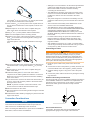
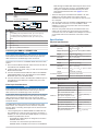
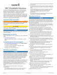
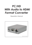
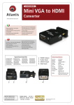
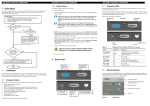
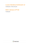
GMM™ Installation Instructions Important Safety Information WARNING See the Important Safety and Product Information guide in the product box for product warnings and other important information. When connecting the power cable, do not remove the in-line fuse holder. To prevent the possibility of injury or product damage caused by fire or overheating, the appropriate fuse must be in place as indicated in the product specifications. In addition, connecting the power cable without the appropriate fuse in place will void the product warranty. CAUTION Always wear safety goggles, ear protection, and a dust mask when drilling, cutting, or sanding. NOTICE When drilling or cutting, always check what is on the opposite side of the surface. Registering Your Device Help us better support you by completing our online registration today. • Go to http://my.garmin.com. • Keep the original sales receipt, or a photocopy, in a safe place. Contacting Garmin Product Support • Go to www.garmin.com/support and click Contact Support for in-country support information. • In the USA, call (913) 397.8200 or (800) 800.1020. • In the UK, call 0808 2380000. • In Europe, call +44 (0) 870.8501241. Tools Needed • • • • • Drill and drill bits #2 Phillips screwdriver Marine sealant Jigsaw File and sandpaper Mounting Considerations NOTICE This device should be mounted in a location that is not exposed to extreme temperatures or conditions. The temperature range for this device is listed in the product specifications. Extended exposure to temperatures exceeding the specified temperature range, in storage or operating conditions, may cause device failure. Extreme-temperature-induced damage and related consequences are not covered by the warranty. Using the included hardware and template, you can mount the device using one of two methods. You can use the included bracket and hardware to bail mount the device, or you can use the included template and hardware to flush mount the device in the dashboard. To mount the device so it appears flat with the front of the dashboard, you must purchase a flat-mount kit (sold May 2013 separately, with professional installation recommended) from your Garmin® dealer. When selecting a mounting location, observe these considerations. • The location should not be directly exposed to the elements. The rear housing of the device is not water or weatherresistant. • The location should provide optimal viewing as you operate your boat. • The location should allow for easy access to all device interfaces, such as the keypad, touchscreen, and card reader, if applicable. • The location must be strong enough to support the weight of the device and protect it from excessive vibration or shock. • To avoid interference with a magnetic compass, the device should not be installed closer to a compass than the compass-safe distance value listed in the product specifications. • The location must allow room for the routing and connection of all cables. Mounting the Device NOTICE Be careful when cutting the hole to flush mount the device. There is only a small amount of clearance between the case and the mounting holes, and cutting the hole too large could compromise the stability of the device after it is mounted. A blue rubber seal is included for each DVI port on the device. This seal must be installed between each DVI port and DVIcable connector to avoid damage to the connectors. A gray rubber seal is included for each VGA port on the device. This seal must be installed between each VGA port and VGAcable connector to avoid damage to the connectors. When installing the seal, the arrow on the side of the seal must point toward the device. The included template and hardware can be used to flush mount the device in your dashboard. To mount the device so the screen is flat with the dashboard, you must purchase a flatmount kit from your Garmin dealer. 1 Trim the template and make sure it fits in the location where you want to flush mount the device. 2 Remove the protective liner from the back of the template and adhere it to the location where you want to mount the device. 3 Using a 3/8 in. (9.5 mm) drill bit, drill one or more of the holes inside the corners of the solid line on the template to prepare the mounting surface for cutting. 4 Using a jigsaw, cut the mounting surface along the inside of the solid line indicated on the template. 5 Place the device in the cutout to test the fit. 6 If necessary, use a file and sandpaper to refine the size of the cutout. 7 After the device fits correctly in the cutout, ensure the mounting holes on the device line up with the larger 9/32 in. (7.2 mm) holes on the template. 8 If the mounting holes on the device do not line up, mark the new hole locations. 9 Using a 9/32 in. (7.2 mm) drill bit, drill the larger holes. 10 Starting in one corner of the template, place a nut plate À over the larger hole Á drilled in step 9. 190-01559-02_0C Printed in Taiwan The smaller 9/64 in. (3.5 mm) hole  on the nut plate should line up with the smaller hole on the template. If 11 the smaller 9/64 in. (3.5 mm) hole on the nut plate does not line up with the smaller hole on the template, mark the new location. 12 Repeat steps 10–11 for each of the nut plates along the sides of the device as indicated on the template. Using a 9/64 in. (3.5 mm) drill bit, drill the smaller holes. 13 14 Remove the template from the mounting surface. 15 Starting in one corner of the mounting location, place a nut plate à on the back of the mounting surface, lining up the large and small holes. The raised portion of the nut plate should fit into the larger hole. • Although it is recommended to use the Garmin provided DVI cables, high-quality third-party DVI cables may be used. Before a DVI cable is routed, it should be tested by connecting the devices with it. • The GMM device should be connected to the same power source as a connected GPSMAP 8500 device. If this is not possible, the devices must be connected to the same ground. • The power and ground connections to the battery must be checked to make sure they are secured and will not become loose. • The touchscreen functionality of the GMM device can be used to control one GPSMAP 8500 device. • The GMM device used to control a GPSMAP 8500 device must be connected to both the GARMIN PROCESSOR BOX and MAIN DVI VIDEO IN ports on the GMM and the GARMIN MONITOR and MAIN DVI-I VIDEO ports on the GPSMAP 8500 using a Garmin Marine Network cable and a DVI-D cable. • For easier cable routing, the power and Garmin Marine Network cables are packaged without the locking rings installed. The cables should be routed before the locking rings are installed. • After installing a locking ring on a cable, you should make sure the ring is securely connected and the o-ring is in place so the power or data connection remains secure. Connecting to Power WARNING When connecting the power cable, do not remove the in-line fuse holder. To prevent the possibility of injury or product damage caused by fire or overheating, the appropriate fuse must be in place as indicated in the product specifications. In addition, connecting the power cable without the appropriate fuse in place will void the product warranty. 16 Secure the nut plate to the mounting surface by fastening an included M3 screw Ä through the smaller 9/64 in. (3.5 mm) hole. 17 Repeat steps 15–16 for each of the nut plates along the sides of the device. 18 Install the rubber gasket Å on the back of the device. The pieces of the rubber gasket have adhesive on the back. Make sure you remove the protective liner before installing them on the device. 19 If you will not have access to the back of the device after you mount it, connect all necessary cables to the device before placing it into the cutout. NOTE: To prevent corrosion of the metal contacts, cover unused connectors with the attached weather caps. 20 Place the device into the cutout. 21 Secure the device to the mounting surface using the included M4 screws Æ. 22 Install the decorative bezel by snapping it in place around the edges of the device. 1 Route the power cable to the power source and to the device. Connect the red wire to the positive (+) battery terminal, and 2 connect the black wire to the negative (-) battery terminal. 3 Install the locking ring and o-ring on the end of the power cable. 4 Connect the power cable to the device by turning the locking ring clockwise. Additional Grounding Considerations This device should not need any additional chassis grounding in most installation situations. If interference is experienced, the grounding screw on the housing can be used to connect the device to the water ground of the boat to help avoid the interference. Connection Considerations NOTICE A blue rubber seal is included for each DVI port on the device. This seal must be installed between each DVI port and DVIcable connector to avoid damage to the connectors. When connecting the GMM device to power and to a GPSMAP® 8500 device, observe these considerations. 2 Power Cable Extensions If necessary, the power cable can be extended using the appropriate wire gauge for the length of the extension. Item Description Fuse À Á  Battery 6 ft. (1.8 m) no extension Item Description À Á Â Ã Ä Å Æ Splice • 10 AWG (5.26 mm²) extension wire, up to 15 ft. (4.6 m) • 8 AWG (8.36 mm²) extension wire, up to 23 ft. (7 m) • 6 AWG (13.29 mm²) extension wire, up to 36 ft. (11 m) Fuse 8 in. (20.3 cm) Battery 8500 through the MAIN DVI VIDEO IN port with a DVI-D cable, and it must also connect to the GPSMAP 8500 through the GARMIN PROCESSOR BOX port with a Garmin Marine Network cable. See page 3 for more information. • The three VGA ports are labeled VGA VIDEO 1 IN, VGA VIDEO 2 IN, and VGA VIDEO 3 IN. These ports use standard VGA connectors for connections to sources such as a computer. • The component-video port is labeled COMPONENT IN. This port uses BNC connectors. You can use BNC to RCA adapters to connect a component-video source with RCA connectors to this port. • The three composite-video ports are labeled CVBS 1 IN, CVBS 2 IN, and CVBS 3 IN. These three ports use BNC connectors. You can use a BNC to RCA adapter to connect a composite-video source with RCA connectors to these ports. Specifications Physical Specifications 8 in. (20.3 cm) Device 36 ft. (11 m) maximum extension GMM 150 Dimensions (W×H×D) Connecting the GMM to a GPSMAP 8500 NOTICE A blue rubber seal is included for each DVI port on the device. This seal must be installed between each DVI port and DVIcable connector to avoid damage to the connectors. This device can connect to a GPSMAP 8500 with touchscreen control. 1 Route a Garmin Marine Network cable and a DVI-D cable to the GMM and the GPSMAP 8500. 2 Install a locking ring and an o-ring on each end of the Garmin Marine Network cable. 3 Connect the Garmin Marine Network cable to the GARMIN PROCESSOR BOX port on the GMM and to the GARMIN MONITOR port on the GPSMAP 8500. 4 Connect the DVI-D cable to the MAIN DVI VIDEO IN port on the GMM and to the MAIN DVI-I VIDEO OUT port on the GPSMAP 8500. Video Input Considerations NOTICE A blue rubber seal is included for each DVI port on the device. This seal must be installed between each DVI port and DVIcable connector to avoid damage to the connectors. A gray rubber seal is included for each VGA port on the device. This seal must be installed between each VGA port and VGAcable connector to avoid damage to the connectors. When installing the seal, the arrow on the side of the seal must point toward the device. The GMM allows video input from two digital sources, three VGA sources, one component source, and three composite sources. When connecting video input sources, observe these considerations. • The two digital ports are labeled MAIN DVI VIDEO IN and DVI VIDEO 2 IN. These two ports use DVI-D connectors. If needed, you can use a DVI-D to HDMI adapter to connect to a HDMI-compatible video source. ◦ The MAIN DVI VIDEO IN port is designed for use with a GPSMAP 8500 device. ◦ To function as a touchscreen input device with a GPSMAP 8500, the GMM must connect to the GPSMAP Specification Measurement 1457/64 × 1263/64 × 15/16 in. (378.2 × 329.7 × 74.3 mm) Display size (W×H) 1131/32 in. × 863/64 in. (304.1 × 228.1 mm) Weight GMM 170 Dimensions (W×H×D) 9.572 lbs (4.342 kg) 1611/64 × 1439/64 × 231/32 in. (410.7 × 371.1 × 75.3 mm) Display size (W×H) 1041/64 in. × 1319/64 in. (270.3 × 337.9 mm) Weight GMM 190 Dimensions (W×H×D) 8.828 lbs (4.458 kg) 189/32 × 157/8 × 37/32 in. (464.3 × 403.1 × 81.8 mm) Display size (W×H) 1155/64 in. × 1413/16 in. (301.3 × 376.3 mm) Weight All models Material 11.982 lbs (5.435 kg) Aluminum sheet metal Temperature range From 5° to 122°F (from -15° to 50°C) Electrical Specifications Device Specification Measurement All models Input power 10–32 Vdc Fuse 15 A, 42 V fast-acting Max. power usage at 10 Vdc 30 W Typical current draw at 12 Vdc 2.4 A Max. current draw at 12 Vdc 2.5 A Compass-safe distance 315/16 in. (100 mm) Max. power usage at 10 Vdc 60 W Typical current draw at 12 Vdc 4.8 A Max. current draw at 12 Vdc 5 A Compass-safe distance 315/16 in. (100 mm) Max. power usage at 10 Vdc 120 W Typical current draw at 12 Vdc 9.8 A Max. current draw at 12 Vdc 10 A Compass-safe distance 131/32 in. (50 mm) GMM 150 GMM 170 GMM 190 3 Garmin®, the Garmin logo, and GPSMAP® are trademarks of Garmin Ltd. or its subsidiaries, registered in the USA and other countries. GMM™ is a trademark of Garmin Ltd. or its subsidiaries. These trademarks may not be used without the express permission of Garmin. Garmin International, Inc. 1200 East 151st Street Olathe, Kansas 66062, USA Garmin (Europe) Ltd. Liberty House, Hounsdown Business Park Southampton, Hampshire, SO40 9LR UK Garmin Corporation No. 68, Zhangshu 2nd Road, Xizhi Dist. New Taipei City, 221, Taiwan (R.O.C.) © 2013 Garmin Ltd. or its subsidiaries www.garmin.com/support