1
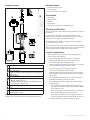
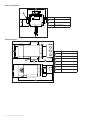
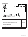
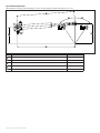
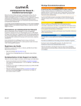
Important Safety Information Class B Drive Unit Installation Instructions To obtain the best performance and to avoid damage to your boat, install the Garmin® Class B Drive Unit according to the following instructions. Professional installation of the drive unit is highly recommended, because specific knowledge of rudder operation is required to properly install the drive unit. Warning You are responsible for the safe and prudent operation of your vessel. The Autopilot is a tool that will enhance your capability to operate your boat. It does not relieve you from the responsibility of safely operating your boat. Avoid navigational hazards and never leave the helm unattended. See the Important Safety and Product Information guide in the autopilot product box for product warnings and other important information. Read all installation instructions before proceeding with the installation. If you experience difficulty during the installation, contact Garmin Product Support. caution Failure to install and maintain this equipment in accordance with these instructions could result in damage or injury. About the Class B Drive Unit When in use, beware of hot motor and solenoid components, as well as the risk of entrapment from moving parts The Class B drive unit is a self-contained hydraulic drive unit that uses a solenoid clutch to extend and retract the rod that steers the tiller. Combined with the included rudder feedback sensor, the Garmin Class B Drive unit will provide the steering necessary for a Garmin autopilot when installed correctly. Always wear safety goggles, ear protection, and a dust mask when drilling, cutting, or sanding. Because the drive unit is self-contained, you do not need to connect or disconnect any of the hydraulic hoses. The system was filled and tested at the factory. This equipment is only for use with Garmin autopilots. Registering Your Device Help us better support you by completing our online registration today. Notice This equipment should be installed by a qualified marine installer. The system was filled and tested at the factory, so you should not disconnect the hydraulic hoses to install the system. When drilling or cutting, always check the opposite side of the surface. Be aware of fuel tanks, electrical cables, and hydraulic hoses. • Go to http://my.garmin.com. • Keep the original sales receipt, or a photocopy, in a safe place. Contacting Garmin Product Support Contact Garmin Product Support if you have any questions about this product. • In the USA, go to www.garmin.com/support, or contact Garmin USA by phone at (913) 397.8200 or (800) 800.1020. • In the UK, contact Garmin (Europe) Ltd. by phone at 0808 2380000. • In Europe, go to www.garmin.com/support and click Contact Support for in-country support. March 2011 190-01289-06 Rev. B Printed in the UK Package Contents Hardware Needed • Tiller arm (if needed, page 2) • End stops (page 2) • Screws to mount the reservoir (page 3) ➌ ➊ ➍ ➋ Tools Needed • • • • • Safety glasses Drill and drill bits Wrenches Torque wrench Loctite® 638™ or equivalent (recommended, page 4) Tiller Arm and End Stops You can connect the drive unit to either an existing quadrant or to a tiller arm (not included). If you do not have a quadrant or can not install the drive unit at your quadrant location, choose a tiller arm that fits the diameter of your rudder post and is the correct length for the installation location. ➎ ➏ ➊ ➋ ➌ ➍ ➎ ➏ ➐ ➑ The cylinder must not act as a drive limiter. Physical end stops (not included) must be in place to limit the cylinder-rod travel to 12 in. (305 mm) from fully retracted to fully extended, or damage to the cylinder will occur. ➐ ➑ Reservoir Cylinder/ram Tiller bolt and fittings Suitable for a quadrant or tiller arm thickness of .79 in. (20 mm) to .98 in. (25 mm) Rudder feedback kit Cylinder fasteners • M8 bolts, washers, and nuts • Suitable for mounting the cylinder on a surface between .47 in. (12 mm) and .95 in. (24 mm) thick Hydraulic oil Pump Pump fasteners M8 bolts, washers, and nuts Note: The fasteners listed above are used to secure the components to the packaging. Do not discard the hardware when unpacking the drive unit. 2 The supplied tiller bolt is suitable for a quadrant or tiller arm thickness of .79 in. (20 mm) to .98 in. (25 mm). Location Considerations When selecting a location to mount the cylinder, the pump, and the reservoir, consider these guidelines: • The system was filled and tested at the factory, so none of the hydraulic hoses should be disconnected to install the system. • The components must all be installed under deck. • The motor should not be installed in a location where it is exposed to excessive temperature (page 6), vibration, or fumes. Any of these extremes can reduce the life of the motor. • Avoid contact with water and excessive humidity. • Motor-brush holders are located on both sides of the motor, and the motor should be installed so that the motor brushes are accessible for service (page 3). • The cylinder must be mounted securely on a surface that is able to withstand the high thrusts generated by the rudder. • The cylinder must be installed within specific extension and angle limitations (page 8). ◦◦ The cylinder-rod movement must be limited by physical stops to 12 in. (305 mm) from fully retracted to fully extended, or damage to the cylinder will occur. ◦◦ No part of the cylinder or rod should contact the vessel, quadrant, or tiller arm throughout the full range of movement. ◦◦ The 5° angle at the extremes of the stroke (page 8) must not be exceeded, or damage the cylinder bearings and the rod will occur. An example illustration is available in the appendix (page 9). Class B Drive Unit Installation Instructions Installing the Reservoir Installing the Pump Notice The reservoir is fitted with a special cap that contains a breather hole. The breather hole is sealed for transit and must be opened before operation. Notice Do not disconnect the hydraulic hoses from the pump. The reservoir contains the hydraulic fluid necessary for operation of the drive unit, and it must be installed and prepared before installing any other components. Do not attempt to move the cylinder rod until instructed. You must first select a mounting location before you can install the reservoir (page 2). 1. Select fastening screws suitable for mounting the reservoir on a bulkhead of your boat. 2. Choose a location on a bulkhead as far above the pump and cylinder as possible and mark the pilot holes ➊. If needed, the device and mounting-hole dimensions are provided in the appendix (page 7). Bolts, washers, and nuts are provided to install the pump. You must first select a mounting location before you can install the pump (page 2). 1. Make sure that the brush holders ➊ are accessible for service after mounting the pump. ➊ ➋ ➋ ➊ 2. Mark the pilot hole locations ➋. If needed, the device and pilot hole dimensions are provided in the appendix (page 7). 3. Drill the mounting holes using a drill bit appropriate for the mounting surface and the mounting hardware. 4. Secure the pump to the mounting surface with the included hardware. Installing the Cylinder ➌ 3. 4. 5. 6. ➍ Drill the pilot holes using a drill bit appropriate for the chosen screws. Secure the reservoir to the bulkhead with the screws. Remove the transit screw and seal ➋ from the cap. Save the screw and seal for future use. Using the included hydraulic oil, fill the reservoir to the maximum level as indicated on the label. 7. Turn the valve from the OFF position ➌ to the ON position ➍. 8. Extend the cylinder rod halfway, and check the oil level. 9. If necessary, add oil. Notice The cylinder rod movement must be limited by physical end stops to 12 in. (305 mm) from fully retracted to fully extended. Failure to install steering end stops will damage the drive unit. Do not exceed the 5° angle at the extremes of the stroke (page 8). Exceeding the 5° angle at the extremes of the stroke will damage the cylinder bearings and the rod. You must first select a mounting location before you can install the cylinder (page 2). 1. Install the mounting foot (page 3). 2. Install the tiller bolt (page 4). Installing the Mounting Foot The mounting foot is at the base of the cylinder. Hardware is supplied to fasten the mounting foot to the mounting surface. The supplied M8 bolts, washers, and nuts are suitable for mounting the cylinder on a surface between .47 in. (12 mm) and .95 in. (24 mm) thick. 1. With the mounting foot in the chosen location, mark the locations of the four mounting holes on the mounting surface. Class B Drive Unit Installation Instructions 3 2. Verify the marked locations. The marked locations should be 3 in. (76.2 mm) ➊ apart. NOTE: The diagram is not to scale. 3. Drill .35 in. (8.8 mm) holes through the mounting surface. 4. Secure the mounting foot to the mounting surface using the supplied M8 bolts, washers, and nuts. 5. Tighten the bolts to 12.5 ft-lbf (17 Nm). ➑ ➒ ➐ ➊ ➏ ➋ ➊ ➊ ➌ Installing the Tiller Bolt The supplied tiller bolt is suitable for a quadrant or tiller arm thickness of .79 in. (20 mm) to .98 in. (25 mm). ➍ ➎ 1. Drill a 20.1 mm hole in the quadrant or tiller arm ➊ (not included) for the tiller bolt ➋. ➑ ➐ ➏ ➋ ➌ ➊ ➍ ➎ 2. It is recommended to apply Loctite 638 or equivalent to the tiller bolt where it passes through the quadrant or tiller arm ➌. 3. Place the tiller bolt into the quadrant or tiller arm, and secure it with the M20 washer ➍ and the M20 nut ➎. 4. Tighten the M20 nut to 50.15 ft-lbf (68 Nm). 5. Place the rod ➏ on the tiller bolt. 6. Fasten the rod to the tiller bolt with the other M20 washer ➐ and the locking pin ➑. Installing the Rudder Feedback Sensor Notice You must carefully measure the operating distance of the drive unit cylinder rod and install the feedback sensor mounting clamp at the proper location, or you will damage the feedback sensor. To use the drive unit with a Garmin autopilot, you must install the rudder feedback sensor after you have installed the drive unit. 2. Fasten the sensor mounting clamp to the cylinder using the included 45 mm M6 screw ➌ and M6 nut ➍. Do not tighten the nut at this time. 3. Adjust the position of the sensor mounting clamp so that the distance ➎ between the mounting bracket and the center of the tiller bolt is between 19.69 in. (500 mm) and 32.28 in. (820 mm) during the full range of the cylinder movement. If the distance ever compresses below 19.69 in. (500 mm) or extends beyond 32.28 in. (820 mm) it will damage the sensor. 4. Tighten the M6 nut to 3.7 ft-lbf (5 Nm). 5. Install the sensor mounting stud ➏ in the sensor mounting clamp. 6. Fit the rudder feedback sensor ➐ on the sensor mounting clamp and the tiller bolt. 7. Fasten the rudder feedback sensor to the sensor mounting clamp with the included M5 A4 washer ➑ and locking pin ➒. 8. Fasten the rudder feedback sensor to the tiller bolt with the included M5 A4 washer and locking pin. Connecting the Drive Unit to the Garmin Autopilot Notice Do not cut the cables connected to the drive unit. Cutting the drive-unit cables voids your warranty. Consult the installation instructions provided with your Garmin autopilot to install the autopilot components and to connect the drive unit to the correct component. 1. Place the sensor mounting clamp ➊ on the cylinder ➋. 4 Class B Drive Unit Installation Instructions Maintenance and Service General Maintenance • To maximize the life of your drive unit, take the following precautions: ◦◦ Keep the cylinder rod free from damage. ◦◦ Avoid exposing the drive unit to salt water. • Perform the following tasks on a regular basis: ◦◦ Inspect the cylinder-mounting-foot hardware and the tiller-bolt hardware. If necessary, tighten any components. ◦◦ Lubricate the cylinder rod-end and the tiller bolt. Use only high-quality marine grease that is compatible with nitrile seals. Inspecting the Motor Brushes You should inspect the motor brushes every 500 hours (typically annually) for wear. 1. Remove the brush holder on the side of the motor. 2. Inspect the brushes for wear. 3. If necessary, purchase replacement brushes. Replacing the Motor Brushes Replace the brushes with the correct replacement part while following these guidelines: • Clean all of the loose carbon from the inside the motor before fitting the new brushes in the motor. • If hydraulic fluid has entered the motor, correct the cause, and then degrease the brush gear and commutator before running the motor. If you do not degrease the motor in this situation, arching will reduce the bush life. Bleeding the System 6. Slowly pull out the cylinder rod until it is fully extended. 7. Observe the oil level in the reservoir. 8. If necessary, fill the reservoir to the minimum line on the label. 9. Fully retract the rod. The oil level will rise when the rod is retracted. 10.Observe the oil level in the reservoir. 11.If necessary, fill the reservoir to the maximum line on the label. 12.Repeat steps 6–11 until you can see no air rising into the reservoir, and the pump takes over. 13.Use the autopilot to extend and retract the rod until you can see no air rising into the reservoir. You may need to manually assist the cylinder at first to purge any remaining air in the system. 14.Observe the oil level in the reservoir. 15.If necessary, fill the reservoir to the maximum line on the label. Troubleshooting Symptom The motor does not run. Possible Causes • The power and clutch cable is not connected to the ECU. • The rudder-feedback cable is not connected to the ECU. • The motor brushes need to be replaced (page 5). The motor runs, but There is air in the cylinder (may be accompanied by the cylinder rod does external oil loss). Bleed the system (page 5). not move or moves erratically. The pump makes • There is air in the cylinder (may be accompanied excessive noise. by external oil loss). Bleed the system (page 5). • The motor may be damaged. Caution When bleeding the system, stay clear of moving steering components and linkages at all times to avoid injury. Notice Before bleeding the system, make sure the oil and any storage containers are clean and free of contamination to avoid damaging the drive unit. The hydraulic system of the drive unit was filled and tested at the factory, so follow this procedure only if air has entered the system or if the system has been dismantled. Before you can bleed the system, you must purchase the correct type of hydraulic oil (page 6). Dispose of any waste oil responsibly. 1. 2. 3. 4. 5. Set the reservoir tap to the ON position (page 3). Push in the cylinder rod so that it is fully retracted. Loosen, but do not disconnect, the reservoir hoses from the cylinder. Oil will emerge from the connectors when loosened properly. Tighten the hoses. Turn on the autopilot system to energize the drive unit. Class B Drive Unit Installation Instructions 5 Appendix Specifications Component Motor Clutch Cylinder Oil Ports Specification Nominal output power Maximum continuous current Rotation Protection Ignition protection EMC Coil voltage nominal Coil power continuous Protection Volume (Nominal) Area Stroke Adjustment Maximum thrust (intermittent) Hard over time nominal Relief valve setting Cylinder body material Cylinder rod material Seals Body Protection Recommended Equivalent Hoses Pump Cylinder Threads Material Type General Length System Weight (Gross) Temperature rating 6 Value 100 W 12 A Reversing IP55 BS EN 28846:1993 BS EN 60945: 2002 12 Vdc 12 W IP65 0.44 gal. (538 cc) 0.27 in² (176.6 mm²) 12 in. (305 mm) 0.7 in. (18 mm) 2,469 lbs (1120 kg) 13 sec. 62 bar Aluminium BS 1490 Stainless Steel Chrome Plated Nitrile & PTFE SP270 Q8 Dynobear 10 Mineral based hydraulic Minimum – ISO VG10 Maximum – ISO VG40 G1/4(BSP) parallel BS2779’73 G1/4(BSP) parallel BS2779’73 5/8-18 SAE female swivel Brass Marine Steering Hose • 1000 PSI working pressure • 5/16″ I/D 3.28 ft. (1 m) 30.86 lbs. (14 kg) From -4° to 149°F (from -20º to 65ºC) Class B Drive Unit Installation Instructions Reservoir Dimensions ➊ ➋ Item ➊ ➋ ➌ ➌ Measurement 5.85 in. (148.7 mm) 3/8 in. (9.5 mm) diameter 2.18 in. (55.3 mm) Pump Dimensions ➊➋ Item ➏ ➊ ➋ ➌ ➍ ➎ ➏ ➐ ➌ ➍ ➎ Measurement 3.5 in. (88.9 mm) 2.68 in. (68 mm) diameter 0.28 in. (7 mm) diameter 2 in. (50.8 mm) 3.33 in. (84.6 mm) 3.15 in. (80 mm) 8.58 in. (218 mm) ➐ Class B Drive Unit Installation Instructions 7 Cylinder Installation Dimensions ➊ ➋ B A ➌ ➍ ➎ ➑ ➑ ➐ ➏ ➏ Item Description Pivot radius of the cylinder on the mounting foot. ➊ ➋ ➌ ➍ ➎ ➏ ➐ ➑ ➒ ➓ 8 ➒ ➓ Measurement 360° Stroke distance from fully retracted to fully extended. 12 in. (305 mm) Distance from the center of the cylinder mount to the rudder bolt when fully retracted. 23.75 in. (603.2 mm) Distance from the center of the cylinder mount to the rudder bolt when the rudder is amidships. 29.72 in. (754.9 mm) Distance from the center of the cylinder mount to the rudder bolt when the rod is fully extended. 35.7 in. (906.8) Maximum tilt angle of the cylinder when at the extremes of the stroke. Exceeding this angle will damage the drive unit. Maximum adjustable distance of the rudder bolt adapter from the end of the rod. 5° to either side of center Maximum tilt angle of the rudder bolt when at the extremes of the stroke. 10° to either side of center Thickness of the rudder bolt adapter. 0.98 in. (24.9 mm) Relative distance from the center of the rod to the base of the cylinder mount when at rest. 2 in. (51 mm) 0.59 in. (15 mm) Class B Drive Unit Installation Instructions Cylinder Mounting Example This example shows a typical cylinder installation on a 8.4 in. (214 mm) quadrant with total rudder angle of 70° (2 × 35°). ➊ ➋ ➋ ➍ ➌ ➎ Item ➊ ➋ ➌ ➍ ➎ Description Distance from the center of the cylinder base to the tiller bolt when the rudder is amidships. Measurement 29.66 in. (753.3 mm) Degree of travel from amidships to the installed cylinder stops. 35° Relative distance from the center of the cylinder base to the rudder post. 8.28 in. (210.4 mm) Distance from the center of the tiller bolt to the rudder post. 10.12 in. (257 mm) Distance from the center of the cylinder base to the rudder post when the rudder is amidships. 29.67 in. (753.7 mm) Class B Drive Unit Installation Instructions 9 © 2011 Garmin Ltd. or its subsidiaries All rights reserved. Except as expressly provided herein, no part of this manual may be reproduced, copied, transmitted, disseminated, downloaded or stored in any storage medium, for any purpose without the express prior written consent of Garmin. Garmin hereby grants permission to download a single copy of this manual onto a hard drive or other electronic storage medium to be viewed and to print one copy of this manual or of any revision hereto, provided that such electronic or printed copy of this manual must contain the complete text of this copyright notice and provided further that any unauthorized commercial distribution of this manual or any revision hereto is strictly prohibited. Information in this document is subject to change without notice. Garmin reserves the right to change or improve its products and to make changes in the content without obligation to notify any person or organization of such changes or improvements. Visit the Garmin Web site (www.garmin.com) for current updates and supplemental information concerning the use and operation of this and other Garmin products. Garmin® and the Garmin logo are trademarks of Garmin Ltd. or its subsidiaries, registered in the USA and other countries. These trademarks may not be used without the express permission of Garmin. Loctite® 638™ is a trademark of Henkel Corporation in the U.S. and elsewhere. © 2011 Garmin Ltd. or its subsidiaries Garmin International, Inc. 1200 East 151st Street, Olathe, Kansas 66062, USA Garmin (Europe) Ltd. Liberty House, Hounsdown Business Park, Southampton, Hampshire, SO40 9LR UK Garmin Corporation No. 68, Zhangshu 2nd Road, Xizhi Dist., New Taipei City, 221, Taiwan (R.O.C.) www.garmin.com