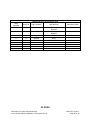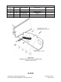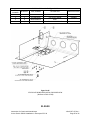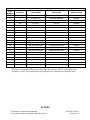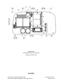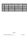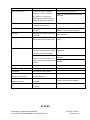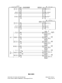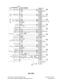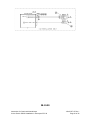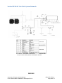
1
Instructions for Continued Airworthiness
for the Garmin G500H Installation in Eurocopter EC130
Garmin International, Inc.
1200 E. 151st Street
Olathe, Kansas 66062 USA
Dwg. Number:
190-01527-15 Rev. 1
Confidential
This drawing and the specifications contained herein
are the property of Garmin Ltd. or its subsidiaries and
may not be reproduced or used in whole or in part as
the basis for manufacture or sale of products without
written permission.
Rev.
Date
1
04/22/2014
Initial release.
Note: Document was RSG P/N 16E08310001 Rev. E
Description of Change
Table of Contents
CHAPTER 1 .................................................................................................................................. 4
Section 01-00-00
Introduction ......................................................................................................... 4
CHAPTER 4 .................................................................................................................................. 5
Section 04-00-00
Airworthiness Limitations .................................................................................. 5
CHAPTER 5 .................................................................................................................................. 6
Section 05-00-00
Continued Airworthiness Inspections ................................................................ 6
Section 05-20-10
Continued Airworthiness Scheduled Inspections .............................................. 9
Section 05-20-20
Continued Airworthiness Special Inspections ................................................... 17
CHAPTER 6 .................................................................................................................................. 19
Section 06-00-00
Dimensions and Access ....................................................................................... 19
CHAPTER 8 .................................................................................................................................. 27
Section 8-00-00
Weight and Balance Information ........................................................................ 27
CHAPTER 11 ................................................................................................................................ 28
Section 11-00-00
Placards and Markings ........................................................................................ 28
CHAPTER 12 ................................................................................................................................ 30
Section 12-00-00
Servicing Maintenance Practices ........................................................................ 30
Section 12-10-00
Return-to-Service Practices ................................................................................ 31
Section 12-20-00
Calibration Requirements ................................................................................... 32
CHAPTER 20 ................................................................................................................................ 33
Section 20-00-00
Standard Practices ............................................................................................... 33
Section 20-10-00
Torques Maintenance Practices .......................................................................... 34
Section 20-30-00
Painting Maintenance Practices .......................................................................... 38
Section 20-40-00
Corrosion Control Maintenance Practices .......................................................... 39
Section 20-90-00
Dye Penetrant Inspection Methods ..................................................................... 42
CHAPTER 31 ................................................................................................................................ 43
Section 31-00-00
Instruments ......................................................................................................... 43
CHAPTER 98 ................................................................................................................................ 68
Instructions for Continued Airworthiness
for the Garmin G500H Installation in Eurocopter EC130
190-01527-15 Rev 1
Page 2 of 82
Section 98-00-00
Wiring Diagrams and Pitot-Static System Schematics ....................................... 68
Section 98-10-00
Wiring Diagrams .................................................................................................. 69
Section 98-20-00
Pitot-Static System Schematic ............................................................................. 82
Instructions for Continued Airworthiness
for the Garmin G500H Installation in Eurocopter EC130
190-01527-15 Rev 1
Page 3 of 82
CHAPTER 1
Section 01-00-00 Introduction
These are accepted Instructions for Continued Airworthiness for modifications performed in
accordance with Eurocopter EC130 B4 Garmin G500H Flight Display System Installation STC. All
references to the G500H in this document will refer to the Garmin G500H Flight Display System
Installation and other related components specified in these Instructions for Continued
Airworthiness (ICA). A STC permission letter and Instructions for Continued Airworthiness (ICA)
should be supplied to the owner/operator of the STC at the time of completion. Subsequent
accepted changes to the ICA will be distributed to owners and operators of the STC.
This Instructions for Continued Airworthiness is intended to supplement the Model EC130 B4
rotorcraft maintenance manuals provided by Eurocopter. The information, procedures,
requirements, and limitations contained in this Instructions for Continued Airworthiness for this
type design change supersedes the information, procedures, requirements, and limitations
contained in the rotorcraft’s maintenance manual when the type design change is installed on
the Type Certificate Holder’s rotorcraft.
01-00-00
Instructions for Continued Airworthiness
for the Garmin G500H Installation in Eurocopter EC130
190-01527-15 Rev 1
Page 4 of 82
CHAPTER 4
Section 04-00-00 Airworthiness Limitations
There are no additional Airworthiness Limitations as defined in 14 CFR Part 27, Appendix A.
A27.4 that result from this modification. The Airworthiness Limitations section is FAA approved
and specifies inspections and other maintenance required under 14 CFR §§ 43.16 and 91.403
of the Federal Aviation Regulations unless an alternative program has been FAA approved.
04-00-00
Instructions for Continued Airworthiness
for the Garmin G500H Installation in Eurocopter EC130
190-01527-15 Rev 1
Page 5 of 82
CHAPTER 5
Section 05-00-00 Continued Airworthiness Inspections
1. General
This chapter contains time limit intervals for the Component Overhaul Schedule and Scheduled
Inspections for the G500H Installation. This chapter is to be added to the approved scheduled
inspection for the rotorcraft.
2. Component Overhaul Schedule
The system does not require overhaul at a specific time period. Power on self-test and
continuous BIT will monitor the health of the G500H system. If any LRU indicates an internal
failure, the unit may be removed and replaced.
3. Scheduled Inspections Overview
The G500H Installation requires a 90 Day Inspection that must be performed 90 days after
installation and then afterwards within 90 days of the last G500H Installation 90 day inspection.
The 90 Day Inspection requirements are specified in Table 5-01.
The G500H Installation requires an Annual Inspection that must be performed within 1 year (12
months) of initial installation and then afterwards within 1 year (12 months) of the last G500H
Installation annual inspection. The annual inspection requirements are specified in Table 5-02.
The G500H Installation requires a 5 Year Inspection that must be performed within 60 months
of initial installation and then afterwards within 60 months of the last G500H Installation
inspection. The 5 Year Inspection requirements are specified in Table 5-03.
The G500H Installation requires a 10 Year/2000 Flight Hours Inspection that must be performed
within 120 months or 2000 flight hours, whichever occurs first, of initial installation and then
afterwards within 120 months or 2000 flight hours, whichever occurs first, of the last G500H
Installation 10 year/2000 flight inspections. The 10 Year/2000 Flight Hour Inspection
requirements are specified in Table 5-04.
4. Special Inspection Practices
Conditions may arise from incidents or accidents that may warrant additional inspection
requirements. A Special Inspection is required if the aircraft is involved in a hard landing or is
subjected to total immersion in water. If either of these conditions occurs, the G500H
Installation must be inspected using the same procedures called out in the Annual Inspection
Procedures in Table 5-02.
05-00-00
Instructions for Continued Airworthiness
for the Garmin G500H Installation in Eurocopter EC130
190-01527-15 Rev 1
Page 6 of 82
The G500H Installation has a Post-Lightning Strike Inspection that must be performed in the
event of a suspected or actual lightning strike to the aircraft. The Post-Lightning Strike
Inspection requirements are specified in Table 5-05.
5. Definitions and Acronyms
The following is short descriptions of words and terms used in the procedures for the required
scheduled inspections.
•
Examine – Look carefully to find the condition of the component. Find how that condition
is related to a specific standard.
•
Condition – The state of an item or component compared to a known standard.
•
Standard – A specified rule or measure that is used to find the condition of a component.
•
Damage – Physical deterioration of a component.
•
Inspection – A procedure that includes checking, inspecting, and examining a system or
component.
•
Scheduled Inspection – An inspection procedure that must occur at a specified calendar
interval or at specified operational time intervals. Scheduled Inspections are required to
help ensure the rotorcraft stays airworthy.
•
Maintenance – The servicing and / or repair of a rotorcraft, a system, or a component that
keeps it serviceable.
•
Security – Term used for inspection of hardware and components to make sure they are
properly attached and tightened.
Acronyms
FOVICAPFDMFDVOMGDCGRSGMUGDU-
Field of View
Instructions for Continued Airworthiness
Primary Flight Display
Multifunction Display
Volt Ohm Meter
Garmin Data Computer
Garmin Reference System
Garmin Magnetometer Unit
Garmin Display Unit
05-00-00
Instructions for Continued Airworthiness
for the Garmin G500H Installation in Eurocopter EC130
190-01527-15 Rev 1
Page 7 of 82
OATGTPADCSTCAHRS-
Outside Air Temperature
Garmin Temperature Probe
Air Data Computer
Supplemental Type Certificate
Attitude Heading Reference System
05-00-00
Instructions for Continued Airworthiness
for the Garmin G500H Installation in Eurocopter EC130
190-01527-15 Rev 1
Page 8 of 82
Section 05-20-10 Continued Airworthiness Scheduled Inspections
1. General
This section contains requirements for scheduled inspections. Also included is a list of special
tools required to perform the scheduled inspections. If any part of the installation appears to
be functioning improperly, consult the troubleshooting guide. If a major component is
damaged or continues to malfunction, the component in question should be returned to the
manufacturer for replacement.
2. Scheduled Inspection Program
The G500H Installation requires scheduled inspections in order to maintain continued
airworthiness. Every effort should be made to perform the inspections with the aircraft placed
in a clean well lit environment. There are four different scheduled inspections required for the
G500H Installation.
a) 90 Day Inspection
The 90 day inspection is required to be performed every 90 day period of calendar elapsed
time, regardless of hours of operation. Inspection Table 5-01 the requirements of the 90 day
inspection.
b) 1 Year (Annual) Inspection
The 1 year (annual) inspection is required to be performed every 1 year period of calendar
elapsed time, regardless of hours of operation. Inspection Table 5-02 the requirements of the
1 year (annual) inspection.
c) 5 Year Inspection
The 5 year inspection is required to be performed every 5 year period of calendar elapsed
time, regardless of hours of operation. Inspection Table 5-03 the requirements of the 5 year
inspection
d) 10 Year / 2000 Flight Hours
The 10 year /2000 Flight Hour inspection is required to be performed at a 10 year period of
calendar elapsed time, or at 2000 flight hours of operation, whichever occurs first. Inspection
Table 5-04 specifies the requirements of the 10 year/2000 flight hour inspection.
3. Tools and Special Tools for Scheduled Inspection
Although not necessarily considered special tools, the adjustable ball swivel mirror and bright
flashlight and / or drop light are standard requirements for doing inspections. These items
should be used freely and frequently to enhance inspection quality and help ensure
05-20-10
Instructions for Continued Airworthiness
for the Garmin G500H Installation in Eurocopter EC130
190-01527-15 Rev 1
Page 9 of 82
discrepancies are not missed. It is important to have adequate lighting for all phases of the
inspection.
The special tools necessary for the G500H inspection are listed as follows:
a) Milliohm meter (for electrical bonding testing).
Table 5-01 -90 Day Inspection
Registration No.
Serial No.
Helicopter Total Hours
90 Day Scheduled Inspection
•
•
•
•
The 90 Day Inspection shall be accomplished at least at an interval of once every 90 days of
elapsed calendar time.
Initial each item after accomplishing the inspection.
Record all findings and attach a copy of findings to this inspection form.
After correction of all findings, make maintenance record entry.
90 Day Pre-inspection
Requirement
Initial
1. Review Airworthiness Directives.
90 Day Inspection
Requirement
Initial
GDC 74H ADC
1. Access GDC 74H (reference Section 6-00-00- Dimensions and Access). Drain the pitotstatic system by removing the safety wire, nut and plug.
2. Re-install the plug, nut and safety wire.
3. Reference Section 12-10-00 Return-to-Service Practices for the GDC 74H
05-20-10
Instructions for Continued Airworthiness
for the Garmin G500H Installation in Eurocopter EC130
190-01527-15 Rev 1
Page 10 of 82
Table 5-02 -1 year (Annual) Inspection
Registration No.
Serial No.
Helicopter Total Hours
1 Year (Annual) Scheduled Inspection
•
•
•
•
The 1 Year inspection shall be accomplished at least at an interval of once every year of elapsed
calendar time.
Initial each item after accomplishing the inspection.
Record all findings and attach a copy of findings to this inspection form.
After correction of all findings, make maintenance record entry.
1 year (Annual) Pre-inspection
Requirement
Initial
1. Review Airworthiness Directives.
1 year (Annual) Inspection
Requirement
Initial
GDU 620
1. Locate GDU 620 (reference Section 6-00-00 Access and Dimension). Inspect all knobs
and buttons for legibility.
2. Inspect instrument panel for damage, corrosion, and security. If damaged, replace
damaged or cracked Instrument panel. Treat and repair corrosion as required in Section
20-40-00 Corrosion Control Maintenance Practices. Tighten any loose hardware to values
listed in Section 20-10-00.
3. Inspect unit for security of attachment. Replace the damaged or corroded hardware.
Replace any missing hardware. Torque all screws in accordance with Section 20-10-00
Torques Maintenance Practice.
4. Conduct visual inspection of wires, backshells, and connectors looking for signs of wear,
deterioration or damage. Replace as required.
5. Inspect harness connections in back of unit. Secure any loose connections and support
unsecure wiring harness with additional clamping and / or tie rap supports if required.
GRS 77H AHRS
1. Access GRS 77H (reference Section 6-00-00- Dimensions and Access). Inspect AHRS and
mount for physical damage cracks, and corrosion. Treat and repair corrosion as required in
Section 20-40-00 Corrosion Control Maintenance Practices.
05-20-10
Instructions for Continued Airworthiness
for the Garmin G500H Installation in Eurocopter EC130
190-01527-15 Rev 1
Page 11 of 82
2. Conduct visual inspection of wires, backshells, and connectors looking for signs of wear,
deterioration or damage. Replace as required.
3. Inspect harness connections in back of unit. Secure any loose connections and support
unsecure wiring harness with additional clamping and / or tie rap supports if required.
4. Inspect unit for security of attachment. Replace the damaged or corroded hardware.
Replace any missing hardware. Torque all screws in accordance with Section 20-10-00
Torques Maintenance Practice.
GMU 44 Magnetometer Installation
1. Access GMU 44 (reference Section 6-00-00- Dimensions and Access). Inspect GMU 44
and mount for physical damage cracks, and corrosion. Treat and repair corrosion as
required in Section 20-40-00 Corrosion Control Maintenance Practices.
2. Conduct visual inspection of wires, backshells, and connectors looking for signs of wear,
deterioration or damage. Replace as required.
3. Inspect hardware. Replace the damaged or corroded hardware. Replace any missing
hardware. Torque all screws in accordance with Section 20-10-00 Torques Maintenance
Practice.
4. Inspect harness connections in back of unit. Secure any loose connections and support
unsecure wiring harness with additional clamping and / or tie rap supports if required.
Shelf Installation
1. Access Shelf Installation (reference Section 6-00-00- Dimensions and Access). Inspect for
physical damage cracks, and corrosion. Treat and repair corrosion as required in Section 2040-00 Corrosion Control Maintenance Practices
2. Inspect hardware. Replace the damaged or corroded hardware. Replace any missing
hardware. Torque all screws in accordance with Section 20-10-00 Torques Maintenance
Practice.
GDC 74H ADC Installation
1. Access GDC 74H (reference Section 6-00-00- Dimensions and Access). Inspect GDC 74H
and mount for physical damage cracks, and corrosion. Treat and repair corrosion as
required in Section 20-40-00 Corrosion Control Maintenance Practices.
2. Inspect unit for security of attachment. Replace the damaged or corroded hardware.
Replace any missing hardware. Torque all screws in accordance with Section 20-10-00
Torques Maintenance Practice.
3. Conduct visual inspection of wires, backshells, and connectors looking for signs of wear,
deterioration or damage. Replace as required.
4. Inspect harness connections in back of unit. Secure any loose connections and support
unsecure wiring harness with additional clamping and / or tie rap supports if required.
5. Inspect Pitot-Static System for damage. Replace parts as needed. Complete the 90 Day
Inspection found in Table 5-01.
05-20-10
Instructions for Continued Airworthiness
for the Garmin G500H Installation in Eurocopter EC130
190-01527-15 Rev 1
Page 12 of 82
GTP 59 OAT Probe Installation
1. Access GTP 59 OAT Probe (reference Section 6-00-00- Dimensions and Access). Inspect
GTP 59 OAT and mount for physical damage cracks, and corrosion. Treat and repair
corrosion as required in Section 20-40-00 Corrosion Control Maintenance Practices.
2. Inspect harness connections in back of unit. Secure any loose connections and support
unsecure wiring harness with additional clamping and / or tie rap supports if required.
3. Inspect unit for security of attachment. Replace the damaged or corroded hardware.
Replace any missing hardware. Torque all screws in accordance with Section 20-10-00
Torques Maintenance Practice.
Terminal Block Installation
1. Access Terminal Block Installation (reference Section 6-00-00- Dimensions and Access).
Inspect installation for physical damage cracks, and corrosion. Treat and repair corrosion as
required in Section 20-40-00 Corrosion Control Maintenance Practices.
2. Inspect unit for security of attachment. Replace the damaged or corroded hardware.
Replace any missing hardware. Torque all screws in accordance with Section 20-10-00
Torques Maintenance Practice.
Cooling Fan Installation (If option is installed)
1. Access Cooling Fan Installation (reference Section 6-00-00 Dimensions and Access).
Inspect installation for physical damage, cracks, and corrosion. Treat and repair corrosion as
required in Section 20-40-00 Corrosion Control Maintenance Practices.
2. Inspect cooling fan hoses for physical damage and security. Repair or replace any
damaged hoses. Replace any damaged or missing Tywraps
3. Inspect unit for security of attachment. Replace the damaged or corroded hardware.
Replace any missing hardware. Torque all screws in accordance with Section 20-10-00
Torques Maintenance Practices.
05-20-10
Instructions for Continued Airworthiness
for the Garmin G500H Installation in Eurocopter EC130
190-01527-15 Rev 1
Page 13 of 82
Table 5-03 -5 Year Inspection
Registration No.
Serial No.
Helicopter Total Hours
5 Year Scheduled Inspection
•
•
•
•
The 5 Year Inspection shall be accomplished at least at an interval of once every 5 years of
elapsed calendar time.
Initial each item after accomplishing the inspection.
Record all findings and attach a copy of findings to this inspection form.
After correction of all findings, make maintenance record entry.
5 Year Pre-inspection
Requirement
Initial
1. Review Airworthiness Directives.
5 Year Inspection
Requirement
Initial
GRS 77H AHRS
1. The GRS 77 utilizes an Earth magnetic field model which is updated once every five years
as part of the Aviation Database maintained by the owner/operator. If the magnetic model
is not current, the unit will issue an alert upon startup indicating the model has expired. The
model can be updated by inserting an aviation database card with an updated IGRF model
and powering on the system. A prompt will direct the user to press ENT to update the
model.
05-20-10
Instructions for Continued Airworthiness
for the Garmin G500H Installation in Eurocopter EC130
190-01527-15 Rev 1
Page 14 of 82
Table 5-04 -10 Year/2000 Flight Hour Inspection
Registration No.
Serial No.
Helicopter Total Hours
10 Year/ 2000 Flight Hour Scheduled Inspection
•
•
•
•
The 10 Year/ 2000 Flight Hour Inspection shall be accomplished at least at an interval of once
every 10 years of elapsed calendar time or 2000 Flight Hours, whichever occurs first.
Initial each item after accomplishing the inspection.
Record all findings and attach a copy of findings to this inspection form.
After correction of all findings, make maintenance record entry.
10 Year/2000 Flight Hour Pre-inspection
Requirement
Initial
1. Review Airworthiness Directives.
10 Year/2000 Flight Hour Inspection
Requirement
Initial
GRS 77H AHRS
1. Access GRS 77H, (Reference Section 6-00-00 Dimensions and Access) and disconnect all
harness connectors.
2. Measure the resistance between the GRS 77H and a nearby exposed portion of aircraft
metallic structure. Verify that the resistance is less than or equal to 20 milliohms. If greater
must be restored to the value specified in the G500H STC Installation Manual.
3. Reconnect all disconnected harness connectors and ensure they are secure.
GDU 620
4. Access GDU 620, (Reference Section 6-00-00 Dimensions and Access) and disconnect all
harness connectors.
5. Measure the resistance between the GDU 620 and a nearby exposed portion of aircraft
metallic structure. Verify that the resistance is less than or equal to 40 milliohms. If greater
must be restored to the value specified in the G500H STC Installation Manual.
6. Reconnect all disconnected harness connectors and ensure they are secure.
05-20-10
Instructions for Continued Airworthiness
for the Garmin G500H Installation in Eurocopter EC130
190-01527-15 Rev 1
Page 15 of 82
GDC 74H ADC
7. Access GDC 74H, (Reference Section 6-00-00 Dimensions and Access) and disconnect all
harness connectors.
8. Measure the resistance between the GDC 74H and a nearby exposed portion of aircraft
metallic structure. Verify that the resistance is less than or equal to 20 milliohms. If greater
must be restored to the value specified in the G500H STC Installation Manual.
9. Reconnect all disconnected harness connectors and ensure they are secure.
GMU 44
10. Access GMU 44, (Reference Section 6-00-00 Dimensions and Access) and disconnect all
harness connectors.
11. Measure the resistance between the GMU 44 and a nearby exposed portion of aircraft
metallic structure. Verify that the resistance is less than or equal to 20 milliohms. If greater
must be restored to the value specified in the G500H STC Installation Manual.
12. Reconnect all disconnected harness connectors and ensure they are secure.
GTP 59
13. Access GTP 59, (Reference Section 6-00-00 Dimensions and Access) and disconnect all
harness connectors.
14. Measure the resistance between the GTP 59 and a nearby exposed portion of aircraft
metallic structure. Verify that the resistance is less than or equal to 5 milliohms. If greater
must be restored to the value specified in the G500H STC Installation Manual.
15. Reconnect all disconnected harness connectors and ensure they are secure.
4. Post Inspection Maintenance Practices
After completion of the 1 Year (Annual) Inspection, 5 Year Inspection and 10 Year/2000 Flight
Hour Inspection and all discrepancies found have been corrected, the Return-to-Service
Practices (Reference Section 12-00-00 Return-to-Service Practices) should be accomplished in
preparation for returning the rotorcraft to service
05-20-10
Instructions for Continued Airworthiness
for the Garmin G500H Installation in Eurocopter EC130
190-01527-15 Rev 1
Page 16 of 82
Section 05-20-20 Continued Airworthiness Special Inspections
1. General
This section contains requirements for special inspections. Also included is a list of special tools
required to perform the scheduled inspections. If any part of the installation appears to be
functioning improperly, consult the troubleshooting guide. If a major component is damaged or
continues to malfunction, the component in question should be returned to the manufacturer
for replacement.
2. Special Inspection Program
Conditions may arise from incidents or accidents that may warrant additional inspection
requirements. A Special Inspection is required if the aircraft is involved in a hard landing or is
subjected to total immersion in water. If either of these conditions occurs, the G500H
Installation must be inspected using the same procedures called out in the Annual Inspection
Procedures in Table 5-02.
The G500H Installation has a Post-Lightning Strike Inspection that must be performed in the
event of a suspected or actual lightning strike to the aircraft. The Post-Lightning Strike
Inspection requirements are specified in Table 5-05.
3. Tools and Special Tools for Special Inspections
Although not necessarily considered special tools, the adjustable ball swivel mirror and bright
flashlight and / or drop light are standard requirements for doing inspections. These items
should be used freely and frequently to enhance inspection quality and help ensure
discrepancies are not missed. It is important to have adequate lighting for all phases of the
inspection.
The special tools necessary for the G500H inspection are listed as follows:
a) Milliohm meter (for electrical bonding testing).
05-20-20
Instructions for Continued Airworthiness
for the Garmin G500H Installation in Eurocopter EC130
190-01527-15 Rev 1
Page 17 of 82
Table 5-05 -Post-Lightning Strike Inspection
Registration No.
Serial No.
Helicopter Total Hours
Post-Lightning Strike Inspection
•
•
•
•
The Post-Lightning Strike Inspection shall be accomplished in the event of a suspected or actual
lightning strike to the aircraft.
Initial each item after accomplishing the inspection.
Record all findings and attach a copy of findings to this inspection form.
After correction of all findings, make maintenance record entry.
Post-Lightning Strike Pre-inspection
Requirement
Initial
1. Review Airworthiness Directives.
Post-Lightning Strike Inspection
Requirement
Initial
GTP 59 OAT Probe Installation
1. Access the GTP 59 OAT Probe Installation. Reference Section 6-00-00 Dimensions and
Access.
2. Inspect the probe and the doubler (P/N: 115-01812-00) for signs of structural damage. If
there are visible signs of damage, replace the parts as needed.
Post-Lightning Strike Post- Inspection
Requirement
Initial
1. Verify that the OAT is displayed on the GDU 620 PFD normally.
05-20-20
Instructions for Continued Airworthiness
for the Garmin G500H Installation in Eurocopter EC130
190-01527-15 Rev 1
Page 18 of 82
CHAPTER 6
Section 06-00-00 Dimensions and Access
1. Access Methods
For removal and installation of specific components, reference Section 31-00-00 Instruments,
Removal and Replacement
a) GMU 44, Magnetometer
Magnetometer is located in the tail boom between TB 868 and 1578. (Figure 6-01)
GMU 44
TB
1578
REF
TB
868
REF
Figure 6-01
Access Methods
i. Removal
1. Un-latch and open the battery door on the left side of the aircraft.
2. If a battery is installed it may be necessary to remove the battery to gain access to
the magnetometer. Consult the manufacturers Installation and removal
instructions for proper removal of unit.
ii. Installation
1. Re-install battery if removed to gain access to the magnetometer. Consult the
manufacturers Installation and Removal instructions for proper installation of unit.
2. Close the battery access door and latch it.
Caution: Use of power tools during removal or installation of
panels and attaching hardware may damage nut plates or
deform holes in composite doors, covers, panels, and fairings.
06-00-00
Instructions for Continued Airworthiness
for the Garmin G500H Installation in Eurocopter EC130
190-01527-15 Rev 1
Page 19 of 82
b) GDC 74H, Air Data Computer
GDC 74H is located underneath the cabin floor between station 2249 and 2737 on the left
side of the aircraft. (Figure 6-02)
GDC 74H
STA
2249
REF
STA
2737
REF
Figure 6-02
Access Methods
i. Removal
1. Un-latch the Center lower belly access panel.
2. Disconnect the retaining straps that prevent the panel from falling to the floor.
3. If aftermarket items are attached to the Center lower belly panel it may be
necessary to remove or disconnect them in order to remove the lower belly panel.
Consult the manufacturers Installation and Removal instructions for proper
removal of items.
ii. Installation
1. Re-install aftermarket items if removed to gain access to the air data computer.
Consult the manufacturers Installation and Removal instructions for proper
installation of items.
2. Connect the retaining strap that was disconnected to gain access to the air data
computer.
3. Close the Center lower belly access panel and latch it.
Caution: Use of power tools during removal or installation
of panels and attaching hardware may damage nut plates
or deform holes in composite doors, covers, panels, and
fairings.
06-00-00
Instructions for Continued Airworthiness
for the Garmin G500H Installation in Eurocopter EC130
190-01527-15 Rev 1
Page 20 of 82
c) GRS 77H, AHRS
GRS 77H is located underneath the cabin floor between station 2249 and 2737 on the left
side of the aircraft. (Figure 6-03)
GDC 77H
STA
2249
REF
STA
2737
REF
Figure 6-03
Access Methods
i. Removal
1. Un-screw the Center lower belly access panel.
2. Disconnect the retaining straps that prevent the panel from falling to the floor.
3. If aftermarket items are attached to the Center lower belly panel it may be
necessary to remove or disconnect them in order to remove the lower belly panel.
Consult the manufacturers Installation and Removal instructions for proper
removal of items.
ii. Installation
1. Re-install aftermarket items if removed to gain access to the AHRS. Consult the
manufacturers Installation and Removal instructions for proper installation of
items.
2. Connect the retaining strap that was disconnected to gain access to the AHRS.
3. Close the Center lower belly access panel and attach screws.
Caution: Use of power tools during removal or installation
of panels and attaching hardware may damage nut plates
or deform holes in composite doors, covers, panels, and
fairings.
06-00-00
Instructions for Continued Airworthiness
for the Garmin G500H Installation in Eurocopter EC130
190-01527-15 Rev 1
Page 21 of 82
d) Shelf Installation
The shelf installation is located underneath the cabin floor between station 2249 and 2737
on the left side of the aircraft. (Figure 6-04)
Shelf
STA
2249
REF
STA
2737
REF
Figure 6-04
Access Methods
i. Removal
1. Un-screw the Center lower belly access panel.
2. Disconnect the retaining straps that prevent the panel from falling to the floor.
3. If aftermarket items are attached to the Center lower belly panel it may be
necessary to remove or disconnect them in order to remove the lower belly panel.
Consult the manufacturers Installation and Removal instructions for proper
removal of items.
ii. Installation
1. Re-install aftermarket items. Consult the manufacturers Installation and Removal
instructions for proper installation of items.
2. Connect the retaining strap that was disconnected to gain access to the air data
computer.
3. Close the Center lower belly access panel and attach screws.
Caution: Use of power tools during removal or installation
of panels and attaching hardware may damage nut plates
or deform holes in composite doors, covers, panels, and
fairings.
06-00-00
Instructions for Continued Airworthiness
for the Garmin G500H Installation in Eurocopter EC130
190-01527-15 Rev 1
Page 22 of 82
e) Terminal Block Installation
Terminal Block is located underneath the cabin floor between station 1703 and 1766 on
the left side of the aircraft. (Figure 6-05)
Terminal
Block
STA
1703
REF
STA
1766
REF
Figure 6-05
Access Methods
i. Removal
1. Un-latch the Center lower belly access panel.
2. Disconnect the retaining straps that prevent the panel from falling to the floor.
3. If aftermarket items are attached to the Center lower belly panel it may be
necessary to remove or disconnect them in order to remove the lower belly panel.
Consult the manufacturers Installation and Removal instructions for proper
removal of items.
ii. Installation
1. Re-install aftermarket items if removed to gain access to the terminal block.
Consult the manufacturers Installation and Removal instructions for proper
installation of items.
2. Connect the retaining strap that was disconnected to gain access to the terminal
block.
3. Close the Center lower belly access panel and latch it.
Caution: Use of power tools during removal or installation
of panels and attaching hardware may damage nut plates
or deform holes in composite doors, covers, panels, and
fairings.
06-00-00
Instructions for Continued Airworthiness
for the Garmin G500H Installation in Eurocopter EC130
190-01527-15 Rev 1
Page 23 of 82
f)
GTP 59 OAT Probe Installation
The GTP 59 OAT Probe is located on the existing belly panel between station 2205 and
2269. (Figure 6-06)
GTP 59
STA
2205
REF
STA
2269
REF
Figure 6-06
Access Methods
i. Removal
1. Un-latch the Center lower belly access panel.
2. Disconnect the retaining straps that prevent the panel from falling to the floor.
3. If other aftermarket items are attached to the Center lower belly panel it may be
necessary to remove or disconnect them in order to remove the lower belly panel.
Consult the manufacturers Installation and Removal instructions for proper
removal of items.
ii. Installation
1. Re-install any other aftermarket items if removed to gain access to the GTP59 OAT
Probe. Consult the manufacturers Installation and Removal instructions for proper
installation of items.
2. Connect the retaining strap that was disconnected to gain access to the GTP59 OAT
Probe.
3. Close the Center lower belly access panel and latch it.
Caution: Use of power tools during removal or installation of
panels and attaching hardware may damage nut plates or
deform holes in composite doors, covers, panels, and fairings
06-00-00
Instructions for Continued Airworthiness
for the Garmin G500H Installation in Eurocopter EC130
190-01527-15 Rev 1
Page 24 of 82
g) GDU 620 Installation
The GDU 620 is located in the left hand side of the instrument panel (Reference Section 3100-00 Instruments, Figures 31-08 through 31-11 for specific location based on installation
configuration)
GDU 620
Figure 6-07
Access Methods
i. Removal
1. Un-screw the screws on the front of the instrument panel.
2. For items that are attached to the instrument panel it may be necessary to remove
or disconnect them in order to remove the instrument panel. Consult the
manufacturers Installation and Removal instructions for proper removal of items.
ii. Installation
1. Re-install items if removed or disconnected to remove the instrument panel.
Consult the manufacturers Installation and Removal instructions for proper
installation of items.
2. Re-install screw on front of instrument panel.
Caution: Use of power tools during removal or installation
of panels and attaching hardware may damage nut plates
or deform holes in composite doors, covers, panels, and
fairings.
06-00-00
Instructions for Continued Airworthiness
for the Garmin G500H Installation in Eurocopter EC130
190-01527-15 Rev 1
Page 25 of 82
h) Cooling Fan Installation (If option is installed)
The Cooling Fan is located on the forward side of the flight control pedestal (Figure 6-08)
Cooling
Access Methods
i. Unlatch and open door to enter cabin.
ii. Access forward side of the flight control pedestal.
Caution: Use of power tools during removal or installation of
panels and attaching hardware may damage nut plates or
deform holes in composite doors, covers, panels, and fairings.
06-00-00
Instructions for Continued Airworthiness
for the Garmin G500H Installation in Eurocopter EC130
190-01527-15 Rev 1
Page 26 of 82
CHAPTER 8
Section 8-00-00 Weight and Balance Information
Installation #
190-01527-07
190-01527-02
190-01527-03
190-01527-04
190-01527-05
190-01527-01
190-01527-06
190-01527-12
Description
GTP 59 OAT Probe
GMU 44 Magnetometer
LH Shelf
GDC 74H
GRS 77H AHRS
Instrument Panel
Terminal Block
Cooling Fan
Weight
0.08 lbs
3.49 lbs
2.00 lbs
1.92 lbs
3.46 lbs
47.80 lbs
0.47 lbs
0.70 lbs
CG Location
STA 2208, WL -2547, BL 7.2
STA 6783, WL -2066, BL 0.0
STA 2463, WL -2780, BL -756.7
STA 2615, WL -2744, BL -731.9
STA 2565, WL -2747, BL -817.9
STA 872, WL -2066, BL 0.0
STA 1766, WL -2600, BL -592.3
STA 427, WL -2491, BL 0.0
8-00-00
Instructions for Continued Airworthiness
for the Garmin G500H Installation in Eurocopter EC130
190-01527-15 Rev 1
Page 27 of 82
CHAPTER 11
Section 11-00-00 Placards and Markings
1. Placards and Decals
Shelf Installation
The Shelf Installation requires one (1) placard that is mounted to the upper surface of the Shelf in plain
view. The placard will read: “MAX LOAD 30 LBS”.
Instrument Panel Installation
When NAV 2 is not displayed on the GDU 620, the Instrument Panel Installation requires one (1)
placard that is mounted to the top of the pedestal, just below the Instrument Panel in plain view.
EFIS Master Circuit Breaker Installation
The EFIS Master Circuit Breaker Installation requires one (1) placard that is mounted to the left side of
the pedestal with a .50 in diameter hole cut-out in the middle so the circuit breaker can stick through
the placard.
11-00-00
Instructions for Continued Airworthiness
for the Garmin G500H Installation in Eurocopter EC130
190-01527-15 Rev 1
Page 28 of 82
E.F.I.S. Circuit Breaker Installation
Circuit Breaker Installation requires one (1) placard that is mounted to the top of the lower pedestal
with three .50 in diameter hole cut-outs in the middle so the circuit breakers can stick through the
placard.
2. Decal and Placard Application
a) Wipe the surface area with isopropyl alcohol or acetone to thoroughly clean, before
applying the decal or placard. Allow cleaned area to dry. Separate backing from adhesive
side of decal and apply to cleaned, dry surface. Roll out all wrinkles.
b) Mask around edges, where practical, (do not put tape on decal surface) with masking tape.
Seal edges of placard or decal with 3M #3950 Edge Sealer. Remove any masking tape after
1-2 minutes.
11-00-00
Instructions for Continued Airworthiness
for the Garmin G500H Installation in Eurocopter EC130
190-01527-15 Rev 1
Page 29 of 82
CHAPTER 12
Section 12-00-00 Servicing Maintenance Practices
This chapter includes Return-to-Service Practices and Calibration Practices to be used with the G500H
Flight Display System Installation.
12-00-00
Instructions for Continued Airworthiness
for the Garmin G500H Installation in Eurocopter EC130
190-01527-15 Rev 1
Page 30 of 82
Section 12-10-00 Return-to-Service Practices
1. General
a) GMU 44 Magnetometer
1. Power up the G500H system with the GDU 620 in normal mode.
2. Verify that the GDU displays valid heading within approximately one minute. Note that
heading can remain invalid if the magnetometer is near a large metal structure such as a
hangar wall or if the magnetometer is close to a large ground power cart.
3. Verify that no unexpected alerts are present. If alerts are present, troubleshoot using Section
31-00-00 Troubleshooting.
b) GDC 74H
1. Power up the G500H system with the GDU 620 in normal mode.
2. Verify that the GDU displays valid air data within approximately one minute.
3. Verify that no unexpected alerts are present. If alerts are present, troubleshoot using Section
31-00-00 Troubleshooting.
4. Drain pitot-static system (reference table 5-01 90 Day Inspection)
5. Perform a leak check of the pitot-static system and observe the airspeed, altitude, and vertical
speed for proper operation.
c) GRS 77H
1. Power up the G500H system with the GDU 620 in normal mode.
2. Verify that the GDU displays valid heading and attitude within approximately one minute. Note
that heading can remain invalid if the magnetometer is near a large metal structure such as a
hangar wall or if the magnetometer is close to a large ground power cart.
3. Verify that no unexpected alerts are present. If alerts are present, troubleshoot using Section
31-00-00 Troubleshooting.
d) GDU 620
1. Power up the G500H system with the GDU 620 in normal mode.
2. Verify that there are no red-Xs and that no alerts are present. If red Xs or alerts are present,
troubleshoot using Section 31-00-00 Troubleshooting.
12-10-00
Instructions for Continued Airworthiness
for the Garmin G500H Installation in Eurocopter EC130
190-01527-15 Rev 1
Page 31 of 82
Section 12-20-00 Calibration Requirements
Calibrations Required
Condition
GRS 77H
Pitch/Roll
Offset
See Section 5
of the G500H STC
Installation Manual
GRS 77H AHRS was removed and/or
replaced. The mounting tray was NOT
removed and the mounting tray bolts
were NOT loosened.
GRS 77H AHRS was removed and/or
replaced. The mounting tray WAS
removed and/or mounting tray bolts
WERE loosened.
GRS 77H AHRS Configuration Module
was replaced.
GRS/GMU
Magnetic
Calibration
See Section 5
of the G500H STC
Installation Manual
Engine Run-up
Vibration
Test
See Section 5
of the G500H
STC Installation
Manual
None Required.
X
X
X
X
X
X
12-20-00
Instructions for Continued Airworthiness
for the Garmin G500H Installation in Eurocopter EC130
190-01527-15 Rev 1
Page 32 of 82
CHAPTER 20
Section 20-00-00 Standard Practices
This chapter contains maintenance information and procedures that are common standard
practices used on the G500H installation. Information contained in this chapter is standard
torque charts and application procedures, corrosion prevention, painting, mechanical
fastener sealing, and dye penetrant inspection techniques.
20-00-00
Instructions for Continued Airworthiness
for the Garmin G500H Installation in Eurocopter EC130
190-01527-15 Rev 1
Page 33 of 82
Section 20-10-00 Torques Maintenance Practices
1. Torque Wrenches
a) Torque Wrench Accuracy
Torque wrenches must be of good quality and calibrated at least once a year. Any torque
wrench that has been dropped or abused should be calibrated to ensure continued
accuracy.
b) Application of Torque Wrench Loads
(1) Be sure the bolt and nut and the surface they bear on are clean and dry, unless otherwise
specified by the manufacturer.
(2) Run the nut down to near contact with the washer or bearing surface and check the friction
drag torque required to turn the nut. Add the friction drag torque to the desired torque to
arrive at the “final torque” to be registered on the torque wrench indicator.
(3) Whenever possible, apply the torque to the nut instead of the bolt. This will reduce
rotation of the bolt in the hole and reduce wear.
(4) Apply a smooth even pull when applying torque pressure.
(5) If special adapters are used which will change the effective length of the torque wrench,
the final torque indication or wrench setting must be adjusted accordingly. To determine
the torque wrench setting or indication with adapter installed reference Figure 20-01.
20-10-00
Instructions for Continued Airworthiness
for the Garmin G500H Installation in Eurocopter EC130
190-01527-15 Rev 1
Page 34 of 82
Figure 20-01
20-10-00
Instructions for Continued Airworthiness
for the Garmin G500H Installation in Eurocopter EC130
190-01527-15 Rev 1
Page 35 of 82
2. Torque Wrenches
Warning: Do not exceed maximum allowable torque value. Overstressing of fastener may
result.
Standard hardware torque values are given in the following tables 20-01 through table 20-03.
Table 20-01 gives recommended torque values for fine thread fasteners, shear and tension
applications. Table 20-02 gives recommended torque values for coarse thread fasteners, shear
and tension applications. Table 20-03 gives recommended torque values for phillips head
screws.
Table 20-01- Recommended Torque Values for Fine Thread Fasteners
Thread Size
Fractional (decimal)
8-36
(0.1640-36)
10-32
(0.1900-32)
¼-28
(0.2500-28)
5/16-24
(0.3125-24)
3/8-24
(0.3750-24)
7/16-20
(0.4375-20)
½-20
(0.5000-20)
9/16-18
(0.5625-18)
5/8-18
(0.6250-18)
¾-16
(0.7500-16)
7/8-14
(0.8750-14)
1-12
(1.0000-12)
1-1/8-12
(1.1250-12)
1-1/4-12
(1.2500-12)
Shear
Recommended
in-lb (N m)
7-9
(0.79-1.02)
12-15
(1.36-1.69)
30-40
(3.38-4.51)
60-85
(6.77-9.60)
95-110
(10.73-12.42)
270-300
(30.49-33.88)
290-410
(32.75-46.31)
480-600
(54.22-67.77)
660-780
(74.55-88.10)
1,300-1,500
(146.84-169.44)
1,500-1,800
(169.44-203.32)
2,200-3,300
(248.51-372.76)
3,000-4,200
(338.88-474.43)
5,400-6,600
(609.98-745.53)
Maximum
in-lb (N m)
12
(1.36)
25
(2.82)
60
(6.77)
140
(15.81)
240
(27.11)
500
(56.48)
660
(74.55)
960
(108.44)
1,400
(158.14)
3,000
(338.88)
4,200
(474.43)
6,000
(677.76)
9,000
(1016.6)
15,000
(1694.4)
Tension
Recommended
in-lb (N m)
12-15
(1.36-1.69)
20-25
(2.25-2.82)
50-70
(5.64-7.90)
100-140
(11.29-15.81)
160-190
(18.07-21.46)
450-500
(50.83-56.48)
480-690
(54.22-77.94)
800-1,000
(90.36-112.96)
1,100-1,300
(124.25-146.84)
2,300-2,500
(259.80-282.40)
2,500-3,000
(282.40-338-88)
3,700-5,500
(417.95-621.28)
5,000-7,000
(564.80-790.72)
9,000-11,000
(1016.6-1242.6)
Maximum
in-lb (N m)
20
(2.26)
40
(4.51)
100
(11.29)
225
(25.41)
390
(44.05)
840
(94.88)
1,100
(124.25)
1,600
(180.73)
2,400
(271.10)
5,000
(564.80)
7,000
(790.72)
10,000
(1129.6)
15,000
(1694.4)
25,000
(2824.0)
20-10-00
Instructions for Continued Airworthiness
for the Garmin G500H Installation in Eurocopter EC130
190-01527-15 Rev 1
Page 36 of 82
Table 20-02. Recommended Torque Values for Coarse Thread Fasteners
Thread Size
Shear
Tension
Fractional (decimal)
Recommended
Maximum
Recommended
Maximum
in-lb (N m)
in-lb (N m)
in-lb (N m)
in-lb (N m)
8-32
(0.1640-32)
10-24
(0.1900-24)
¼-20
(0.2500-20)
5/16-18
(0.3125-18)
3/8-16
(0.3750-16)
7/16-14
(0.4375-14)
½-13
(0.5000-13)
9/16-12
(0.5625-12)
5/8-11
(0.6250-11)
¾-10
(0.7500-10)
7/8-9
(0.8750-9)
1-8
(1.0000-8)
1-1/8-8
(1.1250-8)
1-1/4-8
(1.2500-8)
7-9
(0.79-1.02 )
12-15
(1.36-1.69)
25-30
(2.82-3.38)
48-55
(5.42-6.21)
95-100
(10.73-11.29)
140-155
(15.81-17.50)
240-290
(27.11-32.75)
300-420
(33.88-47.44)
420-540
(47.44-60.99)
700-950
(79.07-107.31)
1,300-1,800
(146.84-203.32)
2,200-3,000
(248.51-338.88)
3,300-4,000
(372.76-451.84)
4,000-5,000
(451.84-564.80)
12
(1.36)
21
(2.37)
45
(5.08)
100
(11.29)
170
(19.20)
280
(31.62)
520
(58.73)
650
(73.42)
900
(101.66)
1,500
(169.44)
2,700
(474.43)
4,500
(508.32)
7,200
(813.31)
10,000
(1129.6)
12-15
(1.36-1.69)
20-25
(2.25-2.82)
40-50
(4.51-5.64)
80-90
(9.03-10.16)
160-185
(18.07-20.89)
235-255
(26.54-28.8)
400-480
(45.18-54.22)
500-700
(56.48-79.07)
700-900
(79.07-101.66)
1,150-1,600
(129.90-180.73)
2,200-3,000
(248.51-338-88)
3,700-5,000
(417.95-564.80)
5,500-6,500
(621.28-734.24)
6,500-8,000
(734.24-903.68)
20
(2.26)
35
(3.95)
75
(8.47)
160
(18.07)
275
(31.06)
475
(53.65)
880
(99.40)
1,100
(124.25)
1,500
(169.44)
2,500
(282.40)
4,600
(519.61)
7,600
(858.49)
12,000
(1355.5
16,000
(1807.4 N m)
Table 20-03. Recommended Torque Values for Phillips Head Fasteners
Thread Size
Recommended in-lb (N m)
Maximum in-lb (N m)
Fractional (decimal)
8-32 (0.1640-32
12-15 (1.36-1.69)
23 (2.59)
10-32 (0.1900-32)
20-25 (2.25-2.82)
35 (3.95)
¼-28 (0.2500-28)
60-70 (6.77-7.90)
90 (10.16)
5/16-24 (0.3125-24)
110-125 (12.42-14.12)
150 (16.94)
3/8-24 (0.3750-24)
150-175 (16.94-19.76)
225 (25.41)
7/16-20 (0.4375-20)
230-280 (25.98-31.62)
450 (50.83)
½-20 (0.5000-20)
550-650 (62.12-73.42)
850 (96.01)
9/16-18 (0.5625-18)
750-900 (84.72-101.66)
1,200 (135.55)
5/8-18 (0.6250-18)
1,100-1,300 (124.25-146.84)
1,600 (180.73)
20-10-00
Instructions for Continued Airworthiness
for the Garmin G500H Installation in Eurocopter EC130
190-01527-15 Rev 1
Page 37 of 82
Section 20-30-00 Painting Maintenance Practices
The following procedures should be used to touch-up paint flaking, scratches, nicks, and gouges.
Warning: Cleaning solvents and epoxy primer are flammable. Cleaning solvents, epoxy
primer, and alodine can cause burns and irritation when skin is contacted. Vapors are
harmful and caustic to eyes; Goggles must be worn for eye protection. Cleaning solvents
and alodine are poisonous. Vapors are harmful to life or health; work should be
performed with proper ventilation and / or respirators should be worn while working
with Cleaning solvents, epoxy primer and alodine.
1. Paint Touch-Up of Small Areas
Use the following procedures to touch-up paint of small sanded areas and Nicks, Scratches,
Gouges, Etc., that do not go through paint and primer to bare metal.
a. Wipe surface clean with trichloroethane, MIL-T-81533, or equivalent cleaning
solvent, and wipe dry immediately.
b. Apply coat of epoxy polymide primer, MIL-P-23377F or equivalent, to match
original. Feather primer coating onto surrounding color coat. Allow primer to air
dry for 30 minutes.
c. Apply topcoat to match original finish.
20-30-00
Instructions for Continued Airworthiness
for the Garmin G500H Installation in Eurocopter EC130
190-01527-15 Rev 1
Page 38 of 82
Section 20-40-00 Corrosion Control Maintenance Practices
1. Corrosion Control
The G500H mounting components are fabricated primarily of aluminum. All components
should be inspected regularly for any signs of corrosion. The following procedures should be
used for removing corrosion and treating affected areas.
2. Corrosion Removal
Remove corrosion by either chemical or mechanical means.
a) Paint Removal, Chemical
Caution: Do not use chemical paint stripper on composite materials. Chemical paint
strippers can cause composite components to debond and / or loose adhesion of the
epoxy matrix.
(1) Mask all non-metallic surfaces in area to be stripped as well as areas where
solution may get entrapped.
Warning: Paint stripper can cause burns and irritation when it contacts skin; proper
gloves should be worn. Vapors are harmful and caustic to eyes; Goggles must be worn
for eye protection. Paint stripper is poisonous. Vapors are harmful to life or health; work
should be performed with proper ventilation and / or respirators should be worn while
working with paint stripper.
(2) Using a fiber brush, apply sufficient paint stripper, (Turco 5873), to cover area of
removal.
Note: If paint stripper evaporates quickly or works slowly, cover area with plastic sheet.
(3) Allow paint remover to remain on surface for a time sufficient to cause wrinkling
and lifting of paint (about 10-30 minutes).
(4) Using non-metallic scraper or abrasive pads, (3M scotchbrite 63), scrub area to
further loosen paint.
(5) Re-apply paint stripper, (Turco 5873), as necessary in areas where paint remains
tightly adherent.
(6) Wash and scrub surface with demineralized water and alkaline cleaner to
neutralize paint stripper.
(7) Remove masking materials and any residual paint or stripper
20-40-00
Instructions for Continued Airworthiness
for the Garmin G500H Installation in Eurocopter EC130
190-01527-15 Rev 1
Page 39 of 82
(8) Rinse with demineralized water.
b) Paint Removal, Mechanical
Caution: Do not sand into or expose composite fibers. Do not remove more material
than necessary. Do not use aluminum oxide abrasive materials on epoxy/graphite
materials.
Use abrasive flap wheel, abrasive disk, abrasive paper, or plastic media blast to remove
paint.
c) Corrosion Removal
Note: Aircraft shall be electrically grounded during corrosion removal operations.
When removing exterior corrosion from electronic boxes, the unit case shall be
electrically grounded during the complete operation.
(1) Corrosion shall be removed by the mildest method possible.
(a) Hand scrub with dry non-metallic brush/pad. (3M scotchbrite 63
cellulose/nylon scouring pad).
(b) Use abrasive cloth. (Aluminum oxide 240 grit). Caution: Do not use on
epoxy/graphite materials.
(c) Use 320 grit sandpaper.
(d) Glass bead blast.
(e) Use 240 grit abrasive wheel.
Note: On high strength steel, do not use power tools other than a flap brush or
mandrel with abrasive mat; overheating and notching may occur.
(2) Ensure all active corrosion and corrosion products have been removed.
(3) Using 320 grit sandpaper blend edges of paint (if applicable) surrounding repair
area to create a smooth transition. Vacuum area thoroughly to remove all
contaminates.
(4) Apply aluminum surface treatment if applicable. (Ref. Item 4. Below).
(5) Touch-up primer and paint to match original
3. Mechanical Defects (Nicks, Scratches, Gouges, Etc.)
a) Determine if damage is through the paint. If not touch-up the paint (Ref. Section 20-3000,).
20-40-00
Instructions for Continued Airworthiness
for the Garmin G500H Installation in Eurocopter EC130
190-01527-15 Rev 1
Page 40 of 82
b) If damage is through the paint surface prepare area for paint touch-up using following
methods.
Note: On high strength steel, do not use power tools other than a flap brush or
mandrel with abrasive mat; overheating and notching may occur.
(1) Remove defect using flap wheel, abrasive disk, abrasive paper, or plastic media
blast.
(2) Using 320 grit sandpaper, blend edges of paint surrounding repair area to create a
smooth transition.
(3) Apply aluminum surface treatment if applicable. (Ref. Item 4. Below).
(4) Touch-up primer and paint to match original.
4. Aluminum Alloy Surface Touch-Up Treatment
Note: If there is any question of whether or not the protective coating is removed,
surface treatment shall be applied.
Warning: Alodine and solvents can cause burns and irritation when it contacts skin;
proper gloves should be worn. Vapors are harmful and caustic to eyes; Goggles must be
worn for eye protection. Alodine is poisonous. Vapors are harmful to life or health; work
should be performed with proper ventilation and / or respirators should be worn while
working with Solvents and alodine. Solvent cleaners are flammable.
a) Scuff surface using 3M scotchbrite 63 cellulose/nylon scouring pad.
b) Wipe exposed surface with isopropyl alcohol or aliphatic naphtha. Allow area to air dry
for 10 minutes. Do not touch or otherwise contaminate surface after solvent wipe.
c) Apply Alodine 1200 or equivalent with cotton swap, non-metallic brush, or by dipping.
Maintain moist surface for 1-3 minutes with repeated application. Surface will become
amber or brown in color.
d) Irrigate surface with demineralized or distilled water, to remove surface treatment
chemical. Allow to air dry for approximately 1 hour.
e) If there are any surface without color change, repeat procedure.
f)
Apply paint touch-up as required. (Ref Section 20-30-00)
20-40-00
Instructions for Continued Airworthiness
for the Garmin G500H Installation in Eurocopter EC130
190-01527-15 Rev 1
Page 41 of 82
Section 20-90-00 Dye Penetrant Inspection Methods
Warning: solvents can cause burns and irritation when it contacts skin; proper gloves
should be worn. Vapors are harmful and caustic to eyes; Goggles must be worn for eye
protection. Vapors are harmful to life or health; work should be performed with proper
ventilation and / or respirators should be worn while working with Solvents. Solvent
cleaners are flammable.
Use the following steps to perform dye penetrant inspection:
1.
Using cleaning solvent trichloroethane, MIL-T-81533, clean area to be inspected.
Note: Parts to be inspected must be dry and heated to at least 70° F (21.1° C), but not over
130° F (54.4° C).
Note: Manufacturers instructions on Dye Penetrant Kit take precedence over the following
instructions.
2.
Apply penetrant from dye penetrant kit, MIL-25135, by brushing, spraying, or by dipping.
Allow to stand for a minimum of 2 minutes.
3.
Remove excess penetrant with remover (available with dye penetrant kit), or by cleaning
with plain water. Allow part to dry.
4.
Apply a light even layer of developer from dye penetrant kit by brushing, spraying, or by
dipping. When dipping, avoid excess quantity.
5.
Penetrant, which has penetrated into cracks (or other openings) in the surface of the part
will be drawn out by the developer resulting in a bright red indication.
6.
If part is serviceable or repairable, clean part free of penetrant and developer with
trichloroethane, MIL-T-81533 cleaning solvent
20-90-00
Instructions for Continued Airworthiness
for the Garmin G500H Installation in Eurocopter EC130
190-01527-15 Rev 1
Page 42 of 82
CHAPTER 31
Section 31-00-00 Instruments
1.
Description and Operation
The Garmin G500H Flight Display System consists of an instrument panel mounted GDU 620 display and
remote mounted LRUs which provide data to the display. The GDU 620 provides controls for the
G500H system and a PFD and MFD in the pilot’s primary field of view. The remote mounted LRUs
include one GRS 77H AHRS, one GMU 44 Magnetometer, one GDC 74H ADC, and one GTP 59 OAT
probe.
The G500H system depends on electrical power to function. The Garmin Display Unit (GDU), Attitude
and Heading Reference System (AHRS), and Air Data Computer (ADC) are connected to the aircraft
main bus.
The major components of the G500H are circuit breaker protected with push-pull type circuit breakers
available to the pilot. These breakers are located in the pedestal circuit breaker panel (30 α) and are
labeled as shown in Table 31-01.
Table 31-01 Circuit Breakers
Label
PFD
Unit Controlled
Garmin Display Unit (PFD/MFD), GDU 620
AHRS
Attitude and Heading Reference System, GRS 77H
ADC
Air Data Computer, GDC 74H
2.
Removal and Installation
If any G500H LRUs are removed and reinstalled or a new unit is installed, verify that the LRU unit
power-up self-test sequence is successfully completed and no failure messages are annunciated on the
GDU 620 display.
If any work has been done on the rotorcraft that could affect the system wiring or any interconnected
equipment, verify the G500H system unit power-up self-test sequence is successfully completed and no
failure messages are annunciated on the GDU 620 display.
Whenever removing or installing units, remove power from the LRU by removing aircraft power or
opening the LRU circuit breaker.
31-00-00
Instructions for Continued Airworthiness
for the Garmin G500H Installation in Eurocopter EC130
190-01527-15 Rev 1
Page 43 of 82
a) GMU 44 Magnetometer
i Removal
1. Access the GMU 44 magnetometer (reference Section 6-00-00 Dimensions and
Access).
2. Unscrew the three screws that hold the GMU 44 to its mounting rack.
3. Carefully lift the GMU 44 from the rack.
4. Disconnect the wiring harness.
ii Installation
1. Visually inspect the connectors to ensure there are no bent or damaged pins.
Repair any damage.
2. Connect the wiring harness to the GMU 44.
3. Lower the GMU 44 into the rack and secure the plate with the three Phillips
screws.
Original GMU 44 is Reinstalled
If the original GMU 44 was reinstalled, then software loading is not required. This does
not include units that were returned for repair as their software and configuration files
are deleted during the repair testing process. Recalibration is required only if the
mount for the magnetometer was changed. If the magnetometer mount was changed,
refer to Section 5.6.2 of the G500H STC Installation Manual for the GRS 77H/GMU 44
Magnetic Calibration.
New, Repaired or Exchange GMU 44 is Installed
If a new, repaired, or exchange GMU 44 unit is installed, then software must be loaded
and the GRS 77H/GMU 44 Magnetic Calibration must be performed. Refer to Section 5
of the G500H STC Installation Manual for instructions on software loading (5.4.3) and
Magnetic Calibration (5.6.2).
iii Return to Service
After removing and reinstalling the GMU 44, the following return-to-service checks
should be performed (reference Section 12-00-10 Return to Service Checks).
b) GDC 74H Air Data Computer
i Removal
1. Access the GDC 74H, (reference Section 6-00-00, Dimensions and Access)
2. Disconnect the pitot/static plumbing from the rear of the unit. Disconnect the
single connector.
3. Remove the two (2) screws on the mounting plate near the pitot/static ports.
Loosen the other two (2) screws.
31-00-00
Instructions for Continued Airworthiness
for the Garmin G500H Installation in Eurocopter EC130
190-01527-15 Rev 1
Page 44 of 82
4. Carefully remove the unit from its mounting location.
ii Installation
1. Position the unit and fasten using the four (4) screws.
2. Connect the pitot/static plumbing.
3. Inspect the connector and pins for damage. Repair any damage.
4. Connect the connector to the unit, ensuring that each jackscrew is secured.
Original GDC 74H is Reinstalled
If the original GDC 74H is re-installed, then no software loading is required. This does
not include units that were returned for repair as their software and configuration files
are deleted during the repair testing process.
New, Repaired or Exchange GDC 74H is Installed
If a new, repaired, or exchange GDC 74H unit is installed, then software must be loaded
to the unit. Refer to Section 5.4.4 of the G500H STC Installation Manual for more
information.
GDC 74H Configuration Module is Replaced
If the GDC 74H Configuration Module is replaced, the GDC 74H must be configured.
Refer to Section 5.5.8 of the G500H STC Installation Manual
iii Return to Service
After removing and reinstalling the GDC 74H, the return-to-service checks must be
performed (reference Section 12-00-00 Return-to-Service Check).
C) GRS 77H AHRS
i Removal
1.
Disconnect the GRS 77H connector.
2.
Loosen the four Phillips thumbscrews with a screwdriver.
3.
Gently lift the GRS 77H from the mounting plate (if the supports for the
mounting plate are removed, the GRS 77H must be recalibrated)
ii Installation
1. Place the GRS 77H on the mounting plate, ensuring the orientation is correct.
2. Fasten the unit to the plate using the Phillips thumbscrews. Recommended torque
is 22-25 inch pounds.
31-00-00
Instructions for Continued Airworthiness
for the Garmin G500H Installation in Eurocopter EC130
190-01527-15 Rev 1
Page 45 of 82
3. Visually inspect the connectors to ensure there are no bent or damaged pins.
Repair any damage.
4. Connect the connector to the GRS 77H, ensuring that each slidelock is secured on
both sides.
Original GRS 77H is Reinstalled
If the original GRS 77H is reinstalled, then no software loading is required. This does
not include units that were returned for repair as their software and configuration files
are deleted during the repair testing process. Reference Section 12-20-00 Calibration
Requirements to determine whether recalibration is required.
New, Repaired, or Exchange GRS 77H is Installed
If a new, repaired, or exchange GRS 77H unit is installed then software must be loaded
per Section 5.4.2 of the G500H STC Installation Manual. Reference Section 12-20-00
Calibration Requirements to determine whether re-calibration is required.
GRS 77H Configuration Module is Replaced
If the GRS 77H Configuration Module is replaced, the GRS 77H must be re-calibrated.
Reference Section 12-10-20 Calibration Requirements.
iii Return to Service
After removing and reinstalling the GRS 77H, the return-to-service check should be
performed. (Reference Section 12-00-10)
d) GDU 620 MFD
i Removal
1. Remove the six mounting screws from the bezel of the GDU 620.
2. Pull the GDU 620 far enough out from the instrument panel to access the three
rear connectors.
3. Disconnect the rear connectors.
4. Remove the GDU 620.
ii Installation
1. Visually inspect the connectors to ensure that there are no bent or damaged pins.
Repair any damage.
31-00-00
Instructions for Continued Airworthiness
for the Garmin G500H Installation in Eurocopter EC130
190-01527-15 Rev 1
Page 46 of 82
2. Connect the rear connectors, ensuring that each slidelock is secured on both sides.
3. Set the GDU 620 into place.
4. Install the six mounting screws into the bezel of the GDU 620.
NOTE: The installation configuration settings are stored in the
configuration module and will be retained when the GDU 620
is replaced with a new unit. User settings, such as map
orientation preferences, are stored internally and will be lost
when the GDU 620 is replaced with a new unit.
Original GDU 620 is Reinstalled
If the original GDU 620 is reinstalled, then no software loading is required. This does
not include units that were returned for repair as their software and configuration files
are deleted during the repair process. No configuration is required.
New, Repaired or Exchange GDU 620 is Installed
If a new, repaired, or exchange GDU 620 unit is installed, then software must be
loaded. No configuration is required.
NOTE: Upon first power-up after installing a new GDU 620, it is normal
to see a series of “LOADING…” messages appear on the screen.
These messages indicate that the GDU 620 is updating its
configuration settings from the configuration module.
Refer to Section 5 of the G500H STC Installation Manual for the GDU 620 Software
Loading procedure (5.4.1), followed by the Manifest Configuration (5.5.5) and the
Configuration Module Update (5.5.12).
GDU 620 Configuration Module is Replaced
If the GDU 620 Configuration Module is replaced, the GDU 620 will update the
configuration module from its internally-stored settings when the UPDT CFG soft key is
pressed. If the GDU 620 is replaced at the same time as the Configuration Module, then
the System Setup will need to be performed per Section 5.5 of the G500H STC
Installation Manual.
e) Cooling Fan (if option is installed)
i
Removal
1. Disconnect the hoses from the cooling fan.
2. Remove the three screws mounting the cooling fan to the pedestal.
31-00-00
Instructions for Continued Airworthiness
for the Garmin G500H Installation in Eurocopter EC130
190-01527-15 Rev 1
Page 47 of 82
3. Disconnect the connectors.
4. Remove the cooling fan.
ii Installation
1. Connect the connectors.
2. Set the cooling fan into place.
3. Install the three mounting screws into the cooling fan.
3.
Illustrated Parts List
This section contains information on parts for the G500H Flight Display System, for use in
ordering replacements if necessary.
Table 31-01 Parts List for Figure 31-01
ITEM
NUMBER
1
2
3
4
5
6
7
QUANTITY
PART NUMBER
DESCRIPTION
MANUFACTURER
1
8
6
(3)
A/R
1
1
115-01814-00
MS20470AD4-3
MS20426AD5-5
211-60037-08
MIL-S-8802
011-00870-10
115-00481-10
DOUBLER
RIVET
RIVET
SCREW
SEALING COMPOUND
GMU 44 MAGNETOMETER
INSTALL RACK
GARMIN
GARMIN
GARMIN
GARMIN
31-00-00
Instructions for Continued Airworthiness
for the Garmin G500H Installation in Eurocopter EC130
190-01527-15 Rev 1
Page 48 of 82
Figure 31-01
GMU 44 MAGNETOMETER INSTALLATION, EXPLODED VIEW
(Reference Table 31-01)
31-00-00
Instructions for Continued Airworthiness
for the Garmin G500H Installation in Eurocopter EC130
190-01527-15 Rev 1
Page 49 of 82
Table 31-02 Part Lists for Figures 31-02
ITEM
NUMBER
1
QUANTITY
PART NUMBER
DESCRIPTION
MANUFACTURER
1
115-01815-00
GARMIN
2
1
115-01816-00
3
4
5
6
7
8
9
1
8
8
16
8
16
24
115-01817-00
AN3-3A
AN3-4A
MS20426AD3-3
MS21042L3
MS21075L3N
NAS1149D0332K
FWD GUSSET SUPPORT
BRACKET
AFT GUSSET SUPPORT
BRACKET
SHELF
BOLT
BOLT
RIVET
NUT
NUT
WASHER
GARMIN
GARMIN
31-00-00
Instructions for Continued Airworthiness
for the Garmin G500H Installation in Eurocopter EC130
190-01527-15 Rev 1
Page 50 of 82
Figure 31-02
SHELF INSTALLATION, EXPLODED VIEW
(Reference Table 31-02)
31-00-00
Instructions for Continued Airworthiness
for the Garmin G500H Installation in Eurocopter EC130
190-01527-15 Rev 1
Page 51 of 82
Table 31-03 Parts List for Figure 31-03
ITEM NUMBER QUANTITY
1
2
3
4
1
4
4
8
PART NUMBER
DESCRIPTION
011-00882-11 GDC 74H ADC
AN525-10R7
SCREW
MS21075L3N
NUTPLATE
MS20426AD3-3
RIVET
MANUFACTURER
GARMIN
Figure 31-03
GDC 74H INSTALLATION EXPLODED VIEW
(Reference Table 31-03)
31-00-00
Instructions for Continued Airworthiness
for the Garmin G500H Installation in Eurocopter EC130
190-01527-15 Rev 1
Page 52 of 82
Table 31-04 Parts List for Figure 31-04
ITEM NUMBER QUANTITY
1
2
3
4
5
1
1
5
5
10
PART NUMBER
DESCRIPTION
011-00868-20
GRS 77H AHRS
115-00459-00 GRS 77 MOUNT RACK
AN525-10R7
SCREW
MS21075L3N
NUTPLATE
MS20426AD3-3
RIVET
MANUFACTURER
GARMIN
GARMIN
Figure 31-04
GRS 77H INSTALLATION, EXPLODED VIEW
(Reference Table 31-04)
31-00-00
Instructions for Continued Airworthiness
for the Garmin G500H Installation in Eurocopter EC130
190-01527-15 Rev 1
Page 53 of 82
Table 31-05 Part List for Figure 31-05
ITEM
NUMBER
1
2
3
4
5
QUANTITY
PART NUMBER
DESCRIPTION
1
2
1
1
2
M81714/67-18
M81714/60-22-05
AN525-10R7
MS21042L3
NAS1149F0332P
RAIL
TERMINAL BLOCK
SCREW
NUT
WASHER
MANUFACTURER
Figure 31-05
TERMINAL BLOCK INSTALLATION, EXPLODED VIEW
(Reference Table 31-05)
31-00-00
Instructions for Continued Airworthiness
for the Garmin G500H Installation in Eurocopter EC130
190-01527-15 Rev 1
Page 54 of 82
Table 31-06 Parts List for Figure 31-06
ITEM
NUMBER
1
2
3
4
QUANTITY
PART NUMBER
DESCRIPTION
MANUFACTURER
1
1
8
A/R
115-01812-00
011-00978-00
MS20470AD4-3
MIL-S-8802
DOUBLER
GTP 59 OAT PROBE
RIVET
SEALING COMPOUND
GARMIN
GARMIN
Figure 31-06
GTP 59 OAT PROBE INSTALLATON, EXPLODED VIEW
(Reference Table 31-06)
31-00-00
Instructions for Continued Airworthiness
for the Garmin G500H Installation in Eurocopter EC130
190-01527-15 Rev 1
Page 55 of 82
Table 31-07 Parts List for Figures 31-07
ITEM
QUANTITY
PART NUMBER
DESCRIPTION
MANUFACTURER
NUMBER
1*
1
011-03096-01
INSTRUMENT PANEL ASSEMBLY
GARMIN
2
1
011-01264-50
GDU 620 PFD/MFD
GARMIN
3
1
233-40024-00
DIMMING CONTROL PANEL
GARMIN
4
REF
EXISTING
GNS 430
GARMIN
5
REF
EXISTING
NR TACHOMETER
EUROCOPTER
6
REF
350A67-0159-20
2 IN EYEBROW LIGHT
EUROCOPTER
7†
REF
350A62118800
EMERGENCY BATTERY SWITCH
EUROCOPTER
8
REF
EXISTING
3 IN AIRSPEED
EUROCOPTER
9
REF
EXISTING
3 IN ALTIMETER
EUROCOPTER
10
REF
B19030MD05
V.E.M.D.
THALES
11
REF
704A47723072
ANNUNCIATOR PANEL
COMTRONIC
12
4
71450B23
LED POST LIGHT
WHELEN
13
1
LED-40-17-HE-E0FVP
ANNUNCIATOR (FAN)
VIVISUN
14
1
LED-40-17-HE-E0G3T
ANNUNCIATOR (LDG/TAXI)
VIVISUN
15
1
LED-40-17-HE-E0FYH
ANNUNCIATOR (LIMIT)
VIVISUN
16
2
MS21042L06
NUT
17
3
MS33737-16C
INSTRUMENT NUT
18
8
MS35214-29
SCREW
19
7
MS35214-31
SCREW
20
6
MS35214-44
SCREW
21
6
NAS1149DN832H
WASHER
*Reference Table 31-08 and Figure 31-08.
† Alt P/N for the Emergency Switch Overlay that comes with item 24 is 4332-28-15-NC, Vendor Aero
Dynamix Inc. Item 7 is only required if the Emergency Switch is installed in the instrument panel.
31-00-00
Instructions for Continued Airworthiness
for the Garmin G500H Installation in Eurocopter EC130
190-01527-15 Rev 1
Page 56 of 82
Figure 31-07
INSTRUMENT PANEL INSTALLATION
(Reference Table 31-07)
31-00-00
Instructions for Continued Airworthiness
for the Garmin G500H Installation in Eurocopter EC130
190-01527-15 Rev 1
Page 57 of 82
Table 31-08 Parts List for Figure 31-08
ITEM
NUMBER
1
2
3
4
5
6
7
QUANTITY
PART NUMBER
DESCRIPTION
MANUFACTURER
1
1
4
6
6
2
36
115-01818-01
161-03095-01
MS21061-08
MS21069-08
MS21071-06
MS21075-08
MS20426AD3-4
INSTRUMENT PANEL
LABEL
NUTPLATE
NUTPLATE
NUTPLATE
NUTPLATE
RIVET
GARMIN
GARMIN
31-00-00
Instructions for Continued Airworthiness
for the Garmin G500H Installation in Eurocopter EC130
190-01527-15 Rev 1
Page 58 of 82
Figure 31-08
INSTRUMENT PANEL ASSEMBLY
(Reference Table 31-08)
31-00-00
Instructions for Continued Airworthiness
for the Garmin G500H Installation in Eurocopter EC130
190-01527-15 Rev 1
Page 59 of 82
Table 31-09 Parts List for Figure 31-09
ITEM
NUMBER
1
2
3
4
5
6
7
8
QUANTITY
PART NUMBER
DESCRIPTION
MANUFACTURER
1
6
3
3
3
3
7
A/R
013-00103-00
MS20426AD3-3
MS21059L06
MS35206-236
NAS43DD1-20
MB-3A
TI8L-0
5700-1
COOLING FAN
RIVET
NUTPLATE
SCREW
SPACER
CABLE TIE MOUNT
TYWRAP
COOLING HOSE
GARMIN
TYTON
TYTON
EDMO
Figure 31-09
COOLING FAN INSTALLATION (OPTIONAL)
(Reference Table 31-09)
31-00-00
Instructions for Continued Airworthiness
for the Garmin G500H Installation in Eurocopter EC130
190-01527-15 Rev 1
Page 60 of 82
Table 31-10 List of Consumable Materials
DESCRIPTION
THREAD LOCK
ADHESIVE
Cleaning cloth, Low-Lint
P/N
242
1300L
--
Mineral Spirits, Cleaning Solvent
Alodine
Alodine
Paint Stripper
Polyamide Paint Primer
Dye Penetrant Kit
Acetone
Isopropyl Alcohol
Trichloroethane
Nylon Scouring Pad
240 Grit Sandpaper
320 Grit Sandpaper
240 Grit Aluminum Oxide Abrasive
Cloth
Sealant
Adhesive transfer tape 950 (2")
-Alodine 1200
Iridite 14-2
Turco 5873
-----(3M) Scotchbrite 63
-----70-0060-3057-4
VENDOR/SPECIFICATION
LOCTITE
3M
Commercial
MIL-PRF-680, TYP II
OR ASTM-D235
-----ASTM-D329
TT-I-735
MIL-T-81533
3M
Commercial
Commercial
Commercial
Commercial
MIL-S-8802
3M
31-00-00
Instructions for Continued Airworthiness
for the Garmin G500H Installation in Eurocopter EC130
190-01527-15 Rev 1
Page 61 of 82
4.
Troubleshooting guide
If error indications are displayed on the GDU 620 display unit, consult the Troubleshooting section
contained in Table 31-11.
The G500H will display a number of alerts on the GDU 620 MFD. These are listed in the Table 31-12.
Table 31-11 GDU 620 Troubleshooting Guide
Problem
Unit does not power up –
blank screen.
Cause
Solution
Improper wiring; circuit breaker
open.
Ensure power is properly wired to the
GDU 620 and the circuit breaker is closed.
Unit intensity turned down.
Ensure that unit is not in manual intensity
control mode with the intensity turned
down.
All expected configuration
pages are not displayed.
An Installer Unlock Card is not
inserted into the GDU 620.
Insert the Installer Unlock Card
P/N 010-00769-60 into the bottom slot of
the GDU 620 and cycle power.
The GDC OAT probe type
shows up as UNKNOWN
The RS-232 connection to the
GDC 74H is not working.
Ensure that the GDC 74H RS-232
connection to the GDU is properly wired,
and ensure that the GDC 74H circuit
breaker is closed.
When loading software, the
LRU software is not being
displayed on the SOFTWARE
UPLOAD page.
The software loader card is
Insert the loader card in the top slot and
installed in the bottom slot of the cycle power to the GDU.
GDU 620.
Configuration errors are
displayed on power-up,
before the GDU enters
normal mode.
The configuration module has not Update the configuration module.
been updated.
Vertical GPS deviation is not
displayed on the GDU 620.
For 400W/500W Series units, the Enable Labels on the 400W/500W Series
ARINC 429 vertical deviation
unit ARINC 429 configuration page.
labels are not being transmitted.
Unable to control the GPS
course when in OBS mode.
The GPS navigator is not correctly Configure the ARINC 429 inputs/outputs
configures as LNAV1/2 or SYS1/2. for LNAV1 (SYS1) or LNAV2 (SYS2) based
upon whether the navigator is GPS1 or
GPS2.
Data is not being received
from an ARINC 429 device.
ARINC 429 bus hi and low are
The software loader card contains Repeat the process for making the
no information.
software loader card.
Verify wiring.
swapped.
31-00-00
Instructions for Continued Airworthiness
for the Garmin G500H Installation in Eurocopter EC130
190-01527-15 Rev 1
Page 62 of 82
Problem
Cause
(valid data is being received Wrong device is connected to
on the 429 input port as
port on GDU 620.
shown on the GDU 620 PORT
MONITORING page)
Solution
Use correct ports (refer to interconnect
details).
On the transmitting LRU, the
ARINC 429 transmitter speed is
not set correctly.
Set the ARINC 429 transmitter speed to
correct speed.
Wiring is not correct.
Check for continuity/shorts and correct as
required.
Attitude and heading on
GDU 620 red ‘X’ / GRS 77H
resets during air data ground
testing.
Attitude and heading
errors/resets are possible if the
air data tests are conducted
indoors without a good GPS
signal. With marginal or no GPS
signals present, sudden changes
in airspeed caused by using a
pressure tester may result in
attitude and heading errors and
possibly cause the GRS 77H to
reset. This occurs because the
artificial changes in airspeed
cause disagreement with the
other sensor measurements
internal to the GRS 77H. This
sensor disagreement will not
occur in the normal conditions of
flight.
This is expected behavior and no
troubleshooting is required if this occurs.
To reduce the chances of inducing
attitude and heading errors/resets while
conducting the air data tests, ensure that
the G500H is receiving good GPS signals.
Heading red ‘X’ during air
data ground testing
Invalidation of heading is possible This is expected behavior and no
if the air data tests are conducted troubleshooting is required if this occurs.
indoors, due to typical magnetic
anomalies, even with a good GPS
signal.
Data is not being received
from an ARINC 429 device.
(no data is being received on
the 429 input port as shown
on the GDU 620 PORT
MONITORING page)
31-00-00
Instructions for Continued Airworthiness
for the Garmin G500H Installation in Eurocopter EC130
190-01527-15 Rev 1
Page 63 of 82
Table 31-12 GDU 620 Alert Troubleshooting Guide
Alert Text
AHRS1 GPS – AHRS 1 using
backup GPS source.
Cause
AHRS is using the backup GPS
information
Solution
Verify GPS1 power and check the wiring
AHRS1 GPS - AHRS is not
AHRS is not receiving any GPS
receiving any GPS information information.
Verify GPS power and check the wiring
AHRS1 GPS – AHRS 1
AHRS is not receiving any GPS
operating in exclusively in no- information.
GPS mode.
Ensure that at least one GPS has
acquired a valid position.
If GDU 620 does not have a valid
position, verify wiring between GDU and
GPS receiver, and configuration of GDU
620 and GPS receiver.
If GDU has a valid GPS position, verify
wiring between GDU and GRS. Also
verify time mark wiring.
Verify GPS2 power and check the wiring
AHRS1 GPS – AHRS 1 not
receiving backup GPS
information.
AHRS is not receiving GPS
information from GPS2.
AHRS1 SRVC
AHRS magnetic field model should
be updated. Appears on ground
only.
AHRS1 TAS
AHRS is not receiving true airspeed GDC not powered up. Close ADC C/B.
from ADC.
GDC not receiving input from GTP 59
Update GRS 77H IGRF model (current
model is with aviation database).
OAT probe. Verify wiring is correct.
CAL LOST
Registry reports that it has lost
calibration data.
CNFG MODULE
The configuration module is
inoperative.
DATA LOST
Pilot stored data was lost. Recheck
data and settings.
FAN 1 FAIL
Fan 1 has reported 0 RPM when it
was powered with a PWM duty
cycle higher than or equal to 10%
ARINC 429 connection from GDC 74H to
GRS 77H is not working. Verify wiring is
correct.
Contact Garmin Technical Support.
Verify wiring to configuration module
Replace configuration module
Inspect the GDU fan for an obstruction.
Contact Garmin Technical Support.
31-00-00
Instructions for Continued Airworthiness
for the Garmin G500H Installation in Eurocopter EC130
190-01527-15 Rev 1
Page 64 of 82
Alert Text
Cause
Solution
FAN 2 FAIL
Fan 2 has reported 0 RPM when it
was powered with a PWM duty
cycle higher than or equal to 10%
Inspect the GDU fan for an obstruction.
Contact Garmin Technical Support.
GDL69 CONFIG
The GDL 69 configuration
information stored in the GDL 69
and the GDU 620 configuration
module do not match.
With the GDU 620 in configuration mode,
go to the GDL 69 page in the GDL page
group. Verify that the SET and ACTIVE
configuration settings are the same. If
not, use the SET>ACTV soft key to copy
the configuration settings from the GDU
620 into the GDL 69.
Update the GDL 69 configuration using
The GDL 69 configuration was
the GDU 620.
updated using another LRU
(e.g. the GMX 200 or 400W/500W).
GDU CONFIG
This error appears whenever the
GDU is replaced with a GDU that
was configured for a different
installation.
Cycle power to the GDU. This error
automatically clears on the second power
up with a different configuration module.
Error in the configuration of the
GDU 620.
GDU (1/2) COOLING
Specific GDU has poor cooling, and
power usage is being reduced.
GDU (1/2) DB ERR
Error in specific database, where
GDU (1/2) DB denotes specific
database.
GDU (1/2) VOLTAGE
GDU supply voltage is below 12
VDC.
GEO LIMITS
Location is too far north/south for
GRS 77H magnetic compass.
GPS(1/2) FAIL
No GPS1 or GPS2 data is available.
Ensure fans on indicated GDU are
functioning
Ensure fans on indicated GDU are not
obstructed
Verify the correct card is installed, reload
the DB on the card.
Increase the voltage above 12VDC.
Ensure GPS (1/2) is turned on
Verify RS-232 wiring from the GPS to the
GDU 620.
31-00-00
Instructions for Continued Airworthiness
for the Garmin G500H Installation in Eurocopter EC130
190-01527-15 Rev 1
Page 65 of 82
Alert Text
GPS(1/2) PPS Failure
Cause
This alert will be set if the PPS
signal has not been received in
more than 5 sec. If the unit is
configured for dual GPSs then the
side will be specified in the error.
GPS2 FPL USED
The GPS1 has failed and GPS2 is
configured and operating.
HDG FAULT
AHRS magnetometer fault has
occurred.
Heading from the GRS77/ GMU 44
is not valid.
Specific LRU should be serviced,
where <LRU> denotes specific LRU.
HDG LOST
<LRU> SERVICE
MANIFEST
Solution
Ensure GPS (1/2) is turned on
Verify 1PPS wiring from the GPS to the
GDU 620.
GRS 77H not receiving information from
GMU 44. Verify wiring to GMU 44.
Caused by a local magnetic anomaly. No
action required.
Return indicated LRU to Garmin for
service.
GDU has received product data for Ensure the manifest is properly
an LRU that should have a manifest configured.
entry, but is not in the manifest.
The LRU software P/N and version
number in the manifest does not
match the values being reported by
that LRU.
Update the LRU software to match the
manifest
Update the manifest to match the LRU
software
NAV1 FAIL
No navigation receiver 1 data.
NAV2 FAIL
No navigation receiver 2 data.
SIMULATOR
The simulator mode is active.
SVT DISABLED - Out of
available terrain region.
Location is beyond region covered
by terrain database.
SVT DISABLED - Terrain DB
resolution too low.
A 30 arc-second terrain database is Update the Supplemental Data card with
the 9 arc-second terrain database.
being used.
SW MISMATCH
GDU software version strings do
not match.
Ensure P6202-36 is not grounded.
Verify the correct SW is loaded
31-00-00
Instructions for Continued Airworthiness
for the Garmin G500H Installation in Eurocopter EC130
190-01527-15 Rev 1
Page 66 of 82
Alert Text
TRAFFIC FAIL
Cause
The traffic information system has
failed.
Solution
The GDU 620 is not receiving traffic
information from the traffic sensor. Verify
wiring between GDU 620 and traffic
sensor.
The GDU 620 is receiving information
from the traffic sensor, but the information
is indicating that the traffic sensor has
failed. Troubleshoot traffic system.
TRK LOST
GPS1 TRK lost. HSI defaulted to
GPS2 TRK.
TRK TRAFFIC
Heading Lost. Traffic is now based
on track.
See HDG errors.
RA FAIL
GDU-620 is not receiving radar
altimeter data
Verify wiring between GDU 620 and
Radar Altimeter sensor.
31-00-00
Instructions for Continued Airworthiness
for the Garmin G500H Installation in Eurocopter EC130
190-01527-15 Rev 1
Page 67 of 82
CHAPTER 98
Section 98-00-00 Wiring Diagrams and Pitot-Static System Schematics
This chapter includes the Wiring Diagrams and Pitot-Static System Schematics for the G500H Flight
Display System.
98-00-00
Instructions for Continued Airworthiness
for the Garmin G500H Installation in Eurocopter EC130
190-01527-15 Rev 1
Page 68 of 82
Section 98-10-00 Wiring Diagrams
98-10-00
Instructions for Continued Airworthiness
for the Garmin G500H Installation in Eurocopter EC130
190-01527-15 Rev 1
Page 69 of 82
98-10-00
Instructions for Continued Airworthiness
for the Garmin G500H Installation in Eurocopter EC130
190-01527-15 Rev 1
Page 70 of 82
98-10-00
Instructions for Continued Airworthiness
for the Garmin G500H Installation in Eurocopter EC130
190-01527-15 Rev 1
Page 71 of 82
98-10-00
Instructions for Continued Airworthiness
for the Garmin G500H Installation in Eurocopter EC130
190-01527-15 Rev 1
Page 72 of 82
98-10-00
Instructions for Continued Airworthiness
for the Garmin G500H Installation in Eurocopter EC130
190-01527-15 Rev 1
Page 73 of 82
98-10-00
Instructions for Continued Airworthiness
for the Garmin G500H Installation in Eurocopter EC130
190-01527-15 Rev 1
Page 74 of 82
98-10-00
Instructions for Continued Airworthiness
for the Garmin G500H Installation in Eurocopter EC130
190-01527-15 Rev 1
Page 75 of 82
98-10-00
Instructions for Continued Airworthiness
for the Garmin G500H Installation in Eurocopter EC130
190-01527-15 Rev 1
Page 76 of 82
98-10-00
Instructions for Continued Airworthiness
for the Garmin G500H Installation in Eurocopter EC130
190-01527-15 Rev 1
Page 77 of 82
98-10-00
Instructions for Continued Airworthiness
for the Garmin G500H Installation in Eurocopter EC130
190-01527-15 Rev 1
Page 78 of 82
98-10-00
Instructions for Continued Airworthiness
for the Garmin G500H Installation in Eurocopter EC130
190-01527-15 Rev 1
Page 79 of 82
98-10-00
Instructions for Continued Airworthiness
for the Garmin G500H Installation in Eurocopter EC130
190-01527-15 Rev 1
Page 80 of 82
98-10-00
Instructions for Continued Airworthiness
for the Garmin G500H Installation in Eurocopter EC130
190-01527-15 Rev 1
Page 81 of 82
Section 98-20-00 Pitot-Static System Schematic
*
*ALT P/N: 12059 UNION, VENDOR: RENAISSANCE MACHINE
98-20-00
Instructions for Continued Airworthiness
for the Garmin G500H Installation in Eurocopter EC130
190-01527-15 Rev 1
Page 82 of 82