1
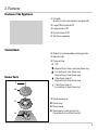
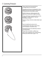
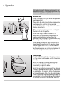
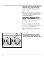
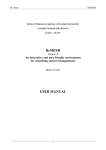
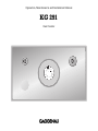
Operation, Maintenance and Installation Manual
KG 291
Gas Cooker
KG 291
1. Important Notes
For Your Safety
Operating for the First Time
About Use
2. Features
Features of the Appliance
Control Knob
Burner Parts
3. Operating Principle
4. Operation
5. Settings Table
6. Cookware Recommendations
7. Wok Cookware Recommendations
8. Cleaning and Care
9. Maintenance
10. Trouble shooting
11. Technical Data / Nozzle Table
12. Installation Instructions
Important Notes
Gas Connection / Electrical Connection
Nozzle Replacement
Installing the Appliance
Page 3-4
Page 3
Page 3
Page 4
Page 5
Page 5
Page 5
Page 5
Page 6
Page 7-8
Page 9
Page 10
Page 11
Page 12-14
Page 15
Page 16
Page 17-19
Page 20-26
Page 20-21
Page 22
Page 23-25
Page 26
1
2
1. Important Notes
For Your Safety
Operating for the First Time
You must not operate the appliance if it is damaged.
Remove the packaging from the appliance and
dispose of it according to local regulations. Be
careful to remove all accessories from the
packaging. Keep packaging elements and plastic
bags away from children.
When connecting electrical appliances in the proximity of the appliance, make sure that connecting
leads do not come into contact with hot cooking
surfaces!
As the user, you yourself are responsible for
maintenance and proper use in the household.
Check the appliance for transport damage before
installing it.
Do not operate the appliance without pots and pans
placed on it. Make sure that all the burner parts are
correctly fitted.
The appliance must be installed and connected by
an authorised specialist before operation. The
installation must conform with all current regulations
of the gas supply companies and the regional
construction regulations.
Caution: The appliance heats up during operation.
Keep children away.
Turn all control knobs to the OFF position before
connecting the appliance to the power supply.
Do not clean the appliance with a steam cleaning
apparatus or with water pressure - risk of shortcircuits!
The serial number of the appliance can be found on
the quality control slip which is included with these
instructions. This quality control slip should be kept,
for guarantee reasons, together with your operating
and assembly instructions.
Only ever operate the appliance under supervision.
Isolate the appliance from the mains during every
maintenance operation. To do this, remove the
mains plug or switch off the corresponding
household fuse. Close the gas supply.
Repairs must be carried out by authorised specialists, thus ensuring electrical safety.
No warranty claims can be lodged for any damage
resulting from failure to observe these instructions.
Read through these instructions attentively before
operating your appliance for the first time.
Thoroughly clean the appliance and accessories
before using them for the first time. This will
eliminate any 'newness' smells and soiling (see
chapter “Cleaning and care”).
Observe caution with oils and fats. They may
overheat and burn easily.
Foodstuffs that are prepared in fat and oil must only
be prepared under constant supervision!
Technical modifications reserved.
3
About Use
The appliance is intended solely for use in the
household and must not be put to any other uses.
Use the appliance to prepare meals only. It must not
be used to heat up the room in which it is installed.
Use of a gas cooker generates heat and humidity
in the room where it is installed. This is why attention must be paid to good kitchen ventilation.
The natural ventilation openings must be kept
unobstructed. Prolonged use of the appliance
with several or all rings may call for additional
ventilation such as opening a window or a door,
or stronger air extraction by an extractor hood.
To guarantee good combustion, the room in
which the appliance is installed must have
a minimum volume of 35 m3 and must possess
a door that opens outdoors or a window that
can be opened.
Keep the ventilation openings at the back of the
appliance free at all times.
Only ever use the burners after placing pots
and pans on them. Do not heat up any empty
pots or pans.
It is not permitted to use roasting pans, frying pans
or grill stones heated simultaneously by several
burners because the resulting heat build-up may
damage the appliance.
4
Pots with a diameter of less than 90 mm or more
than 280 mm / 320 mm for the large (WOK)
burner should not be used. When using large pots,
pay attention to keeping to a minimum distance of
50 mm between the cooking vessel and
combustible surroundings.
A minimum distance of 50 mm must be observed
between the control knob / control panel and the
pot or pan. The pot or pan should not touch the
control panel.
Switch the burners to the low setting whenever you
remove pots or pans briefly. In this way, you reduce
the risk of burns when working next to naked
flames; you also save gas and reduce pollution.
Whenever the gas hob is fitted under an extractor
hood, always cover the rings with pots or pans.
Otherwise, parts of the extractor hood may become
damaged by the extreme heat development or
grease residues in the filter may ignite.
Ensure an adequate supply of air when using
an extractor hood operating in the extraction
mode
The appliance cannot be used during a power
failure.
In the event of malfunctions, please inform your
specialist dealer or your nearest Gaggenau aftersales service.
2. Features
Features of the Appliance
1 Pot grids
(3 parts, the left and right part are identical)
2 Large (Wok) burner 5 kW
3 Large burner 4 kW
4 Normal burner 2 kW
5 Ventilation openings
Control Knob
6 Symbol for corresponding cooking position
7 Indicator light
8 Flame setting:
0 OFF
High setting of outer and inner flame ring
Low setting of outer flame ring
High setting of inner flame ring
Burner Parts
9
Outer flame ring off
High setting of inner flame ring
Outer flame ring off
Low setting of inner flame ring
10
9 Burner head cover
11
10 Burner ring
11 Burner head
12
12 Electrode for automatic ignition,
flame detection and flame control
5
3. Operating Principle
The gas hob features two normal burners,
two large burners and a Wok burner.
The appliance features one-hand operation, flame
detection and automatic re-ignition. The ignition is
activated when the control knob is turned.
Should the flame go out during operation, the
appliance will automatically re-ignite the burner.
During a disturbance, the appliance will cut off the
gas supply as a safety measure, to prevent
unburned gas escaping.
The flame setting is infinitely variable between high
and low.
The total rated thermal load amounts to:
17.0 kW referred to Hs* (gross calorific value)
15.3 kW referred to Hi (calorific value)
The specified rated load is defined by installation
of the fixed nozzles.
The gas hob is converted to a different gas
type by nozzle replacement (full and low-burning
nozzles) (see nozzle table on page 17-19).
6
4. Operation
Only light a burner if all burner parts are dry, and
assembled correctly. Otherwise, malfunctions may
occur or the appliance may switch off.
Switching on
• Place a suitable pot or a pan on the corresponding
cooking position.
• Press down the control knob for the corresponding
cooking position and turn it to the required
position between the and symbols. The burner
ignites automatically.
• When using large pots or pans you should ignite
the burner in the low position.
• Every time the gas hob is switched on, the
electronics run an auto test. All electrodes fire
and the required burner ignites after a few
seconds. When switching on further burners, only
the corresponding electrode fires.
• When being switched on, a short sound may be
heard when the electronic of the gas hob opens
the gas supply valve. This is a normal condition.
The flame size can be set continuously between full
and low by slowly turning the control knob.
Indicator light
The indicator light next to the control knob comes
on, if the burner is switched on and the flame burns
correctly.
Should the flame go out during operation (e.g.
because of a draught), the appliance will
automatically re-ignite the burner.
Should the re-ignition be unsuccessful (e.g. burner
is soiled by spilled over food or liquid), all burners
are switched off, the indicator lights of the burners
that were switched on flash. Turn all control knobs
to the OFF position. The flashing indicator lights will
go out except for the affected burner. This indicator
will continue to flash for a few seconds. After the
7
appliance has cooled down sufficiently, check this
burner to see if all the burner parts have been
assembled correctly. Check if the burner or the
electrode has been soiled (see trouble shooting
guide on page 16).
Note: if a malfunction occurs on one burner, you
can continue using the remaining burners, however,
you must turn all control knobs to the off-position
first, before recommencing.
Please note when switching on the cold
appliance on the HIGH setting: depending on
the gas type and pressure, it is possible that the
electrode continues to fire, although there is a
flame visible, and then switches off.
Turn all control knobs to the OFF position. Then
turn the control knob for the required cooking
position to any setting except the high position and
leave to warm up for 30 to 60 seconds.
Then you can continue to use your appliance as
usual.
Switching off
Fully turn the control knob to the OFF position.
The electronics of the appliance switch the gas
supply off, if all control knobs are in the off position.
8
5. Settings Table
Cooking
level
Cooking method
Examples
High
Boiling
Searing
Heating
Boiling
Blanching
Water
Meat
Fat, liquids
Soup, sauce
Vegetables
Roasting
Browning
Roasting
Baking
Boiling in open pot
Simmering in open pot
Meat, fish, potatoes
Flour, onions
Almonds, breadcrumbs
Pancakes, egg dishes
Liquids
Dumplings, sausages, soup garnish,
meat stock, poached eggs
Simmering
Boiling with closed lid
Steaming
Stewing
Braising
Sweet sauces
Pasta, soup, sauces
Vegetables, potatoes, fish
Vegetables, fruit, fish
Goulash, rolled beef steaks, roasts,
vegetables
Thawing
Slow cooking
Reheating
Frozen foods
Rice, pulses
Soup, casserole, vegetables in a sauce
From
to
From
to
Low
Switch to the high setting in order to reach the required temperature quickly. Then switch back to a lower
setting.
The output of the inner flame ring is the same on the normal, as well as the large burners.
The values given above must be looked upon as recommended values. The heat required depends not
only on the type and condition of the food, but also the size and contents of the pot.
Due to the high performance of the cooktop, fat and oil will heat up quickly. Never leave the cooktop
unattended, fat can ignite, food can burn.
Preferably use the rear cooking zones to prepare meals, that need longer to cook.
Preferably use the larger burners or the wok burner for brief cooking, deep fat frying and brief frying of
large quantities.
9
6. Cookware Recommendations
KG 291
Recommended
pot diameter
Normal Burner
200 - 240 mm
Large Burner
240 - 280 mm
Large Burner (Wok) 240 - 320 mm
Minimum
pot diameter
90 mm
90 mm
160 mm
Pots with a diameter of less than 90 mm or more
than 280 mm / 320 mm for the large (WOK)
burner should not be used. When using large pots,
pay attention to keeping to a minimum distance of
50 mm between the cooking vessel and
combustible surroundings.
A minimum distance of 50 mm must be observed
between the control knob / control panel and the
pot or pan. The pot or pan should not touch the
control panel.
When buying pots, pay attention to the fact
that the manufacturer frequently specifies the top
pot diameter, which is generally larger than the
diameter of the base.
Observe the manufacturer’s specifications! Use
cooking utensils that the manufacturer states as
being “suitable for gas". Use pots with heat resistant
handles.
Use pots and pans with a thick base, because heat
distribution is particularly improved in the low
setting. Using the correct size of pots and pans for
the burner ensures improved cooking performance
and energy efficiency.
To ensure an even distribution of heat, center the
pot above the burner. The flames should be
covered by the pot base.
Place the pot or pan securely and level on the pot
grid. Turn the pan handle to the side, it should not
point to the front. In order to guarantee a secure
position on the pot grid, the pot base should be flat
and not warped or dented.
Placing a fitting lid on the pot will shorten cooking
times. Through a glass lid you can watch the
cooking progress without having to take the lid off.
10
7. Wok Cookware Recommendations
The Wok and Accessories
(not included in the scope of delivery)
– The round-bottom wok is the ideal wok for your
gas cooker.
– The wok looks like a hollow semisphere with a
long handle or wooden handle. It has a rounded
base and slanted sides. The thin steel passes the
heat swiftly to the inside, but soon cools down
again as soon as the flame is set to a lower
setting. Therefore, ingredients cannot overcook.
– The diameter is between 35 - 40 cm for 4 persons.
– Make sure that a wok with a rounded base is
positioned safely on the pot grid.
– Woks may consist of various materials. Cast-iron
woks are more stable and keep the heat longer.
– They have a round, high cover. Therefore, they
are also capable of steaming and stewing.
– The semicircular grid is hooked in on the edge of
the wok. On it, you can steam ingredients, you
can allow deep fried foods to drip or you can
keep browned foods warm.
– Use the chan (rounded spatula) or a long handled,
wooden spatula.
Cooking in the Wok
You can fry, steam, deep fry, stew and cook normally.
Stir frying is the special cooking method for the
wok. Ingredients cut into small pieces are cooked
as briefly as possible under strong heat and
constant stirring. In the large, round pan everything
can be stirred and turned faster and with greater
ease than in a conventional frying pan. Thanks to
stirring, ingredients do not burn onto the pan.
Surplus oil drains off towards the middle. In next to
no time, you obtain delicious roasted foods, the
pores in meat close and fish becomes nices and
juicy. Vegetables stay crispy, and aromas and
healthy vitamins are retained.
Important: the cooking time is so short that all
ingredients should be ready for cooking before you
begin. The correct sequence is also important. First
place the ingredients with the longest cooking time
in the wok. For example, these are hard-fibred
vegetables such as carrots. Soft vegetables such as
mushrooms or sprouts are added later.
Proceed as follows:
– Pour sufficient oil into the wok to coat the surface.
We advise you to use peanut or or soya oil.
– Use a ladle to remove foods.
– Heat up the oil to just before the smoking point;
only then begin with stir frying.
– Use the strainer to lift deep fried foods from the
fat or large pieces out of a sauce.
– Cut the food into pieces of equal size, but not too
small, thus making sure they will not burn.
– You can use bamboo baskets for steaming.
– If you are cooking larger quantities, work with
portions as otherwise not all of the food will reach
the hot base of the wok.
– Meals that are ready ca be kept warm on a
minimal flame. Clean the wok after every use and
rub its inside with oil. This will prevent rusting.
11
8. Cleaning and Care
Keep the ventilation openings on the rear of the
appliance clean. Do not block the ventilation
openings.
The burners (burner head cover, burner ring and
burner head) will change their color during
operation and become darker. This change in color
will not influence the use-value.
Please thoroughly clean the appliance before
operating it for the first time and after every use.
12
Do not use scouring agents, abrasives or chemically
aggressive cleaners (for example oven cleaner)!
Do not use any nitro polishing agents for cleaning!
Do not use any abrasive sponges either.
Before cleaning, please wait until the cooktop
has cooled to hand-warm.
• First lift one of the pot grids on the side with both
hands (be careful not to scratch the base). Then
remove the remaining two pot grids.
• Remove the burner head cover, the burner ring
and the burner head.
• Important! Only clean the burner parts when
cold!
• Soak burnt-in remainders in a little water and
detergent. This loosens even the most stubborn of
soiling. Do not use any abrasive agents and
abrasive sponges.
• Only use very little water to clean your cooktop.
Be careful that no water enters the burner base.
• As the result of heat development, slight discoloration can appear on the stainless steel
surface. Do not attempt to scrape away such
discoloration. This damages the surface.
Distribute stainless steel care agents uniformly
and thinly on the hob (not on the control panel!).
This will ensure an even surface and will keep
your hob in a good condition for a long period of
time.
• Make sure the burner parts are dry before
assembly. Only operate the appliance with all
parts dry. Damp burner parts will cause
malfunctions when igniting or unstable flames.
• When assembling the burner parts, make sure
that the burner ring and burner head are placed in
such a way that the locking lugs fit in the
corresponding recesses.
• Important! Fit the middle pot support first
(be careful to center it over the burner) and
then the pot supports on the side. The
rounded corners of the pot supports on the
side must face out to the side.
Part / Material
Suggested Cleaning Procedure
Important Reminders
Control Panel
(anodized
aluminum)
Use cloth with detergent and hot water.
Remove greasy splashes with a
commercially available cleaner for
aluminum. Make sure the cleaning
agent will not scratch the surface.
Do not use strongly alkaline cleaning
agents. These cleaners may cause
permanent discoloration!
Control Knobs
(mat chromium
plated )
Use cloth with detergent and hot water.
Do not clean in a dishwasher.
see next page
13
Part / Material
Suggested Cleaning Procedure
Important Reminders
Pot Grid
(enamel on
cast iron)
Take pot grids off for cleaning.
Soak in sink. Clean with detergent
and brush.
Do not clean in a dishwasher.
Soak burnt-in remainders in sink.
Abrasive cleaners, used too vigorously or
too often can eventually mar the enamel.
Burner Head Cover,
Burner Ring,
Burner Head
(brass)
Remove coarse soiling with damp
cloth and detergent.
Use brass polish to keep the
original shiny surface.
Do not clean in a dishwasher.
Port openings must be kept free.
Be careful not to loose the small parts.
Wok Burner Head
(enamel on
cast iron)
Clean with detergent and brush.
Do not clean in a dishwasher.
Electrode
Clean with brush, fine glass-paper
or scouring pad.
Soiled electrodes may cause malfunctions
when igniting or flame control disturbance.
Be careful when cleaning electrodes,
they are fragile, do not turn.
Caution: never switch on cooktop while
cleaning electrodes.
Base
(stainless steel,
shot blasted,
brushed)
Cloth with detergent and hot water.
Soak burnt-in remainders with a
little detergent solution.
After cleaning, polish dry with a
soft cloth to prevent water stains
forming on the surface.
For heavy soiling, you can order
our stainless steel cleaner (Order
No. 310631) from your Gaggenau
dealer.
Caution: no liquid should enter
the housing of the cooktop
through the burner base.
To prevent marring the polished stainless
steel trough, always polish in the direction
of the polish lines.
Light discolorations may form if the
natural oxidation is removed together
with the soiling. Put some commercially
available stainless steel polish on a cloth
and polish the whole cooktop after cleaning
to get an even stainless steel surface.
Never allow food stains or salt to remain
on stainless steel for any length of time.
Important: certain stainless steel cleaners
will scratch the surface. Chlorine or
chlorine compounds in some cleaners are
corrosive to stainless steel. Check
ingredients on label.
14
9. Maintenance
The appliance must be disconnected from the
power and gas supply during all repair work.
In the event of malfunctions, check whether the gas
and electricity supplies are in proper working
order.
The cooktop cannot be used during a power failure.
If the cooktop is being used when the power failure
occurs, turn all of the burner control knobs to the
OFF position. The cooktop will not turn back on
after a power failure until all control knobs are first
turned OFF and then turned back on again.
Before calling the service engineer, check the
trouble-shooting guide on page 16 to see, if you can
rectify the problem yourself. If your appliance still
does not work, please contact your dealer or your
local Gaggenau customer service agency. Specify
the appliance type (see rating plate).
Repairs may only be carried out by authorised
technicians, in order to guarantee the safety of the
appliance.
Unauthorised tampering with the appliance will
invalidate any warranty claims.
Only use original spare parts.
15
10. Trouble shooting
Burner does not ignite when switched on
Indicator lights
are off
No electrical
power
Turn control
knob to 0
Burners go off during operation
Indicator light of
the switched on
burner is flashing
Turn control
knob to 0
• Are all burner
parts correctly
assembled?
• Check the
domestic fuse
• Is the gas shutoff valve open?
• Is the appliance
plugged in?
• Is the burner
dry and clean?
• Is there an air
pocket in the
gas supply line
after first installation or
changing the LP
(propane) gas
tank?
• LP (propane)
gas: is the gas
tank empty?
Turn all control knobs to 0
Indicator lights go off, only
the indicator light of the
affected burner continues to
flash for a few seconds
Wait, until the appliance
has cooled.
Check affected burner:
• Are all burner parts
correctly assembled?
Indicator lights
go off
All indicator
lights are flashing
After a power cut, the
appliance does not re-ignite
automatically
Overheating
protection
Check the power supply
Wait, until
indicator lights
go off
• Is the electrode soiled
(food remains) or wet?
• Is the burner soiled by
boiled over food?
• Check for strong draughts
(for example open window
behind the cooktop)?
• LP (propane) gas: is the
gas tank empty?
Switch the appliance on again. Should the appliance still not work, contact your Gaggenau after-sales service.
16
11. Technical Data / Nozzle Table
Technical data (gas)
Burners:
Gas connection: R 1/2’’ union nut for R 1/2’’
bracket to DIN 1999, conical-cylindrical
Normal burner
Full burning
Low burning
Large burner
Full burning
Low burning
Wok burner
Full burning
Low burning
Total output
2.0 kW
0.165 kW
4.0 kW
0.165 kW
5.0 kW
0.3 kW
17.0 kW
Technical data (electrical)
Rated consumption
15 W
Voltage
AC 220-240 V
Frequency
50-60 Hz
Technical modifications reserved.
Nozzle table wok burner
Countries
AT BE CH CZ
DE DK ES FI
FR GB GR HU
IE IS IT LU NL
PL PT RU SE
DE
BE CH CZ DK
ES FI FR GB
GR HU IE IS
IT LU NO PL
PT RU
AT CH DE
Gas family
Natural gas
Natural gas
LPG/Propane
LPG/Prop.
Gas type
H / E / L (G 20/25)
LL (G 25)
3 + (G30/31)
(G30/31)
Pressure
20/25 mbar
20 mbar
28-30/37 mbar
50 mbar
Nozzle, full burn, outer
1.55
1.70 B
1.00
0.87
Nozzle, low burn, outer
0.73
0.81
0.51
0.45
Nozzle, full burn, inner
0.58
0.63
0.37
0.33
Nozzle, low burn, inner
0.45
0.51
0.31
0.25
Air gap adjustm. outer [mm]
0
0
2
0
Air gap adjustm. inner [mm]
*
*
*
*
Total output
17 kW
17 kW
17 kW
1240 g/h
1240 g/h
Total consumption
1.70
m3/h
17 kW
1.87
m3/h
* open, fixed
17
Nozzle table normal burner
Countries
AT BE CH CZ
DE DK ES FI
FR GB GR HU
IE IS IT LU NL
PL PT RU SE
DE
BE CH CZ DK
ES FI FR GB
GR HU IE IS
IT LU NO PL
PT RU
AT CH DE
Gas family
Natural gas
Natural gas
LPG/Propane
LPG/Prop.
Gas type
H / E / L (G 20/25)
LL (G 25)
3 + (G30/31)
(G30/31)
Pressure
20/25 mbar
20 mbar
28-30/37 mbar
50 mbar
Nozzle, full burn, outer
0.98
1.05
0.64
0.57
Nozzle, low burn, outer
0.48
0.51
0.29
0.26
Nozzle, full burn, inner
0.40
0.42
0.26
0.22
Nozzle, low burn, inner
0.36
0.40
0.22
0.21
Air gap adjustm. outer [mm]
0
0
6 (max)
6 (max)
Air gap adjustm. inner [mm]
*
*
*
*
Total output
17 kW
17 kW
17 kW
1240 g/h
1240 g/h
Total consumption
* open, fixed
18
1.70
m3/h
17 kW
1.87
m3/h
Nozzle table large burner
Countries
AT BE CH CZ
DE DK ES FI
FR GB GR HU
IE IS IT LU NL
PL PT RU SE
DE
BE CH CZ DK
ES FI FR GB
GR HU IE IS
IT LU NO PL
PT RU
AT CH DE
Gas family
Natural gas
Natural gas
LPG/Propane
LPG/Prop.
Gas type
H / E / L (G 20/25)
LL (G 25)
3 + (G30/31)
(G30/31)
Pressure
20/25 mbar
20 mbar
28-30/37 mbar
50 mbar
Nozzle, full burn, outer
1.37
1.55
0.94
0.82
Nozzle, low burn, outer
0.59
0.65
0.40
0.35
Nozzle, full burn, inner
0.40
0.42
0.26
0.22
Nozzle, low burn, inner
0.36
0.40
0.22
0.21
Air gap adjustm. outer [mm]
0
0
0
0
Air gap adjustm. inner [mm]
*
*
*
*
Total output
17 kW
17 kW
17 kW
17 kW
Total consumption
1.70 m3/h
1.87 m3/h
1240 g/h
1240 g/h
* open, fixed
19
12. Installation Instructions
Important Notes
Please observe the general safety notes and the
important information in chapter 1.
The installing technician is responsible for
perfect functioning of the appliance at its installation location.
He must show the user how to switch off the
electricity and gas supply whenever required.
As this gas hob is not intended for connection to an
exhaust gas system, pay attention to the applicable
installation conditions.
The appliance may be installed in kitchen
combinations made of wood or similar combustible
materials without taking additional measures. The
rear wall must consist of non-combustible material.
After unpacking, check the appliance for any
transportation damage and report this immediately
to the transportation company.
A minimum distance of 300 mm from heat-sensitive
items of furnishing or contact surfaces (cupboard
side panel) must be observed.
Caution:
before connecting the appliance, please check
whether the local connection conditions such
as gas type, gas pressure and mains voltage
match the appliance settings. This gas hob
conforms to the categories that are specified on the
rating plate. The rating plate can be found on the
appliance and additionally on the quality control
slip which is included with these instructions. By
replacing nozzles, it is possible to set the appliance
to any gas listed on the rating plate.
If the data should not match, the appliance must
be changed over to the required gas type and the
available pressure.
The hob conforms to appliance class 3 and must be
installed in the worktop as shown in the installation
sketch.
Do not install the appliance under a suspended
cupboard. For installation under a vapour extractor,
a minimum clearance of 760 mm must be
observed. Wall trims must be heat-resistant, and the
minimum distance between the hob and the wall
trim is at least 30 mm.
The appliance must be installed and connected by
an authorised gas installer. The installation must
conform with all current regulations of the gas
supply companies and the regional construction
regulations.
Technical modifications reserved.
20
Note on ventilation:
this household gas cooker has a total rated thermal
load of 17 kW (Hs).
Simultaneous use of all cooking positions of the
cooker generates heat and humidity in the room
where it is installed. This is why attention must be
paid to good kitchen ventilation.
This can be guaranteed for example by installing
an extractor hood with a minimum air output of
264 m3/h (= 15 m3/h per kW thermal load).
To ensure ventilation, the room in which this
appliance is installed must have a suitable opening,
like an exterior door or a window that can be
opened.
When using the household gas cooker, the extractor
hood must be operated in such a way, that, the
more cooking positions are used, the higher the air
output level must be.
21
Connecting the appliance
50
max.
105
28
1/2"
Electrical connection
Electrical connection (AC 220-240 V) is established
by means of a connecting cable with an earthing
contact plug connected to an earthed socket, which
must also be accessible after installation of the gas
hob.
If, after installation of the gas hob, not all poles can
be isolated from the mains by removing the plug,
an isolating device with a contact gap of at least
3 mm must be permanently installed. When establishing connections, make sure that the connecting
lead cannot come into contact with hot parts of the
gas hob or other hot parts.
Turn all control knobs to the OFF position before
connecting the appliance to the power supply.
22
Gas connection
The gas connection must be in a location that
permits access to the shut-off valve and which,
if applicable, is visible after opening the door of
the cabinet.
By means of the included R 1/2“ connection bracket
(on the appliance end) with the affiliated washer,
the appliance must be connected to a fixed connecting line or a gas safety hose to DIN 3383
Part 1 that corresponds to the type concerned.
An ambient temperature of 70 °K must not be
exceeded if the gas safety hose consists only partly
of metal. The permissible ambient temperature for
a gas safety hose that consists completely of metal
is 115 °K.
If a flexible line is used, it must be laid in such a
way that it cannot come into contact with moving
parts of the kitchen element (e.g. drawer).
The mains connecting cable must at least
correspond to type H 05 V2V2 3G 0.75 or it must be
correspondingly heat-resistant (at least 90 °C).
The mains connecting cable must only be
purchased through and connected by an
authorised specialist.
Pay attention to the information on the rating plate
and connect the PE conductor. Connect the
connecting cable to the mains.
Connection type Y: if damaged, the mains cable
must be replaced by a special mains connecting
cable. The mains connecting cable must only be
connected by the manufacturer or the manufacturer's after-sales service.
Nozzle Replacement
Changing over to a different gas type
Only authorised specialists are permitted to
change over to a different gas type.
The nozzles needed for the gas type to be set
are available as a conversion kit. Please specify the
appliance type and the required gas type. The
nozzles can be changed on the installed appliance.
outer low
setting nozzle
inner low
setting
nozzle
Loads for all gases
For all gas types and pressures, the rated load
is achieved by installing the high and low setting
nozzles for the required gas type (see nozzle
table).
Replacing the low setting nozzles
• Switch off the power at fuse point and close the
gas supply!
• Detach pod grids, burner rings, burner head
covers and burner heads.
See table on page 17-19
for details of nozzle settings.
• Pull off control knobs. Undo trough securing nuts
(three 7 mm nuts on each burner) and carefully
detach the trough.
• Turn the black plastic part so that the recess is
above the nozzle. Screw out nozzle and take
nozzle out with small pliers.
• Replace both low setting nozzles on the gas taps
according to the new gas type and as detailed in
the low setting nozzle table. Fully screw in the
new low setting nozzles.
Important: be careful not to damage the O-ring.
23
inner main nozzle
Replacing the main burner nozzles of the
normal burner and large burner
• Detach the safety spring on the supply lines.
Leave the electrode connected. Unscrew the
burners from the trough (Torx T20) and pull off the
burner from both supply lines.
• Carefully pull off both main nozzles together with
the O-ring by hand.
outer main nozzle
See table on page 17-19
for details of nozzle settings.
• Check whether the O-rings of the new nozzle
seats are fitted correctly. Fully push nozzles onto
the supply lines. Note: do not bend supply lines.
• Push the burners onto the supply lines.
Push the safety springs back on.
• Screw the burners back on the trough.
• Loosen the locking screw and adjust the air
regulation bush according to the nozzle table.
Tighten the locking screw.
24
outer main nozzle
inner main
nozzle
See table on page 17-19
for details of nozzle settings.
Replacing the main burner nozzles of the
wok-burner
• Unscrew the Wok burner from the trough
(Torx T20). Loosen locking screw from the air
regulation bush. Fully push in the air regulation
bush. Detach the safety springs on the supply line.
Leave the electrode connected.
• Carefully pull off the Wok burner from both supply
lines. Carefully pull off the inner main nozzle with
O-ring by hand. Screw out the outer main nozzle
(10 mm).
• Check whether the O-ring is fitted correctly in the
nozzle seat of the new inner main nozzle. Fully
push nozzle onto the supply lines. Note: do not
bend supply lines.
• Change the screw-in nozzle and tighten it firmly.
• Push the burners onto the supply lines.
Push the safety springs back on.
• Screw the burner back on the trough.
• Loosen the locking screw and adjust the air
regulation bush according to the nozzle table.
Tighten the locking screw.
• Fit the trough and tighten it firmly.
Checking functions
The flames are adjusted correctly if no yellow tips
are visible and if they do not go out when switching
over swiftly from the high to the low setting.
Please do not forget to stick the new adhesive label
included with the nozzle set over the old adhesive
label on the gas connection, thus documenting the
changeover to a different gas type.
25
Installing the Appliance
914
8,5*
gs
n openin
nd
veentnilahtio
litzen
6,5
6,5aat
*1*1
saugsc
Luftan
510
Note: the appliance can be installed in a base
cabinet with a minimum width of 900 mm. The
recess in the countertop will be slightly wider than
the inner width of the base cabinet.
Do not install the appliance above a drawer.
min.
30
• Produce the recess for the cooktop in your
countertop. Proceed as indicated on the
installation sketch.
Note: the angle between the cut surface and the
worktop must be 90°.
130
1,4 m
176,5
5
min. 3
442,5
490
0
min. 5
885
• Turn the clamping screws to the side. Insert the
hob with the control panel on the front into the cutout.
• Align the cooktop and turn the clamping screws
under the countertop. Tighten the clamping
screws evenly.
• Connect the appliance to the gas supply.
Note: if a flexible gas connection is being used,
you can connect the appliance before installing it
into the worktop.
• Check the installation for gas leaks.
• Connect the appliance to the electricity. Test it for
correct functioning.
• There might be an air pocket in the gas supply line
if the appliance switches off and the indicator
lights flash. Turn all control knobs off and switch
on again (see trouble-shooting guide, chapter 10).
26
5080008618ind01
en 07.04 EB
GAGGENAU HAUSGERÄTE GMBH
CARL-WERY-STR. 34 · D - 81739 MÜNCHEN
Y (0 89) 45 90 - 03
FAX (0 89) 45 90 - 23 47
www.gaggenau.com
31