1
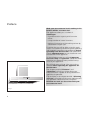
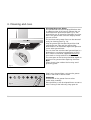
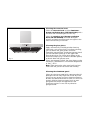
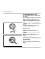
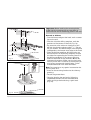
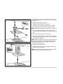
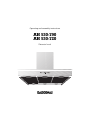
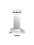
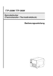
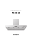
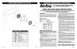
AH 530-790
AH 530-720
Preface
Safety notes
1. Important notes
1.1 For your safety
1.2 Operating for the first time
1.3 About use
2. Features
3. Operation
4. Cleaning and care
5. Maintenance
6. Assembly instructions
6.1 Technical data
6.2 Installation
Page 3
Page 4-5
Page 4
Page 5
Page 5
Page 6
Page 7-9
Page 10-11
Page 12
Page13-17
Page 13
Page 14-17
1
Preface
With your new extractor hood, working in the
kitchen will be even more fun.
The appliance offers you a number of
advantages:
– A good extraction capacity with low noise
values,
– a large number of control functions,
– optimum illumination of the cooking surface by
a dimmable halogen light.
To ensure that you will be able to use this appliance in all its diversity, read through the operating
and assembly instructions conscientiously before
operating it for the first time. The instructions
contain important notes on use, installation and
maintenance of the appliance.
On the following page you will find important
notes on safety and operation. These will serve
to ensure your personal safety and the lasting
value of your appliance.
You will find notes on Page 4 that you ought to
observe before operating the appliance for
the first time.
The chapters entitled “Features” and
“Operation” will tell you all the things your
extractor hood is capable of doing and how the
appliance is operated.
Tips and hints in the chapter entitled “Cleaning
and care” will make sure that your appliance will
stay operable and beautiful for a long time.
And now we wish you lots of fun with your
new extractor hood.
Fig. 1
2
Safety notes
Read And Save These Instructions.
WARNING - TO REDUCE THE RISK OF FIRE,
ELECTRIC SHOCK, OR INJURY TO PERSONS,
OBSERVE THE FOLLOWING:
a.) Use this unit only in the manner intended by the
manufacturer. If you have questions, contact
the manufacturer.
b.) Before servicing or cleaning unit, switch power
off at service panel and lock the service
disconnecting means to prevent power from
being switched on accidentally. When the
service disconnecting means cannot be locked,
securely fasten a prominent warning device,
such as a tag, to the service panel.
WARNING - TO REDUCE THE RISK OF INJURY
TO PERSONS IN THE EVENT OF A RANGE
TOP GREASE FIRE, OBSERVE THE
FOLLOWING:
a.) SMOTHER FLAMES with a close-fitting lid,
cookie sheet, or metal tray, then turn off the
burner. BE CAREFUL TO PREVENT BURNS. If the
flames do not go out immediately, EVACUATE
AND CALL THE FIRE DEPARTMENT.
b.) NEVER PICK UP A FLAMING PAN - You may be
burned.
c.) DO NOT USE WATER, including wet dishcloth or
towels - a violent steam explosion will result.
d.) Use an extinguisher ONLY if:
CAUTION:
FOR GENERAL VENTILATION USE ONLY. DO NOT
USE TO EXHAUST HAZARDOUS OR EXPLOSIVE
MATERIALS AND VAPORS.
1. You know you have Class ABC extinguisher,
and you already know how to operate it.
2. The fire is small and contained in the area
where it started.
3. The fire department is being called.
WARNING - TO REDUCE THE RISK OF A
RANGE TOP GREASE FIRE.
4. You can fight the fire with your back to an exit.
a.) Never leave surface units unattended at high
settings. Boilovers cause smoking and greasy
spillovers that may ignite. Heat oils slowly on low
or medium settings.
b.) Always turn hood ON when cooking at high heat
or when cooking flaming foods.
c.) Clean ventilating fans frequently. Grease should
not be allowed to accumulate on fan or filter.
d.) Use proper pan size. Always use cookware
appropriate for the size of the surface element.
3
1. Important notes
1.1 For your safety
– Damaged appliances must not be operated.
– The appliance must only be connected by an
authorised specialist, paying attention to
the relevant regulations of the power supply
companies and the regional construction
regulations.
Also observe the assembly instructions!
– Connecting cables must not come into contact
with hot cooking surfaces.
– Do not operate the extractor hood without
inserted lamps.
– Never operate the appliance without a grease
filter.
– Hazardous or explosive substances and vapours
must not be extracted!
– The user is responsible for expert use and the
perfect condition of the appliance.
– Only ever operate the appliance under supervision.
– Caution! Over-greased filters are a fire risk!
Only ever deep-fry under the extractor under
constant supervision. Pay attention to cleaning
the grease filter on a regular basis.
– Fire risk! Do not flambé meals under the
extractor hood!
– Operation of the extractor hood above a hearth
for solid fuels (coal or wood etc.) is only partly
permitted.
– Gas appliances may only be used under the
extractor hood when pots and pans are placed
on them!
– When using more than 3 gas-operated rings at
the same time, please operate the extractor
hood at level 2 or higher. This prevents a buildup of heat in the appliance.
– For safety reasons, do not place any heavy
objects on the top of the appliance.
– Do not clean the appliance with a steam
cleaning apparatus or with water pressure
because this poses a risk of short-circuits.
4
– Isolate the appliance from the mains during
every maintenance operation. To do this, actuate
the corresponding fuse.
– Repairs must be carried out by authorised
specialists, thus ensuring electrical safety.
– No warranty claims can be lodged in the event
of damage caused by failure to observe these
instructions.
– Adequate incoming air must be ensured if a
wood, coal, gas or oil heater or an open hearth is
operated in the same room as the one in which
the hood is installed.
– Safe operation is possible whenever the partial
vacuum in the place where the firing equipment
is installed does not exceed 4 Pa (0.04 mbar).
This can be achieved whenever the air needed
for combustion is able to enter through openings
that cannot be sealed, for example in doors,
windows, incoming/exhaust air wall boxes or
other technical means.
– If the appliance is to be operated only with the
window open (to ensure adequate incoming air),
you can use the window switch.
A switch (normally open) is fitted on the window.
On the appliance, this switch is connected to the
window switch terminal on the main electronics.
The appliance can now only be operated when
the window is open.
Important: The window switch must only be
connected by an authorised specialist.
Note: The light function works without restriction.
– After a power failure, the extactor will not go on
again automatically. You can recommence
operation by turning a knob or by pressing any
key.
Technical modifications reserved.
1.2 Operating for the first time
1.3 About use
Before operating the appliance for the first time,
please pay attention to the following notes:
– The appliance is intended solely for use in the
household and must not be put to any other uses.
– The appliance must be installed and connected
by a specialist before it is operated for the first
time.
– In the event of malfunctions, first of all check the
household fuses. If the problem has nothing to
do with the power supply, please contact your
specialist dealer or your local Gaggenau aftersales service.
– The rating plate for this appliance is included
with the instructions on a separate sheet. Store
the rating plate in the same location as your
operating and assembly instructions. You need
the rating plate for possible damage and
warranty cases.
– Conscientiously read through the operating and
assembly instructions before operating the
appliance for the first time.
– Remove the packaging from the appliance and
dispose of it properly. Pay attention to the fact
that there are accessories in the packaging.
Keep packaging elements out of the reach of
children!
– Thoroughly clean the appliance before using it
for the first time (see chapter entitled “Cleaning
and care”).
– Before operating the appliance for the first time,
check that the mains connection is in proper
working order.
5
2. Features
1 Outgoing air duct
2 Control panel
3 Grease filter
4 Lighting
1
2
3
4
Fig. 2
Installation accessories:
Grease filter
saturation display
Lighting
Run-on
Extraction level intensive
Extraction level 3
Extraction level 2
Extraction level 1
Motor off
Fig. 3
6
Stainless steel-design ventilation duct:
LK 530-010 for ceiling heights of
7 ´ 3 ´ ´ - 8 ´ 6 ´ ´ / 2.20 - 2.66 m
LK 530-020 for ceiling heights of
8 ´ 6 ´ ´ - 10 ´ 1 ´ ´ / 2.66 - 3.15 m
Aluminium-design ventilation duct:
LK 530-011 for ceiling heights of
7 ´ 3 ´ ´ - 8 ´ 6 ´ ´ / 2.20 - 2.66 m
LK 530-021 for ceiling heights of
8 ´ 6 ´ ´ - 10 ´ 1 ´ ´ / 2.66 - 3.15 m
3. Operation
The AH 530-790 is 35 3/8 ´ ´ / 90 cm wide, and the
AH 530-720 is 47 3/16 ´ ´ / 120 cm wide. Operation of
both extractor hoods is identical.
After they have been pressed, all functions
selection keys except 0 (“Motor off”) are backlit in
green.
Light
The lighting can be switched on or off, regardless
of whether the wall extractor is in operation, by
pressing the
key (see Fig. 4).
When you briefly press the
key, the lighting is
increased up to the maximum level.
You can dim the lighting to the required level by
keeping the
key pressed.
Fig. 4
Fan levels
Three fan speeds and one intensive speed are
available (see Fig. 5). You set the fan level required
for each respective cooking situation by pressing
the function selector keys 1, 2, 3 or Int.
or
or
or
Fig. 5
7
The Int key for the intensive level should be
pressed when browning and frying in an open pan
(see Fig. 6).
If you have switched on the hood by selecting the
intensive level, it will be switched off again
automatically after 5 minutes.
Fig. 6
If you press the Int key while the hood is running at
fan level 1, 2 or 3, the electronic control will switch
back automatically to the previously selected fan
level after 5 minutes (see Fig. 7).
Fig. 7
If you would like to end the intensive level before
the five minutes have elapsed, press the 0 key
(“Motor off”) or select a different level (see Fig. 8).
You can of course switch off the hood’s extraction
function at any time by pressing the 0 key (“Motor
off”).
Fig.. 8
8
Special functions:
or
Intensive time:
You can set the intensive level running time to 3, 5
or 10 minutes by simultaneously pressing the Int
key and the 1, 2 or 3 key and you can store this
setting (see Fig. 9). When delivered, the appliance
is set to five minutes, i.e. the combination of the Int
key and the key 2.
or
Fig. 9
Delayed shut-off:
Delayed shut-off is possible at any level. First press
the required key 1, 2, 3 or Int and then press the
key (see Fig. 10).
The delayed shut-off time for all levels is ten
minutes. After these ten minutes, the ventilation
switches off, but the lighting stays on.
or
or
or
Fig. 10
Fig. 11
or
or
Interval ventilation:
Interval ventilation is a special feature of this
appliance which periodically activates the fan for
five minutes every hour. You can activate this
function by simultaneously pressing the 0 key and,
depending on the required extraction capacity, the
1, 2 or 3 key (see Fig. 11).
This mode of operation is indicated by alternating
illumination of the
key together with the
corresponding fan level indicator.
You can switch off interval ventilation by pressing
the 0 key (see Fig. 12).
Fig. 12
9
4. Cleaning and care
Cleaning the grease filters
The grease filter saturation display F flashes after
an operating time of 30 hours to indicate that you
should clean the grease filter (see Fig. 3). The
grease filter can of course be cleaned at any time,
even if the grease filter saturation display should
not start to flash.
The stainless steel grease filters can be removed
easily for cleaning (see Fig. 13):
Grip the grease filter handle and push the slide
towards the rear. Then pull the grease filter
downwards out of the holder; repeat the operation
for the other grease filters.
You can clean the stainless steel grease filters in a
dishwasher at a maximum temperature of 150 °F /
65 °C, where it should be supported vertically to
allow food or rinsing residues to drain off.
The inner parts of the housing should be wiped out
with hot rinsing water when replacing the filters.
Note:
When cleaning the inside of the housing avoid
protruding parts.
Fig. 13
After having cleaned them, re-insert the grease
filters in the hood in reverse order.
Important:
The handles of the grease filters must be
visible after assembly.
Fig. 14
10
Press the F key to set the elapsed hours counter to
zero. Flashing of the indicating lamp goes off.
Cleaning the extractor hood
Clean the extractor hood and the aluminiumdesign ventilation ducts (LK 530-011/021) with a
soft cloth and mild detergent solution only.
Clean the stainless-steel design ventilation
ducts (LK 530-010/020) with mild detergent
solution and apply stainless steel care agent to the
metal surface using a soft cloth.
Cleaning the glass plates
Fig. 15
Apply commercially available window cleaning
agent with a soft, moist cloth. To facilitate cleaning,
you can detach the glass plates as follows:
Detach the grease filters. Inside the extractor hood,
you will find three openings on the upper side
through which you can lift the glass plates singly
with a blunt object (e.g. handle of a wooden spoon)
to detach them with greater ease.
If they are extremely soiled, the glass plates can be
cleaned in a dishwasher at a maximum temperature
of 130 °F / 55 °C.
Note: When putting the glass trays back in place,
make sure that you do not scratch the chimney.
Cleaning the aluminium panel
Clean the aluminium panel with a sponge and mild
detergent solution only. Wipe with a soft, dry cloth.
Do not use any strong or caustic cleaning agents or
brushes and abrasive cleaner to clean it. Do not use
strongly alkaline cleaning agents (such as oven
spray) because these are aggressive to the
aluminium surface. Do not use any abrasive
sponges either.
11
5. Maintenance
The appliance must be disconnected from the
power supply during all repair work.
If the appliance does not function correctly, check
the fuses first.
If the power supply is functioning correctly, but your
appliance still does not work, please contact your
Gaggenau dealer who will provide you with the
address and telephone number of your nearest
manufacturer’s authorized service agent or contact
Gaggenau USA on (800) 828-9165. Specify the
appliance type (see rating plate).
Repairs may only be carried out by authorised
technicians, in order to guarantee the safety of the
appliance.
Unauthorised tampering with the appliance will
invalidate any warranty claims.
Only ever use original spare parts.
Lamp replacement
Caution: Disconnect the power supply before
replacing lamps (switch off the fuse)!
Fig. 16
Caution: Lamps may still be hot shortly after use!
Risk of burns.
– Detach the ring from the lamp cover.
Note: Make sure that the glass will not fall out
(Fig. 16).
– Pull out the lamp (Fig. 17).
Defective lamps must only be replaced by lamps of
the same type! (12 V/20 W/G4 lampholder)
Inserting the lamp
– Insert the lamp in the lampholder.
Note: Do not touch the halogen lamps with your
hands. Use a cloth and touch the lamp only on its
edges.
– Engage the lamp cover.
– Connect the appliance to the mains again.
Fig. 17
12
6. Assembly instructions
6.1 Technical data
AH 530-790:
Weight:
23.5 kg
Dimensions: 35 3/8 ´ ´ x 20 10/16 ´ ´
898 x 550 mm
AH 530-720:
Weight:
27.5 kg
Dimensions: 47 3/16 ´ ´ x 20 10/16 ´ ´
1198 x 550 mm
Electrical connection
Pay attention to the rating plate data.
The appliance must only be connected by an
authorised specialist. The specialist is responsible for perfect functioning of the appliance at its
installation location. He must explain the operating
principle of the appliance to the user with reference to the operating instructions. He must explain
to the user how the appliance can be isolated from
the mains whenever required.
Connection possibilities
It must be possible to isolate all poles of the
appliance from the mains by way of the domestic
fuse, or by means of accessible isolating device
with a contact gap of at least 3 mm.
13
6.2 Installation
WARNING - TO REDUCE THE RISK OF FIRE,
ELECTRIC SHOCK, OR INJURY TO PERSONS,
OBSERVE THE FOLLOWING:
The applicable regulations of the energy supply
companies and the regional construction
regulations must be observed when installing
the hood.
a.) Installation work and electrical wiring must be
done by qualified person(s) in accordance with
all applicable codes and standards, including
fire-rated construction.
The minimum distance from the worktop to the
bottom edge of the wall hood is for electrical
appliances 24 ´ ´ / 600 mm and for gas appliances
27 1/2 ´ ´ / 700 mm.
b.) Sufficient air is needed for proper combustion
end exhausting of gases through the flue
(chimney) of fuel burning equipment to prevent
back drafting. Follow the heating equipment
manufacturer’s guideline and safety standards
such as those published by the National Fire
Protection Association (NFPA), and the American
Society for Heating, Refrigeration and Air
Conditioning (ASHRAE), and the local code
authorities.
The wall hood was conceived for the exhaust air
mode. The exhaust air can be routed into a
separate exhaust air shaft or directly into the open
through the outside wall.
c.) When cutting or drilling into wall or ceiling, do
not damage electrical wiring and other hidden
utilities.
During the course of planning, a chimney sweep
must be consulted if a room air-dependent hearth
is operated in the same room as the one in which a
hood is operated in the exhaust air mode. Adequate
incoming air must be ensured. The applicable
construction and safety regulations must be
observed.
d.) Ducted fans must always be vented to the
outdoors.
e.) If this unit is to be installed over a tub or shower,
it must be marked as appropriate for the application and be connected to a GFCI (Ground
Fault Circuit Interrupter) - protected branch
circuit.
f.) NEVER place a switch where it can be reached
from a tub or shower.
WARNING:
To reduce the risk of fire, use only metal ductwork.
14
It is not allowed to pass the exhaust air into a flue
or exhaust air chimney that is in operation or into a
shaft that is linked to the heating basement. Consult
the chimney sweep responsible for your district
whenever you wish to pass the exhaust air into a
chimney that is not in operation.
Adequate incoming air must be ensured if a wood,
coal, gas or oil heater or an open hearth is operated
in the same room as the one in which the hood is
installed.
Safe operation is possible whenever the partial
vacuum in the place where the firing equipment
is installed does not exceed 4 Pa (0.04 mbar).
This can be achieved whenever the air needed for
combustion is able to enter through openings that
cannot be sealed, for example in doors, windows,
incoming/exhaust air wall boxes or other technical
means.
As standard, the blow-out opening of the wall hood
is in the upward direction.
To pass exhaust air through the outer wall, we
recommend the use of our telescopic wall box
TM 150-045 (Ø 6 ´ ´ / 150 mm).
Note:
To prevent the ingress of water, e.g. condensate or
rain water from an uncovered exhaust air shaft, our
condensate separator RV 060-150 must be installed
in the exhaust air line. The condensate separator
must still be acciessible after installation.
260
(101/4”)
550
(2110/16”)
2,20 - 3,15 (7’3” - 10’1”) Ceiling height
– there are no cross-sectional constrictions in the
upward direction (this reduces the volume flow).
600-1550 (24”-5’1”) Hood height
– the pipes are not laid at an acute angle, but as
bends and that they are inserted into the shaft at
an inclined upward angle and
Stainless steel-design ventilation duct:
LK 530-010 for ceiling heights of
7 ´ 3 ´ ´ - 8 ´ 6 ´ ´ / 2.20 - 2.66 m
LK 530-020 for ceiling heights of
8 ´ 6 ´ ´ - 10 ´ 1 ´ ´ / 2.66 - 3.15 m
Aluminium-design ventilation duct:
LK 530-011 for ceiling heights of
7 ´ 3 ´ ´ - 8 ´ 6 ´ ´ / 2.20 - 2.66 m
LK 530-021 for ceiling heights of
8 ´ 6 ´ ´ - 10 ´ 1 ´ ´ / 2.66 - 3.15 m
The dimensions above refer to a distance of 5 ´ 3 ´ ´ /
1.60 m from the floor to the bottom edge of the
hood.
If required, individually sized ventilation ducts are
available at an extra charge.
The power connection must be placed behind the
duct cover on the wall.
1600 (5’3”)
Pay particular attention to ensuring that
– the exhaust air ducts and pipes are kept as short
as possible
The duct units listed below are available
depending on the height of the ceiling:
min. 600 (24”)
over electric cooker 100
480
min. 700 (271/2”)
(315/16”) (187/8”)
over gas cooker
Flexible aluminium pipes, corrosion-protected
sheet metal pipes and exhaust air pipes whose
material conforms to fire B1 in accordance with
DIN 4102 can be used. Exhaust air pipes should
have a nominal diameter of 6 ´ ´ / 150 mm.
Fig. 18
15
Important: Before marking the securing holes,
make sure that no electricity or water lines or
other lines are laid at the drilling points in the wall.
15 (19/32")
300
(11 13/16")
310
(12 3/16")
230
(9 1/16")
76,5 (3")
396 (15 9/16")
270
(10 5/8")
62(2 7/16")
min. 600 (24”) electric
min. 700 (271/2”) gas
Fig. 19
782/1082
(35 3/8" - 47 3/16")
Proceed as follows:
– From the bottom edge of the hood, mark a center
line on the wall.
– With the aid of the drilling template, mark the
positions of the screws on the wall (Fig. 19).
– Pay attention to the minimum clearance of 24 ´ ´ /
600 mm for electric cookers and 27 1/2 ´ ´ / 700 mm
for gas cookers. The bottom edge of the template
corresponds to the bottom from edge of the hood.
– Using the drilling template, drill the 6 holes for
the hood (area I of the drilling template) and the
two holes for suspending the chimney (area II of
the drilling template). In the top two securing
holes for the hood, fix the two hooks d with the
countersunk screws c. Make sure that the hooks
lie flatly on the wall. In certain circumstances you
may have to countersink the drill holes. Fit the
included dowels a in the other drill holes.
Note: Pay attention to any special accessories that
you may have to fit.
– Screw on the retaining bracket for the chimney
paneling.
– Detach the grease filters.
– Hang the hood on the two hooks. Adjust the
suspended element with the recessed head
screw and align the hood using a spirit level
(Fig. 20).
Fig. 20
16
– Secure the hood on the wall with the four screws
b (Fig. 21).
– Establish the pipe connection.
– Establish the electrical connection.
– Stainless steel chimney only (LK 530-010/020):
Pull the protective film off the chimney’s trims.
Note: Avoid damaging the sensitive metal surfaces.
– Fit the top of the chimney into the base. Make
sure that the fastening holes on the side are at the
top.
– Put both chimney parts onto the hood.
– Pull the chimney top duct up into its final position
and secure the top duct unit with 2 screws on the
ceiling holder (Fig. 22).
Note: Avoid scratching the surface when pulling out
the top duct element, for example by placing the
assembly template over the edge of the bottom
chimney duct to protect it.
Fig. 21
– Reinsert the grease filters.
– Place the glass plates on the appliance with the
printed side facing down.
Note: When putting the glass trays in place, make
sure that you do not scratch the chimney.
Fig. 22
5750197383
en 11.01 SK
17
Operating and assembly instructions
AH 530-790
AH 530-720
Extractor hood