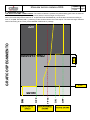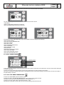
1
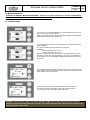
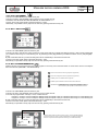
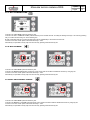
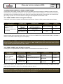
Ver. 1 del 12/03/2012
RDS Technical Manual
Cap
Pag
1
1
INTRODUCTIONThe pellet stove is a heating device with internal combustion that take the air from the room
and transform it into hot air.
The heat process is generated by the fuel (the pellet) and combustion (the air)which combination result as:
1)
Energy, the flame, consequently heat
2)
Combustion residue that is not transformed in energy, the ash
To optimize the production of the energy, we should know the chemical composition of the pellet wood and consequently calculate the volume of air requested to burn it, optimizing the combustion. This ratio is called stoichiometric
ratio.
As much as closer we can get the stove working with the ideal stoichiometric ratio, compared to the chemical composition of the pellet, the better is the combustion and the production of energy .
WHAT IS THE RDS TECHNOLOGY AND HOW IT WORKS !?
The RDS system gives the possibility to the stove to constantly control the volume of air requested for the combustion, in relation to the ideal stoichiometric ratio preset by us.
The system adapts itself to different working conditions such as:
Different wood pellet quality : the stoichiometric ratio change, the RDS system “feel” the different requirement
of air and “order” the stove to reset the preset ratio
Different size of the chimney : the stoichiometric ratio change, the RDS system “feel” the different requirement
of air and “order” the stove to reset the preset ratio.
With the RDS system, the stoves is always working with the ideal efficiency, adapting itself to different condition of
combustion air and the chemical composition of pellet .
THE FLOW METER
FLOW METER Is the instrument that can measure the flow of air requested
for the combustion. Connected to an electronic device, measuring the speed
of the air, it can adjust the correct volume of air requested for the combustion
of the stove.
Is the instrument that can measure the flow of air requested for the combustion. Connected to an electronic device,
measuring the speed of the air, it can adjust the correct volume of air requested for the combustion of the stove.
There are two temperature sensors; a simple one (sensor A) and a second one , similar to the first one, but preheated
(sensor B).
The temperature values detected by the two sensors are different.
The sensor A feel the room temperature, while the sensor B, feel the temperature of the preheated sensor.
Placing the two sensors of the flow meter in a tube where a flow of air is passing, the temperature of the sensor B
will reduce depending from the speed of the air passing inside the tube; values change depending from the speed of
the air passing inside the tube.
The main electronic board can detect the temperature modification of the two sensors and can calculate the speed of
the air accordingly.
If we multiply the value by the diameter of the tube, you will get the flow of air in m3/s passing through the system. In
a volume (m3) there is a specific mass of air; multiplying this value for the flow of air, we can obtain the mass of air
entering in the combustion chamber of the stove.
Ver. 1 del 12/03/2012
Manuale tecnico sistema RDS
Capitolo
Pagina
2
1
FUNTIONNING OF THE STOVE WITH RDS TECHNOLOGY
2.1. STARTING MESSAGE
After few seconds from switching on of the power, the following messages are displayed:
2.2. START UP CONDTION OF THE STOVE
There are two start up conditions of the stove:
-
Cold ignition (t. smokes <= then the switch off parameter TF15 )
Hot ignition or “restart” (t. smokes > lower then switch off parameter TF15)
2.2.1 “COLD” IGNITION PHASE – STOVE STATUS “COLD”
This phase refers to every ignition phase with a temperature below the minimum threshold (TF15)
A pellet stove is working with 5 different phases:
A – IGNITION PHASE
B – FLAME STABILISATION PHASE
C – WORKING PHASE
D – MODULATION PHASE
E – CONFORT CLIMA ACTIVATION PHASE
F –SWITCHING OFF PHASE
A - IGNITION PHASE
Stove in “FINAL CLEANING “ or “OFF, with attempt to ignite :
OK
-If the temperature of the smokes is higher than the parameter TF15 (Tsmoke >TF15),the stove continue the cleaning
phase.
-if the temperature of the smokes is less or equal off threshold (Tsmoke >=TF15) , a TF45 timer is activated (REIGNITION BLOCK) THE DISPLAY SHOWS “FAN WAITING IGNITION”: at the end of this time, the stove goes on
IGNITION phase.
IMPORTANT : the above-mentioned timer (TF45) has been introduced in order to guarantee that
there is no flame or unburned pellet inside the fire pot before the stove switch on.
DISPLAY SHOWING “START” : in his phase the ignitor is pre-heated for a preset time, connected to parameter TF 04. In this phase, the loading of the pellet starts according to TF01,
DISPLAY SHOWING “WAITING FLAME” : in this phase, while the ignitor is still workings, loading of the
pellet continue, the smoke fan starts and the flow meter starts to measure the flow of combustion air passing from the firepot and set the air volume as per the value TF 03 (the rpm of the smoke fan varies in order
to keep a constant the volume of air). In this moment, the T0 value is memorized as a reference to read the
smoke temperature increase (TF05 DELTA FLAME) and determine later the stove to pass into phase “FLAME LIGTH”. The loading of the pellet is regulated by TF01 which indicates the ON values of the gearmotor.
To prevent a surplus of pellet into the firepot, we activated a parameter TF02 that limit the loading time of the
pellet during all start up procedure.
Ver. 1 del 12/03/2012
Manuale tecnico sistema RDS
Capitolo
Pagina
2
2
NB. : If in the working time set for the auger to feed the pellet (TF 02), the motherboard read an increase of
temperature equal to the value set in the parameter TF 05, the stove pass from the phase WAITING FLAME
Into the phase FLAME LIGTH, without considering this time.
NB.: if the motherboard does not feel an increase of temperature equal to the value set in TF05 within the
time of “time out” (TF 48), the stove pass into “NO INGNITION ALARM”.
B) Flame stabilization phase
DISPLAY SHOWING “FLAME LIGTH” : in this phase the ignitor goes automatically in OFF status; the flow of
air goes at a value set by parameter TF10. The functioning of the auger is set by parameter TF08 the flame
has few minutes (TF09) to get stabilized.
During this working phase, which duration is measured in minutes (TF09), a check is done on smoke temperature. The system memorize the smoke temperature T0 at the beginning of this phase.
Then, every one minute, a test is done to be sure that the smoke temperature increase regularly; in the contrary, the display will show “AL11 – WRONG FLAME”.
C – WORKING PHASE
DISPLAY SHOWING “WORK” : the stove perform all power from PT01 to PT05 and then goes to working power set by the customer, while the heat exchanger, if the parameter TF 06 “fan threshold” is achieved,
It goes to the working speed set by the customer.
When the stove reaches the working phase , reaching the preset power, the air flow and the auger operate
according to parameters set for the working power selected (TF 17 – TF 20 – TF23 – TF 26 – TF 29) for the air,
TF16 – TF19 – TF 22 – TF 25 – TF 28 for the auger, TF 18 - TF 21 – TF 24 – TF 27 – TF 30 for the heat exchanger)
Each time a working power is modified, the stove reaches the set power increasing or decreasing stepless,
the power as follow:
DECREASE IN POWER
INCREASE IN POWER
Power
Time
Power
Time
from P5 to P4
40’’
from P1 to P2
40’’
from P4 to P3
40’’
from P2 to P3
40’’
from P3 to P2
40’’
from P3 to P4
40’’
from P2 to P1
40’’
from P4 to P5
40’’
If, during the work phase, the smoke temperature reaches the maximum threshold (TF 42) the stove goes into ventilation
to reduce the smoke temperature. If the ventilation is not sufficient and the temperature continues to increase, reaching
269 ° C/ 516 F the stove automatically goes into „SMOKE OVER TEMPERATURE ALARM“.
If the switchboard indicates a constant decrease in temperature due to extinction of the flame, the stove goes to ”NO
PELLET ALARM” reaching the threshold set in the parameter TF 41 (“NO PELLET THRESHOLD“) .
IMPORTANT!!! Even if the smoke temp. reaches the value set in the TF 06, the exchanger does not switch on
until the stove goes to WORK mode; this condition is necessary in order to avoid “jumps” in the Tsmoke in
FLAME LIGHT, with the risk of displaying an unusual AL 11 FLAME ANOMALY ALARM.
THE DISPLAY SHOWS “FIRE POT CLEANING”: in this phase the stove cleans the fire pot according to the interval between cleaning operations of TF 13. The duration of each cleaning operation is regulated by the parameter TF 12. The smoke extractor turns according to the TF 14 settings with a pellet load of TF 11.
The purpose of this function is to prevent the basket from clogging when the stove remains in operation for
many hours during the day.
Ver. 1 del 12/03/2012
Manuale tecnico sistema RDS
Capitolo
Pagina
2
4
D- Modulation phase
THE DISPLAY SHOWS “MODULATION WORK”: when the set room temperature is reached, independently
from the working power of the stove, it goes to working power 1.
E - Comfort clima
To activate the comfort clima please set a value different from OFF using
keys 1 and 2. Then confirms with OK.
Set the time during which the stove should stay in MODULATION WORK
before going into ECO STOP (default 4’).
The set value (in this case 5°C) has activated the function Comfort Clima.
FUNCTIONING:
The value control the restart temperature of the stove.
EXAMPLE:
Room temperature set at 21°C.
Comfort clima value set at 5°C.
With this regulation the stove will switch off once reached the 21°C and
will switch on when the room temperature is 15°C (21°C-5-0,5 tolerance =
approximately 15°C). on the display will appear the lines as in the picture
on the left.
The modulation phase is activated because the set room temperature has
been reached. If this temperature is keep for the set time of “DELAY COMFORT CLIMA” the stove switch off.
After the switching off phase the writing ECO STOP will appear on
the display. The stove will remain in this status until decrease to
15°C, only at that time the starting phase will begin.
REMARK: the functioning of the stove with COMFORT CLIMA mode could activate the ignition and the
switching off phase several times during the day; this could compromise the duration of the candle for the
automatic ignition of the stove.
Ver. 1 del 12/03/2012
Manuale tecnico sistema RDS
Capitolo
Pagina
2
5
F - Switching off phase
THE DISPLAY SHOWS “FINAL CLEAN”: The switch-off button is pressed, the pellet loading gear-motor is switched
off, the smoke extractor goes to maximum power and the heat exchanger runs at power 5.
When the smoke temperature reaches TF 15 (EXTINCTION THRESHOLD), the final clean continues according to
time TF 46 (MIN: EXTINCTION T.“) switching off the smoke extractor when this expires. The heat exchanger switches
itself off according to the TF 06 (“EXCHANGER THRESHOLD“) settings.
TF46
FINAL CLEANING
OFF
OFF
TF 15
SMOKE
TEMPERATURE
OFF
ON
SMOKE ENGINE
ON
ON
WORK
STOVE
CONDITIONS
GRAFICO SPEGNIMENTO
OFF
Ver. 1 del 12/03/2012
Manuale tecnico sistema RDS
Capitolo
Pagina
2
6
4.2.2 “HOT” re-ignition phase - STOVE STATUS “HOT“
This phase refers to every ignition cycle with temperature below the re-start threshold (TF 07), in any case over the minimum threshold (TF 15,say when the stoves is already hot).
N.B. : the value relating to the restart threshold is a datum tested in the company on each of our stove models in
order to identify the optimal restart condition. This parameter should not be changed significantly by the service
centre (not over 5° C/10° F) unless Ecoteck technical centre has been consulted.
A pellet stove in these conditions functions in 5 phases:
A - RE-IGNITION PHASE
B - FLAME STABILISATION PHASE (see previous section)
C - WORK PHASE (see previous section)
D - MODULATION PHASE (see previous section)
E - COMFORT CLIMATE ACTIVATION PHASE (see previous section)
D - SWITCH OFF PHASE (see previous section)
A – Re-ignition phase
Re-ignition conditions:
Stove in “FINAL CLEAN“ with re-ignition attempt:
- if the smoke temperature is lower than or the same as the restart threshold (Tsmoke<=TF07), and in any case over
PR13 “SWITCH OFF PHASE”, the SWITCH OFF PR” switches on the TF 45 timer (RE-IGNITION BLOCK). After the time
the stove goes into re-ignition state;
- if the smoke temperature is higher than the restart threshold (Tsmoke>TF07) the stove continues with the final clean;
after this threshold has been reached, the TF45 (RE-IGNITION BLOCK) timer switches on and the stove goes into that
re-ignition state;
In both cases, during the period before re-ignition, the message “FAN WAITING RE-IGNITION” will appear on the display.
RE-IGNITION : pre-heating of the ignitor for an established time, linked to the parameter “PREHEATING TIME TF04“. In
this phase pellet loading starts according to TF01 while the smoke extractor, which previously was carrying out the final
clean, slows its revs and positions itself on the value set at TF09(fan speed in FLAME PRESENT phase.
IMPORTANT!!!This method makes it possible to solve the problem with the smoke extractor, which, passing
from the OFF phase to the activation phase, could cause an anomalous increase in temperature which could
elude the TF05 “FLAME DELTA “ when a flame is present.
N.B . : For all the other phases, the stove behaves in the same operating way as a normal ignition (See paragraph 1.2.1 from point B).
Ver. 1 del 12/03/2012
Manuale tecnico sistema RDS
Capitolo
Pagina
3
1
3.Description of the functioning and symbology of the display
The innovation of this particular display is the communication through low voltage conveyed waves (12 volts) between the electronic motherboard and the display. The communication is made trough a bipolar cable (ex: the cable for the stereo speakers) and the novelty is the
possibility to install the display in the wall using the optional standard frame for electrical box 503.
3.1. Display with mode “BASE”
Calendario
Orologio
Potenza di lavoro
Temperatura ambiente
Stato stufa
.
Key “1”: access key to “set room temperature” and regulation
Key “2”: access key to “set power” and regulation
Key “OK”: short press of the key to confirm and come back to the main screen; press the key 3 seconds long to switch on and
switch off the stove.
The functionalities of this display when used in mode “BASE” are:
-Switch on and switch off of the stove
-Set of the room temperature and selection of the type of sensor (supplied sensor connected to the motherboard or sensor integrated to the
display)
-Set of the working power (1,2,3,4,5)
3.1.1. switch on and switch off of the stove
Before starting the stove please follow following procedure :
1Connect the power cable
2Set the switch on the backside of the stove on position 1
3Check that the installation is connected to the chimney
4Load the pellet tank with 6 mm pellets
5Load the screw as described in paragraph 8.6
6Press key OK for 3 seconds long.
At this stage the stove will begin the ignition phase.
On the display will appear following writings:
-START (waiting time is different depending on default settings)
-WAITING FLAME (waiting time is different depending on default settings)
-FLAME LIGHT (waiting time is different depending on default settings)
-WORK (waiting time is different depending on default settings)
3.1.2. Set of the room temperature
Fig. 1
Fig. 2
The functioning of the stove with room thermostat activated is of 3 types:
-With supplied room sensor positioned on the backside of the stove ( not available for insert models)
-With room sensor integrated to the display
-With external thermostat (not supplied)
MODE WITH SUPPLIED ROOM SENSOR (DEFAULT AND SUGGESTED USE)
If you use the supplied room sensor , the display will show the room temperature.
To set and modify the room temperature press key number 1 to enter in the dedicated menu and set the desired value with key 1 and 2.
Confirm with key OK 2 times and keep deselected the box SENSOR CONSOLLE (flag, see pic.2). Once reached the set temperature
the display will show MODULATION WORK, so the stove will reduce to minimum the pellet consumption and the power as well.
Ver. 1 del 12/03/2012
Capitolo
Manuale tecnico sistema RDS
Pagina
3
2
Confermare con il tasto OK due volte mantenendo deselezionata la casella (flag, vedi fig. 2) Sonda Consolle.
Al raggiungimento della temperatura, sul display verrà visualizzata la scritta LAVORO MODULA, in questo caso la stufa ridurrà al minimo
il consumo dei pellet diminuendo la potenza di riscaldamento.
MODE WITH ROOM SENSOR INTEGRATED TO THE DISPLAY
in case you want to install the display on the wall instead of on the stove as from the factory, please reference to the functioning with
supplied room sensor (as above explicated) with just one difference: the box (flag) SENSOR CONSOLLE, if you work in this mode,
should be selected by using key 2. Then confirm with the key OK ( reference ti
o pic. 1 paragraph 7.1.2.)
MODALITA’ TERMOSTATO ESTERNO
if you use an external thermostat correctly connected as shown in the electrical scheme ( reference paragraph 10), the display will not show
the room temperature but the writing T ON ( when the contact is closed) or T OFF ( when the contact is open).
REMARK: TO ENABLE THE EXTERNAL THERMOSTAT ENTER IN THE SET TEMPERATURE USING KEY 1 AND THEN PRESS REPEATEDLY TO REACH THE VALUE “EST” ON THE DISPLAY; CONFIRM TWO TIMES WITH THE KEY OK KEEPING DESELECTED THE
BOX (FLAG) “SENSOR CONSOLLE”.
Once reached the set temperature of the thermostat the display will show MODULATION WORK, so the stove will reduce to minimum the
pellet consumption and the power as well. If activated the mode COMFORT CLIMA, the stove will switch on and off automatically (for details
reference paragraph 8.2.)
N.PEL.
N.H2O
N.AMB. TERM.
N.AMB. TERM.
-TC1+
Nero
Nero
Rosso
Blu
1
2
3
4
5
6
SONDA
AMBIENTE
7
8
-TC1+
9
10
TERMOSTATO SONDA FUMI
ESTERNO
REMARK: if you want to use the CONFORT CLIMA is advisable an external thermostat with OFF-SET of at
least 3°C.
3.1.3. set of the working power
To modify the working power press key 2 to enter in the dedicated menu and with keys 1 and 2 to set the power you desire from 1 to 5
and confirm with key OK. Increasing the power also the pellet consumption and the speed of the fan increase as well.
It is not possible to modify the set power during the phase of MODULATION WORK.
3.2. Display with mode “ADVANCED”
Calendario
Orologio
Potenza di lavoro
Temperatura ambiente
Stato stufa
Key “OK”: access key to the complete menu and confirmation of the settings chosen
Key “1”: scroll key and modification of the settings
Key “2”: scroll key and modification of the settings
The stove is equipped with many functions available in each menu programming. Some of these menu are accessible for the end user ,
other are protected with a password so they are accessible only for the After sales center.
Ver. 1 del 12/03/2012
Manuale tecnico sistema RDS
Capitolo
Pagina
3
3
The three pictures which follow show the menu with all its icons for the advanced functionalities
The use of the display in advanced mode provides the view of three main menus:
-USER MENU
-DEFAULT SETTINGS (protected by a password)
-BASIC PARAMETERS (protected by a password)
The submenus of the USER MENU (the only one accessible for the end user) are the following:
-Menu STOVE STATUS
-Menu SET ROOM TEMPERATURE
-Menu SET POWER
-Menu SET CLOCK
-Menu CHRONOTHERMOSTAT
-Menu LANGUAGE
-Menu COMFORT CLIMA
-Mode SILENCE
-Mode SELF CONTROL SYSTEM
-Menu VIEW SETTINGS
-Menu VIEW WORKING HOURS
-Menu SET DRAUGHT/PELLET
3.2.1 Menu “STOVE STATUS”
Velocità flusso in ingresso
Giri estrattore
Temperatura fumi
Stato della coclea
In this menu you can check the correct functioning of the most important components of the pellet stove, and some values which distinguish
its correct functioning.
To enter in this menu press 3 times the key OK after having selected the icon with the writing “Stove status”.
This menu is used both by the after sale center to understand the reason of the malfunctioning of the stove and by the end user as well for
the pellet loading in the tank.
3.2.2. menu “SET ROOM TEMPERATURE”
To enter in the USER MENU press two times key OK.
To enter in the menu “SET ROOM TEMPERATURE” press once key 2 and confirm with OK.
TO MODIFY THE SETTING PLEASE REFERENCE TO PARAGRAPH 7.1.2.
To return to the main screen press at the same time keys 1 and 2.
Alternatively it is possible to exit by step from the menus by pressing each time the key OK.
Ver. 1 del 12/03/2012
Manuale tecnico sistema RDS
Capitolo
Pagina
3
4
3.2.3. menu “SET POWER”
To enter in the USER MENU press two times key OK.
To enter in the menu “SET POWER” press 2 times key 2 and confirm with OK.
TO MODIFY THE SETTING PLEASE REFERENCE TO PARAGRAPH 7.1.3.
To return to the main screen press at the same time keys 1 and 2.
Alternatively it is possible to exit by step from the menus by pressing each time the key OK.
3.2.4. Menu “SET CLOCK”
To enter in the USER MENU press two times key OK.
To enter in the menu “SET CLOCK” press 3 times key 2 and confirm with OK. To modify the settings use keys 1 and 2 and by pressing OK
you confirm the data and go on to the following one. By activating the box (flag) ON/OFF you enable the function chrono ( see paragraph
7.2.5.)
By last confirmation with OK you save all settings and return automatically to the screen with the icons.
To return to the main screen press at the same time keys 1 and 2.
Alternatively it is possible to exit by step from the menus by pressing each time the key OK.
3.2.5. Menu “CHRONOTHERMOSTAT”
With the function chrono thermostat is possible to program for each day of the week the switch on and off of the stove in two independent intervals time (PROGAM 1 and PROGRAM 2).
START: orario di accensione del crono (programma1-programma2)
STOP: orario di spegnimento del crono (programma1-programma2)
GIORNO: giorni in cui si desidera attivare i programmi
POTENZA: potenza desiderata al momento dell’accensione della stufa
TEMPERATURA: temperatura ideale che si vuol raggiungere nell’ambiente in cui la stufa
è installata durante l’avvio con crono attivo.Il settaggio in questione
viene sovrascritto a quello impostato in condizioni di lavoro manuale.
To enter in the USER MENU press two times key OK.
To enter in the menu “SET POWER” press 4 times key 2 and confirm with OK.
To choose the programmation use keys 1 and 2; confirms with OK.
Program 1: use keys 1 and 2 to modify the settings and by each press of OK you confirm the data and go on to the following one.
Program 2: use keys 1 and 2 to modify the settings and by each press of OK you confirm the data and go on to the following one.
By last confirmation with OK you save all settings and return automatically to the screen with the icons.
To return to the main screen press at the same time keys 1 and 2.
Alternatively it is possible to exit by step from the menus by pressing each time the key OK.
Il simbolo indicato seganla che è attiva la funzione crono. E’ comunque possibile effettuare la
programmazione del crono anche se questo risulta disattivato. Per renderla funzionante fare
riferimento al capitolo dedicato all’impostazione dell’orologio (5.2.4 MENU OROLOGIO).
Ver. 1 del 12/03/2012
Manuale tecnico sistema RDS
Capitolo
Pagina
3
5
DESCRIZIONE DELLE STRINGHE :
Descrizione
START PROG - 1
STOP PROG - 1
GIORNO PROG - 1
Valori impostabili
Da OFF a 23:50 a step di 10’
Da OFF a 23:50 a step di 10’
Tra on/off per i giorni da lunedì a domenica
POTENZA PROG - 1
Da 01 a 05
SET TAMB PROG - 1
Da EST a MAN
START PROG - 2
STOP PROG - 2
GIORNO PROG - 2
Da OFF a 23:50 a step di 10’
Da OFF a 23:50 a step di 10’
Tra on/off per i giorni da lunedì a domenica
POTENZA PROG - 2
Da 01 a 05
SET TAMB PROG - 2
Da EST a MAN
ESEMPIO:
Suppose that the user want to switch on the stove at 08:30 with set switch off at 21:30 all days of the week with the exception of the weekend
(PROGRAM 1), suppose moreover that the user want a room temperature of 21°C and to reach this temperature he sets a working power of
3. The passages to do will be the following:
From the MENU CHRONO confirm with key OK and set the program you want to modify using key 1 and 2;
By confirming with key OK you go to the set of the switch on hour, set the hour (hh:mm) using keys 1 and 2;
By confirming with key OK you go to the set of the switch off hour, set the hour (hh:mm) using keys 1 and 2;
By confirming with key OK you go to the scroll of the days, with keys 1 and 2 activate/deactivate the days (ex: Monday, Tuesday,
Wednesday, Thursday and Friday active).
By confirming with key OK you go to the set of the power, with keys 1 and 2 set the value (ex: Power 3).
By confirming with key OK you go to the set of the room temperature, with keys 1 and 2 set set the degrees (ex: 20°C).
When the stove is working and the set room temperature is reached the stove goes into MODULATION or COMFORT CLIAMA (if activated).
! IMPORTANT
BY USING THIS MODE IT IS NECESSARY TO CHECK THAT AFTER EVERY AUTOMATIC
SWITCHING OFF THE FIREPOT IS ALWAYS WELL CLENAED IN ORDER TO GUARANTEE A PERFECT AUTOMATIC IGNITION.
3.2.6 menu “LANGUAGE”
To enter in the USER MENU press two times key OK.
To enter in the menu “SET LANGUAGE” press 5 times key 2 and confirm with OK. To select language please use keys 1 and 2.
By last confirmation with OK you save all settings and return automatically to the screen with the icons.
To return to the main screen press at the same time keys 1 and 2.
Alternatively it is possible to exit by step from the menus by pressing each time the key OK.
Ver. 1 del 12/03/2012
Manuale tecnico sistema RDS
Capitolo
Pagina
3
6
3.2.7. Menu “COMFORT CLIMA”
To enter in the USER MENU press two times key OK.
To enter in the menu “COMFORT CLIMA” press 6 times key 2 and confirm with OK. To modify the settings use keys 1 and 2 and by pressing
OK you confirm the data and go on to the following one.
By last confirmation with OK you save all settings and return automatically to the screen with the icons.
To return to the main screen press at the same time keys 1 and 2.
Alternatively it is possible to exit by step from the menus by pressing each time the key OK.
3.2.8. Mode “SILENCE”
To enter in the USER MENU press two times key OK.
To enter in the MODE SILENCE press 7 times key 2 and confirm with OK. Enable or disable the function by using key OK.
To return to the main screen press at the same time keys 1 and 2.
Alternatively it is possible to exit by step from the menus by pressing each time the key OK.
3.2.9 Mode “SELF CONTROL SYSTEM”
To enter in the USER MENU press two times key OK.
To enter in the MODE S.C.SYSTEM press 8 times key 2 and confirm with OK. Enable or disable the function by using key OK.
To return to the main screen press at the same time keys 1 and 2.
Alternatively it is possible to exit by step from the menus by pressing each time the key OK.
Ver. 1 del 12/03/2012
Manuale tecnico sistema RDS
Capitolo
Pagina
3
7
3.2.10 Menu “VIEW SETTINGS“
In this menu you can verify the parameters set in the motherboard.
To enter in the USER MENU press two times key OK.
To enter in the menu “VIEW SETTINGS” press 9 times key 2. By confirming with OK you enter in the list of set parameters. To scroll the list
of parameters use key 1 and 2.
To return to the main screen press at the same time keys 1 and 2.
Alternatively it is possible to exit by step from the menus by pressing each time the key OK.
3.2.11. Menu “VIEW WORKING HOURS”
In the menu VIEW WORKING HOURS you can check the total or partial working hours and also the number of ignitions of the stove. It is
possible sometimes that the working hours are not reset and you see numbers like 5000/15000/25000. It will be care of the technician to reset these numbers by first ignition. This does not means that the stove has already worked for so many hours, it is just a setting made during
the tests we make in Ravelli, before the stoves are packed and delivered. This menu is used by the After Sales Center to evaluate the total
working hours of the stove during the season and consequently to evaluate the need of cleaning (“service hours”).
To enter in the USER MENU press two times key OK.
To enter in the menu “VIEW WORKING HOURS” press 10 times key 2. By confirming with OK you see the working hours of the stove. To
scroll the different counters (total or partial hours and number of ignitions) use key 1 and 2.
To return to the main screen press at the same time keys 1 and 2.
Alternatively it is possible to exit by step from the menus by pressing each time the key OK.
SERVICE HOURS
All our models need in addition to the regular cleaning (reference to the paragraph dedicated to the maintenance of the stove in the
user manual), also a special cleaning which should be done by the installer (authorized by the producer).
At the time of the installation it is possible to set a number of working hours appropriate for the model following this procedure default
settings>>extra parameters>>TF53 service hours. At the end of these hours on the display will appear the message “SERVICE
HOURS” followed by an acoustic signal. When this message appears please contact the installer to do the special cleaning of the
stove.
If the cleaning is not done the message will appear by each ignition but will not interrupt the functioning of the stove.
3.2.12 Menu “SET ARIA/PELLET“
The set of the draught-pellet blend allow to modify immediately the quantity of inlet air and the quantity of pellet loaded in the firepot.
The stove is tested with pellet certified DIN PLUS. If you do not use certified pellet could be necessary to set the combustion. Normally the modification is made on the “% FLUX” to adjust the inlet air and consequently the combustion; if the regulation of the flux is not
sufficient could be necessary to adjust also the “% PELLET”.
Ver 1 of 12/03/2012
Chapter
RDS Technical Manual
Page
8
1
ALARMS
In the event that a functional anomaly is verified, the card intervenes, signals the irregularity and operates in different modes according to the type of alarm. The following alarms are foreseen.
Code
Alarm origin
Screen display
Temperature smoke probe
02
ALARM SMOKE PROBE
Smoke over-temperature
03
TEMP SMOKE ALARM
Failure to light
05
FAILURE TO LIGHT ALARM
Flame anomaly
11
FLAME ANOMALY ALARM
Extinction during work phase
06
PELLETS FINISHED ALARM
Failed mains power supply
01
BLACK-OUT
General safety pressure switch
08
DEPRESURIZATION ALARM
General safety thermostat
07
TEMPERATURE ALARM
Smoke fan unserviceable
04
EXTRACTOR UNSERVICEABLE ALARM
Extractor revolutions anomaly
12
EXTRACTOR REVOLUTIONS ALARM
Door open
13
INSUFFICIENT DRAFT ALARM
Brazier obstruction
13
INSUFFICIENT DRAFT ALARM
Unserviceable debimeter
09
UNSERVICEABLE DEBIMETER ALARM
Guasto al triac della coclea
15
TRIAC COCHLEA ALARM
Defective cabling
14
COCHLEA PHASE ALARM
Pressure <0,5bar or >2,5bar
16 rate-determining
step
PRESSURE ALARM
Water heater > 90°C (TF37)
10
HOT WATER ALARM
8.1 Allarm 02 SMOKE PROBE
Occurs in the event of incorrect reading from the smoke probe when this turns out to be unserviceable or not connected.
8.2 Alarm 03 SMOKE TEMP
Hot fumes: Is announced not as a true alarm but as a warning of having reached the
maximum TF 42 threshold. When the card signals such a condition, it intervenes by reducing the pellet load and the air inlet flow at
the PT1, while leaving the exchanger fan at PT5, in order rapidly to cool the chassis and the smoke temperature.
Smoke over-heating alarm: Occurs when the heat of fumes fails to bring the smoke probe temperature down and this displays a
temperature greater than 289°C.
8.3 Alarm 05 MANC ACC
Occurs if the TF 48 time has completely run down without verification of an increase of Tsmoke > TF 05 condition.
8.4 Alarm 11 ANOMOLOUS FLAME
Occurs if during the “FLAME PRESENT” phase an increase of the t.smoke conditions have not been verified.
8.5 Alarm 06 PELLETS FINISHED
Occurs if, at the end of the “STABILIZATION” phase, the temperature of the fumes does not reach the TF 41 value.
Or, it may occur in the “WORK” phase, when the temperature of the fumes goes below the same TF 41 value.
8.6 Alarm 01 BLACK-OUT
Activates when a missing mains power condition occurs for a time greater than the TF 44 parameter.
OPERATIONAL STABLACK OUT DURATION
TUS
NEW STATUS ON RESTORATION OF MAINS VOLTAGE
OUT
any
FINAL CLEANING (*)
SWITCHING ON
any
BLACK-OUT ALARM
WORK
< TF44
WORK (*)
WORK
> TF44
BLACK-OUT ALARM
FINAL CLEANING
any
FINAL CLEANING (*)
ECO-STOP
any
ECO-STOP (*)
(*) does not prompt ALARM condition
Ver 1 of 12/03/2012
RDS Technical Manual
Chapter
Page
8
2
8.7 Alarm 08 DEPRESSURIZATION
When the pressure switch (low pressure meter) identifies a pressure below the trigger threshold, the same intervenes to remove
power from the cochlea (in series with the power supply) and simultaneously allows the controller to acquire this change of status
through the AL1 in CN4 terminal.
8.8 Alarm 07 THERMAL
When the main safety thermostat identifies a temperature greater than the trigger threshold (circa 90°C), the same intervenes to
remove power from the cochlea (in series with the power supply) and simultaneously allows the controller to acquire this change of
status through the AL1 in CN4 terminal. The thermostat is usually mounted on the hopper (the threshold beyond which the device
opens the contact is circa 90°C).
8.9 Alarm 04 EXTRACTOR (UNSERVICEABLE)
When the smoke extractor fan becomes unserviceable or the encoder does not read the number of revolutions, even if the reader
cable is simply disconnected or broken.
8.10 Alarm 12 EXTRACTOR REVOLUTIONS
When the extractor fan works at a speed below 15% with respect to that set in the function parameters.
8.11 Alarm 13 INSUFFICIENT DRAW
When the flow value is greatly removed from the set value, for example if:
- door open: the flow goes below the minimum flow value (base parameter)
- blockage in the brazier or in the smoke ducts inside the stove body: the flow set is not
reached even with the help of the extractor which due to the circumstance is driven at its maximum
working level (maximum domestic network voltage). After a certain time in which the stove is in this
condition, the alarm goes off.
8.12 Alarm 09 UNSERVICEABLE DEBIMETER
In the event in which an unserviceablility is verified of the debimeter reading the input air flow.
When this anomaly occurs, the stove function is not interrupted, indeed, the machine starts to work in module mode functioning in
manual (RDS removed). A periodic signal nevertheless remains active, whether visual or acoustic, indicating the type of problem.
8.13 Alarm 15 TRIAC COCHLEA
When the triac (which manages the ON and OFF pellet loading phases) inside the electronic card is unserviceable,
the cochlea de-activates and this alarm appears on the display.
8.14 Alarm 14 COCHLEA PHASE
In the case in which the cochlea wiring is not correctly connected on the card or there are interruptions.
Check the various connections and the condition of the cable.
Alarms relating to the stoves (gamma HYDRO)
8.15 Alarm 16 PRESSURE (WATER)
In the case in which the plant pressure is greater or less than a value set by the Ravelli srl company (must be between 0.6 bar and
2.4 bar). A pressure of circa 1.0 bar is recommended at cold circuit.
8.16 Alarm 10 HOT WATER
If the water heater temperature exceeds 90°C (TF37) the following alarm is screened. In this case, it is important to check for correct functioning of the circulator or whether some impedence (gate valve) is causing incorrect circulation of water in the heating
circuit.
NB: Each alarm condition (excluding alarm 09) causes the immediate switching off of the stove, with
the extactor active at maximum power and the exchanger at PT5 speed until reaching the dedicated
TF06 threshold. The alarm status is reached after TF43 time can be zeroed by pressing the OK button.
IMPORTANT! Each alarm is only displayed after a time has elapsed as established in
the TF 43 timer “Alarm Delay” parameter, with the exception of the “PELLET FINISHED“, “BLACK-OUT”
e “DEBIMETER UNSERVICEABLE“ alarms.
IMPORTANT! When an alarm is activated, it is no longer possible to start the stove until that alarm
is reset by holding the OK button pressed.
Ver. 1 del 12/03/2012
10
1
Capitolo
Manuale tecnico sistema RDS
Pagina
10.OPERATIONS LINKED TO “FINAL CLEAN” PHASE
The purpose of the “FINAL CLEAN” phase is to burn all pellets in the fire pot during the extinction phase. In fact the
smoke extractor is activated at maximum revs per minute. Its value is around 2700 rpm. In just a few minutes the surplus pellet is burnt in the basket and the stove starts the cooling phase also thanks to the support of the heat exchanger running at power of 5 until it succeeds in lowering smoke temperature till threshold TF 06.
10.1 “FINAL CLEAN” without Re-ignition attempt
If extinction of the stove is required, the switchboard activates the “FINAL CLEAN” phase and behaves as follows:
EXTINCTION
REQUEST
-OK for 4 seconds
- Shut off
CHRONOTHERMOSTAT
ECO STOP
CONDITIONS
OPERATION
SMOKE
TEMP.>TF15
SMOKE
TEMP.<=TF15
T.FUMI<TF 15
after TIMER TF 46
FINAL CLEANING (until
following condition)
FINAL CLEANING (until
timer TF46)
//
DISPLAY
EFFECT
FINAL CLEANING
OFF
FINAL CLEANING
OFF
OFF
//
After the smoke probe has reached the value set in the TF15, the TIMER TF46 (“T-MIN EXTINCTION”) is activated in
order to check that the flame has gone out completely.
IMPORTANT!!! the TIMER mentioned above, that can be set manually by the PR40, must have a value equal to
the time needed to extinguish the flame, even after the “WAIT FLAME” phase where the firepot must consume
a large amount of pellets before the “OFF” status.
10.2 “FINAL CLEAN” with Re-ignition attempt
If a Re-ignition is requested after the “FINAL CLEAN”, the switchboard must behave as follows:
EXTINCTION
REQUEST
CONDITIONS
OPERATION
SMOKE
FINAL CLEANING (until next
TEMP.>TF07
condition)
- OK for 4 seconds
T.SMOKE<=TF07
- Ignition with
& SMOKE
FINAL CLEAN (until TF45
CRONOTHERMOSTAT
TEMP.>TF15
- Ignition with COMFORT
FINAL CLEAN (until TF45
T.SMOKE<TF07
timer)
DISPLAY
EFFECT
FAN WAIT
RE-START
RE-START
FAN WAIT
RE-START
RE-START
FAN WAIT
RE-START
START
Before every START - RE-START phase, the stove carries out a further final clean according to TIMER TF45 (“REIGNITION BLOCKAGE“) in order to burn all pellets inside the fire pot.
.
IMPORTANT!!! the TIMER mentioned above, that can be set manually by the TF45, must have a value equal to
the time needed to extinguish the flame, even at high temperatures.