1
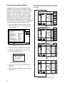
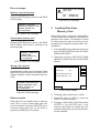
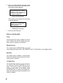
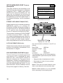
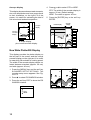
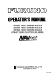
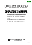
12/30/1999
OPERATOR’S MANUAL
ADDENDUM
Model: GP1650/1850 Series
Subject: New FISHING MODE and
Feature Enhancements
This Furuno GP1650/1850 Series Plotter
has a newly developed software revision
that includes many exciting new features.
This addendum is a supplement to your
Operator’s Manual. It describes these new
features and explains how to utilize them.
1
TABLE OF CONTENTS
A.
B.
C.
D.
E.
F.
G.
H.
Explanation of New Features…………………….………….… 2
Operator’s Manual Information………………….…………….. 3
Software Revision Check……………………….………..……. 3
New Fishing Modes and Mark Function…………………….… 5
New Memory Card Storage Function………………………….. 8
Navionics “Nav-Chart” Cartography “OFFSET” Capability…11
RTCM DGPS Data Output(1650/1850 “D”/”DF” ONLY)……12
New “Wide-Screen” E/S Mode(1650/1850 “F”/”DF” ONLY)..13
A. Explanation of New Features:
1. New "Fishing Plotter Mode": This feature allows you to place your
GP1650/1850 in either a "Pleasure Mode" or a "Fishing Mode". In
the "Pleasure Mode", the GP1650/1850 operates the same as
previous software revisions.
In the new Fishing Mode, you can place Marks and Line Points (Up
To 5000) in internal memory. The mode also allows you to change
Track Colors, Start/Stop Own Ship Tracking, and Edit Mark Entries
easily from a newly added Softkey Menu. In “Pleasure Mode”, this
new Softkey Menu is not displayed.
2. New "Memory Card Storage" Capability: It is now possible to
store Marks/Lines, Waypoints/Routes, Tracks, and Configuration
Information (Menu Settings) of the GP1650/1850 Series onto a
memory card. The entire memory contents of a GP1650/1850 can be
stored into a single memory card for storage or cloning your
GP1650/1850. This provision allows Unlimited Data Storage for the
GP1650/1850 Series. Uploading/Downloading Waypoint
information via the RS232 PC Interface has remained unchanged.
The part number for the RAM Storage Card is 000-140-483. It is
available from any authorized Furuno Dealer.
3. RTCM DGPS Data Output: It is now possible to send RTCM 104,
Differential Correction Data, to other Differential-Ready GPS
Products on your vessel. This feature requires a "D" or ”DF” version.
2
4. Navionics Cartography "OFFSET" Capability: This new
software allows operators to OFFSET Navionics Charts. Previous
software versions did not have this capability.
5. "Wide-Screen" Echo Sounder Mode: When operating in the “Split
Screen” mode (Plotter and Sounder display), this function allows the
user to select between the wide (50%) or narrow (25%) sounder
screen. This feature requires a “F” or “DF” version.
B. Operator’s Manual – The Operator’s Manual included with your
GP1650/1850 is not updated at this time. We will offer revised
Operator’s Manuals late in the first quarter of 2000.
Please call your authorized Furuno Dealer for further information.
This software revision does not effect the Installation Manual included
with your GP1650/1850.
C. Software Revision Check (For Confirmation Only) - The
Software Revision of your GP1650/1850 can be found by using the “Self
Test” procedure on page 4.
The “Memory I/O” test will display the software revision number in the
upper left corner of the display.
The last two digits of the number indicate which software version is
currently installed.
If your revision number is lower than the ones listed below, a simple
software upgrade for any GP1650/1850 is all that is necessary to take
advantage of the new features available.
Call your local Furuno Dealership for more information.
-GP1650/GP1650D
-GP1650F/GP1650DF
-GP1850D
-GP1850DF
3
Software Version 145-1801-013 and higher
Software Version 145-1802-011 and higher
Software Version 145-1826-006 and higher
Software Version 145-1827-006 and higher
4. Press the soft key SELF TEST to open
the test menu.
Diagnostic Tests
Memory, I/O port test
TEST
This test conducts a general check of the display unit and the antenna unit. The unit displays the results for each device or
component checked as OK or NG (No Good).
MEMORY•I/O TEST
KEYBOARD TEST
TEST PATTERN
1. Press the [MENU] key to open the main
menu.
2. Press the soft key CONFIGURATION to
show the configuration menu.
CONFIG
SETUP NMEA PORT 1
SETUP NMEA/DGPS PORT 2
REMOTE CONTROLLER TEST
DGPS 3D
Figure 12-3 Test menu
5. Press the soft key MEMORY•I/O TEST
to start the test. Test results and program
nos. are shown as below.
UPLOAD/DOWNLOAD DATA
TEST
SYSTEM MENU
PROGRAM: OK
No. (LOOK HERE)
DGPS 3D
RETURN
RETURN
SRAM: OK
INTERNAL
BATTERY: OK
GPS
RECEIVER: OK
No.(Doesn't Matter)
Figure 12-1 Configuration menu
3. Press the soft key SYSTEM MENU to
open the system menu.
DRAM: OK
PORT1: OK
PORT2: OK
BEACON
RECEIVER: OK
No.(Doesn't Matter)
No.
RETURN
SYSTEM
MENU
SELF TEST
DEMONSTRATION MODE
RETURN
Figure 12-2 System menu
4
Figure 12-4 Memory, I/O test results
6. The test runs continuously. To return to
the self test menu, press the soft key
RETURN.
MEMORY CLEAR
DGPS 3D
NOTE: Special connections are required to check PORT1
and PORT2 otherwise, "--" appears.
Note: BEACON RECEIVER results only appear on GP-1650/1850 "D" and "DF" Ver.
Changing Operation Mode
Operation mode can be changed between
PLEASURE and FISHING. FISHING mode
provides mark/line entries on the PLOTTER
display. Up to 5000 Marks can be entered
together with track points. Apportioning
between track and mark memory can be
changed by menu. Pressing the [HIDE/
SHOW] key changes the function of soft keys.
Holding tracks, changing track color, selecting mark colors, and the type of marks/lines
can be performed by the soft keys directly.
1. Press the [MENU] key and the soft key
DISPLAY OPTIONS. The display setup1
menu appears.
RNG & BRG MODE
RANGE/SPEED UNIT
DEPTH UNIT
TEMP UNIT
LAT/LON DISPLAY
TIME DISPLAY
WAYPOINTS SW
COURSE VECTOR
BEARING
MAG VARIATION
TD DISPLAY
POSITION DISPLAY
SET GO TO METHOD
s OPERATION MODE
RHUMB LINE
nm / kt
ft
F
DD MM.MMM'
24 HOUR
AUTO2
LINE
MAGNETIC
AUTO 01.3 E
LORAN C
LAT/LON
1 POINT
PLEASURE
34 12.345’ N
135 12.345’ E
CSE 245.8
SPD 16.3kt
COURSE
UP
ZOOM
QP<01>
IN
ZOOM
OUT
AUTO
C.U.
NAV
WPT
DGPS 3D
Press the [HIDE/SHOW] key.
34 12.345’ N
135 12.345’ E
DISPLAY
SETUP1
CSE 245.8
SPD 16.3kt
COURSE
UP
HOLD
QP<01>
TRACK
COLOR
EDIT
MARK
ENTRY
MARK
EDIT
NAV
WPT
DGPS 3D
Press the [HIDE/SHOW] key.
RETURN
DGPS 3D
In the FISHING mode, pressing the [HIDE/
SHOW] key changes the function of soft keys
as follows.
34 12.345’ N
135 12.345’ E
Display setup1 menu
CSE 245.8
SPD 16.3kt
COURSE
UP
QP<01>
2. Press ▼ to select OPERATION MODE.
3. Press the soft key EDIT to show the OPERATION MODE window.
OPERATION MODE
DGPS 3D
▲
' PLEASURE
™ FISHING
▼
Press the [HIDE/SHOW] key.
OPERATION MODE window
QP<01>
4. Press ▲ or ▼ to select PLEASURE or
FISHING.
5. Press the soft key ENTER or the [ENTER]
key to finish.
DGPS 3D
Press the [HIDE/SHOW] key.
Changing displays by Scrolling
5
MARKS
1
Entering Marks
Select the Fishing Mode to enable entry of
marks on the PLOTTER display. Select the
location desired with the cursor, or turn off
the cursor to enter the mark at own ship position. Pressing the [HIDE/SHOW] key changes
the function of soft keys. Press the soft key
MARK ENTRY to enter a new mark. The mark
is entered in the shape and color selected
from the MARK SHAPE and MARK COLOR
selection windows.
2
Changing Mark Attributes
MARK SHAPE
▲
' ™
™
™
™ ✕
™
™
™
▼
MARK SHAPE window
Mark line
Press the soft key MARK LINE to display
the MARK LINE window. Press ▲ or ▼ to
select mark line desired.
MARK LINE
▲
'
™
™
™
▼
You can select the shapes, line types and colors
of Marks and Lines on the TRACK display.
1. Press the [HIDE/SHOW] key to show the
soft key MARK EDIT.
2. Press the soft key MARK EDIT to show
the MARK/LINE window.
MARK LINE window
Mark color
MARK SHAPE
.
MARK LINE
MARK COLOR
Press the soft key MARK COLOR to display the MARK COLOR window. Press
▲ or ▼ to select mark color desired.
YELLOW
MARK/LINE window
3. Press the soft key MARK SHAPE to
change mark shape, the soft key MARK
LINE to change mark line, or the soft key
MARK COLOR to change mark color.
Mark shape
Press the soft key MARK SHAPE to display the MARK SHAPE window. Press ▲
or ▼ to select mark shape desired.
MARK COLOR
▲
' RED
™ YELLOW
™ GREEN
™ LIGHT BLUE
™ PURPLE
™ BLUE
™ WHITE
▼
MARK COLOR window
4. Press the soft key ENTER or the [ENTER]
key.
5. Press the soft key RETURN to finish.
Marks/lines entered hereafter are inscribed
in the shape, color and line type selected
here.
6
3
Changing Mark Size
4
Erasing Marks
Mark size can be selected from STD (standard) and SMALL.
Erasing individual marks/lines
1. Press the [MENU] key to display the main
menu.
1. Operate the cursor pad to place the cursor on the mark you want to erase.
2. Press the soft key CHART SETUP OPTIONS.
2. Press the [CLEAR] key. The mark selected is erased.
3. Press the soft key CHART DETAIL to
open the CHART DETAIL menu.
sLAT/LON
GRID
TEXT INFO
WAYPOINT
WAYPOINT NAME
INDEX
LANDMASS
BACKGROUND
NAV AIDS
SECTOR INFO
OTHER SYMBOLS
MARK SIZE
GREEN
ON
LARGE
ON
ON
BRT YELLOW
BLUE
ON
OFF
WHITE
STD
DGPS 3D
Note: To erase a line, place the cursor
on the edge of the line. The line segment
will be erased.
CHART
DETAIL
EDIT
CNTOUR
LINE
RETURN
CHART DETAIL menu
4. Press ▼ to select MARK SIZE.
5 Press the soft key EDIT.
6. Press ▲ or ▼ to select STD (standard) or
SMALL.
Erasing whole marks/lines
You can erase all marks and lines. Be absolutely sure you want to erase all marks and
lines; erased marks and lines cannot be restored.
1. Press the [MENU] key followed by the soft
keys CHART SETUP OPTIONS and
TRACK CONTROL.
2. Press the soft key ERASE MARK. You
are asked if you are sure to erase all
marks and lines.
3. Press the [ENTER] key to erase, or press
the [CLEAR] key to escape.
7. Press the [ENTER] key.
5
Displaying Track and
Mark Points
Number of track and mark points used appears in the TRACK STATUS window on the
TRACK CONTROL display. For further details see TRACK CONTROL WINDOW.
7
SAVING AND LOADING DATA
TO/FROM MEMORY CARDS
The following data can be saved to memory
card:
• Mark/line
• Waypoints/routes
• Track
• Configration (menu settings)
1
Before you can use a memory card it must
be formatted. Note that formatting always
erases all saved data on the card!
1. Insert the memory card you want to format into the slot.
2. Press the [MENU] key followed by the soft
keys CONFIGRATION and UPLOAD/
DOWNLOAD DATA.
MARK/LINE
Saving data
1. Insert a formatted memory card into the
slot.
2. Press the [MENU] key followed by the soft
keys CONFIGURATION and UPLOAD/
DOWNLOAD DATA.
3. Press the soft key labeled SAVE DATA
TO MEMORY CARD. The SAVE DATA
display appears.
4. Press ▲ or ▼ to select item to save.
OFF
SAVE
DATA
OFF
EDIT
5. Press the soft key EDIT to open the
TRACK, MARK/LINE, WAYPOINTS/
ROUTES or CONFIGRATION window.
SAVE
DATA
6. Press ▲ to select ON.
WAYPOINT/ROUTE OFF
CONFIGURATION
Saving Data to Memory
Card
The memory card can save four items of data;
track, mark/line, waypoint/route and configuration.
Formatting Memory Cards
sTRACK
2
OFF
7. Press the soft key ENTER or the [ENTER]
key.
FORMAT
DGPS 3D
RETURN
SAVE DATA display
3. Press the soft key SAVE DATA TO
MEMORY CARD and the soft key FORMAT. You are asked if you are ready to
format the memory card.
4. Press the [ENTER] key to format (or press
the [CLEAR] key to escape). Now FORMATTING MEMORY CARD appears. Do
not remove the card while it is being formatting. When the formatting is completed, FORMAT COMPLETED appears.
5. Press the [ENTER] key to finish. Now you
can record data to the memory card.
8. Repeat from steps 4 to 7 to save other
data if desired.
9. Press the soft key SAVE DATA. The following message appears and saving
starts. Do not remove the memory card
while data is being saved.
NOW SAVING DATA TO
MEMORY CARD. DO NOT
TURN OFF THE POWER UNTIL
SAVING COMPLETED.
SAVE DATA message
When saving is completed, COMPLETE SAVING DATA appears.
10.Press the [ENTER] key.
8
Error message
OVERWRITE FOLLOWING
DATA. OK?
(TRACK)
Memory card not inserted
YES ... "ENTER" key
NO ... "CLEAR" key
Press the [ENTER] key to return to the SAVE
DATA display.
MEMORY CARD NOT
INSERTED. INSERT CARD
PRESS "ENTER" key
TO CONTINUE.
NOT INSERTED message
Unformatted memory card
Press the [ENTER] key to return to the SAVE
DATA display. And format it refering to the
previous page.
MEMORY CARD NOT
FORMATTED
PRESS "ENTER" key
TO CONTINUE.
NOT FORMATTED message
Wrong card inserted
Appears when a chart card is inserted. Press
the [ENTER] key to return to the SAVE DATA
display. Replace it with a formatted memory
card.
WRONG CARD INSERTED.
INSERT MEMORY CARD.
PRESS "ENTER" key
TO CONTINUE.
WRONG CARD message
OVERWRITE message
3
Loading Data from
Memory Card
Data (track, marks, waypoints, configuration)
can be loaded from a memory card and displayed on the screen. This feature is useful
for observing past data and setting up the
equipment for a specific purpose (with “configuration”).
1. Press the [MENU] key followed by the soft
keys CONFIGURATION and UPLOAD/
DOWNLOAD DATA.
2. Press the soft key LOAD DATA FROM
MEMORY CARD to show the LOAD DATA
display.
sTRACK
MARK/LINE
OFF
LOAD
DATA
OFF
EDIT
WAYPOINT/ROUTE OFF
CONFIGURATION
LOAD
DATA
OFF
DGPS 3D
RETURN
LOAD DATA display
3. Press ▲ or ▼ to select item to load.
Data overwrite
Data type to be recorded exists on memory
card. (Two or more of same data type cannot be recorded.) Press the [ENTER] key to
overwrite same data type on the card, or
press the [CLEAR] key to escape.
9
4. Press the soft key EDIT to show the
ON/OFF selection window.
5. Press ▲ to select ON. Press the soft key
ENTER or the [ENTER] key. If the
memory card does not contain the item
selected, the buzzer sounds and ON cannot be selected.
6. After you select all items desired, press
the soft key LOAD DATA to load data. The
following message appears.
NOW LOADING DATA FROM
MEMORY CARD. DO NOT
TURN OFF THE POWER UNTIL
LOADING COMPLETE.
LOAD DATA message
After loading is completed, the following
message appears.
COMPLETE LOADING DATA.
PRESS "ENTER" KEY
TO CONTINUE.
COMPLETE message
7. Press the [ENTER] key.
Note on loading data
Track
Since loaded track data is added to internal
track, oldest track will be erased when the
track memory capacity is exceeded.
Waypoint/route
The loaded data OVERWRITES previously
stored waypoints and routes. BE CAREFUL NOT TO DESTROY VALUABLE DATA!
Mark/line
The loaded data is added to internal data.
When the mark/line memory becomes full no
marks may be entered.
Configuration
The loaded data replaces current configuration settings. Press the [ENTER] key to restart. If the memory card is ejected while
loading or data could not be loaded, press
the [ENTER] key to restart with default settings. Note that track memory capacity is not
saved or loaded.
10
CUSTOMIZING YOUR UNIT
This section describes the various options
which allow you to set up your unit to suit
your needs.
1 CHART SETUP OPTIONS
menu
The chart offset options menu provides three
menus: chart offset, track control, and chart
detail.
1. Press the [MENU] key to open the main
menu.
CHART OFFSET-NEW FOR NAVIONICS
In some instances position may be off by a
few minutes. For example, the position of the
ship is shown to be at sea while it is in fact
moored at a pier. You can compensate for
this error by offsetting chart position as follows:
1. Press the [MENU] key followed by the soft
keys CHART SETUP OPTIONS and
CHART OFFSET.
34° 12.345’ N
135° 12.345’ E
FROM 16.41 nm
276.9°
OS
ZOOM
IN
2. Press the soft key CHART SETUP OPTIONS.
ZOOM
OUT
SET
OFFSET
CHART
SETUP
CHART OFFSET
RESET
OFFSET
DGPS 3D
TRACK CONTROL
CHART
OFFSET
RETURN
Plotter display,
chart offset selected
CHART DETAIL
2. Use the cursor pad to place the cursor
where to offset chart position.
DGPS 3D
RETURN
3. Press the soft key SET OFFSET.
11-1 Chart setup options menu
4. Press the soft key RETURN to finish.
To cancel chart offset, press the soft key RESET OFFSET at step 3 in the above procedure.
TRACK CONTROL menu
This menu mainly controls track color and
track plotting interval. For further details see
Track Chapter.
11
SETUP NMEA/DGPS PORT 2 menu
description
DWNLOAD
UPLOAD
DOWNLOAD WPT/RTE TO PC
This menu should be set according to the
specifications of the equipment connected to
connectors PORT 1 (NMEA) and PORT 2
(DGPS) at the rear of the display unit. The
menu can be displayed by pressing the
[MENU] key followed by the soft keys CONFIGURATION and SETUP NMEA PORT 2.
For detailed information, see the installation
manual.
UPLOAD WPT/RTE FROM PC
SAVE DATA TO MEMORY CARD
LOAD DATA FROM MEMORY CARD
RETURN
DGPS 3D
upload/download menu
FORMAT- WITH NEW RTCM(OUTPUT)
Selects data format of connected equipment;
NMEA0183 version 1.5, version 2.0,
RTVM104 (EXTRN), RTCM104 (INTRN) or
RTCM104 (OUTPUT). RTCM104 (INTRN) is
for "D" versions only. The default setting
for non-"D" versions is RTCM104 (EXTRN).
The procedure for setting LAT/LON FORMAT
is similar to those for PORT 1. Note that
you cannot setup data sentences when you
select RTCM104 (INTRN) as the format. (A
level converter (IF-1432) maybe required
when using NMEA0183 format from this port.)
Display unit, rear view
LAT/LON FORMAT (GGA only)
Selects the seconds of latitude and longitude
positions in hundredths, thousandths or ten
thousandths of a degree.
UPLOAD/DOWNLOAD DATA menu
This menu allows you to upload waypoint and
route data to a PC or download the same
data from a PC, via the DGPS connector at
the back of display unit. The menu can be
displayed by pressing the [MENU] key followed by the soft keys CONFIGURATION
and UPLOAD/DOWNLOAD DATA. For detailed information, see the installation manual.
See previous pages for Memory Card info.
Set communication software on the PC as
follows:
Baud Rate:
Character Length:
Stop bit:
Parity:
X Control:
4800 bps
8 bit
1 bit
None
XON/XOFF
The following data can be downloaded/uploaded between a personal computer and this
equipment.
• Waypoint data (In alphanumeric order)
• Route data (In order of route number)
• End of sentence
Note 1: There are two kinds of data for route
data: route data and route comment data.
Note 2: DGPS position fix is not available
when uploading or downloading data.
12
4. Press ▲ or ▼ to select STD or WIDE.
A-scope display
This display shows echoes at each transmission with amplitudes and tone proportional
to their intensities, on the right 1/3 of the
screen. It is useful for estimating the kind of
fish school and seabed composition.
STD: The width of the sounder display is
approx. 20 mm (Default setting).
WIDE: The width is approx. 40 mm.
5. Press the [ENTER] key or the soft key
ENTER.
0
68.3
50
A-scope
display
Sounder
Display
Plotter Display
0
100
Normal
sounder
display
NORTH
UP
ZOOM
150
IN
50
160
200
DGPS3D 200k
ZOOM
OUT
PLOT
PLOT
100
A-scope display
plus normal sounder display
SNDR
150
DGPS 3D
New Wide Plotter/ES Display
COURSE
UP
Plotter/Sounder display
This display provides the plotter display on
the left part of the screen and the normal
sounder display on the right part. It is useful
for searching fish schools at cruising speed.
The width of the sounder display can be selected between standard (approx. 20 mm)
and wide (approx. 40 mm).
1. Press the [MENU] key and the soft key
SOUNDER SETUP OPTIONS. The
sounder setup menu appears. See Figure 1-9.
20
40
60
DGPS 3D
' STD
™ WIDE
▼
13
40
100
3. Press the soft key EDIT to show the E/S
WINDOW window.
▲
20
RANGE
2. Press ▼ to select E/S WINDOW window.
E/S WINDOW
SOUNDER
DUAL
0.0
50k
60
200k
80
GAIN
200kHz
GAIN
PLOT
50kHz
SNDR
SHIFT
MODE
Dual-frequency display example